ToolsTalk MT (9.4.0)
Software
General Data Protection Regulation (GDPR)
This product offers the possibility to process personal identifiable information such as system user name, role and IP-address. The purpose of this processing capability could be to enhance quality control through traceability and proper access management.
If you decide to process personal data you need to be aware of and comply with relevant personal data protection rules, including, in the EU the GDPR as well as other applicable laws, directives and regulations. Atlas Copco can in no way be held liable for any use made by you of the product.
Liability
Many events in the operating environment may affect the tightening process and shall require a validation of results. In compliance with applicable standards and/or regulations, we hereby require you to check the installed torque and rotational direction after any event that can influence the tightening result. Examples of such events include but are not limited to:
initial installation of the tooling system
change of part batch, bolt, screw batch, tool, software, configuration or environment
change of air- or electrical connections
change in line ergonomics, process, quality procedures or practices
changing of operator
any other change that influences the result of the tightening process
The check should:
Ensure that the joint conditions have not changed due to events of influence.
Be done after initial installation, maintenance or repair of the equipment.
Occur at least once per shift or at another suitable frequency.
Configuration overview
Introduction to ToolsTalk MT
The MicroTorque system is the Atlas Copco screw driving range for low torque applications.
ToolsTalk MT is a PC software package that offers easy and user friendly programming and real time monitoring of MicroTorque controllers, including:
-
Multistep screw fastening procedure with torque and angle control.
-
Flexible programmable screw fastening step sequences.
-
Precise tightening torque, angle control and multistep process data documentation.
-
Multipoint communication via USB for parameter settings, graphical readout and process data communication.
ToolsTalk MT Password protection
You need administrative rights on the PC to enable or disable the Tools Talk MT password protection. Administrative rights are not needed to change the password once the authentication is enabled.
When you start ToolsTalk MT with password protection enabled, you are in Read only mode.
Find and right-click ToolsTalk MT in the Start menu and select Run as administrator.
Select Yes in the User Account Control window.
In ToolsTalk MT select the User icon
 .
.In User settings select Password protect ToolsTalk MT and select SET PASSWORD.

In Authentication settings enter a password (minimum 4 characters), and then select OK.
In User settings select OK. You are now signed-in in Editing mode.
Go to EDITING and then select Sign Out to go back to Read Only mode.

Pset
The tightening programs in ToolsTalk MT are called Psets. A Pset can consist of different steps. All steps have precise speed control and many options of angle and torque monitoring.
Verification Program
A verification program is a unique type of tightening program that is used to verify the tool when doing torque checks.
Batch sequence
Batch sequence is a way of grouping and adding control over the tightening work flow. A batch sequence can be a list of batches, events or information steps that will be executed by the controller in sequential order. The batch sequence can interact with the operator in terms of screen instructions and with the use of external equipment, for example PLC or scanners.
Batch
A batch is defined as how many times a specific Pset should run.
Event
An event is a way of controlling the surroundings, setting output, waiting for input, monitoring the level of an input, setting a delay or collecting data from scanners.
Information
The information step can be used to inform and guide the operator.
Work selection (Select source)
The system can select work, that is Psets and batch sequences, in four different ways:
Protocol (Tools Talk MT + Atlas Copco Open Protocol)
Digital I/O
Scanner (Barcode/RFID)
Controller
Fieldbus
Result handling
After each tightening and measurement, result data is generated and stored on the controller memory. Up to 100.000 results and 1000 graphs can be stored on the tightening controller, and up to 10 000 results and graphs can be stored on the measurement controller.
When the maximum number of results have been reached the newest result will overwrite the oldest result.
It is possible to collect serial numbers and production data via scanners and storing it with the results for increased traceability and continuous improvement.
The result can be exported from the controller over the communication network (Ethernet or USB) or by manual extraction with a USB flash drive.
For increased traceability and production monitoring, the MTF 6000 can connect to ToolsNet 8.
User interface
The figure below shows the main window when connected to a controller. The icons can vary depending on different IAMs connected.

A | Manage connections |
B | Pset and Verification program |
C | Batch sequence |
D | Identifiers and generation of station barcode |
E | Configurations |
F | Analysis |
G | Step results/Results/Events |
H | Tool settings |
I | Controller settings |
J | Digital I/O and password settings |
K | Fieldbus |
L | Transducer settings |
M | Undo all changes |
N | Save changes to controller. In offline mode changes are saved to a file. |
O | Select how to display the open windows: tile, cascade or one single window. |
P | User settings. |
Q | Help |
R | ToolsTalk MT software version |
S | TN displays if the controller is connected to ToolsNet 8. |
T | Warning/information if a new ToolsTalk MT is available for download |
U | Hint message |
V | Type of active event |
W | Active event text |
Getting started
Start the controller
Connect the PSU to the controller and check that it is powered on. If you are using a QA or Tightening station, start the unit by pressing the button on the battery.
Start ToolsTalk MT
Start ToolsTalk MT using the icon on the PC desktop or the shortcut in the program menu.
Manage connections menu

It is possible to connect to a controller in different ways:
USB
Serial (Only available for MTF 400 and G4)
Ethernet (Only available for MTF 6000 and ACTA MT4)
Controllers connected via Ethernet can be saved as favorites.
Offline
In offline mode ToolsTalk MT is connected to a virtual device. All features have the same functionality as when connected to a real controller.
It is possible to export and import offline files from controller via usb flash drive or through ToolsTalk MT.
Save all changes done while working in offline mode by clicking the Save-button.
It is not possible to virtually connect to a QA controller, only tightening.
Network update
With Network Update it will be possible to update firmware and configurations (Pset, Batch sequence and identifiers) to several controllers across the network in one go. There will no longer be a need to update each controller one by one as long as they are connected to the network. This feature is only supported with the IAM Smart Automation.
When using Network update the new configuration will remove and overwrite all existing Psets, Batch Sequences and Identifiers.
Settings
Pset and Verification Program

The tightening programs in ToolsTalk MT are called Psets.
A Pset is set to the tool that is connected to the controller when the Pset is created. If another tool is connected when the Pset is active a prompt will be show that explains that the Pset will not work.
Introduction to the Pset list
Each line represents one Pset. The columns contain the following information:
Check box to select the Pset
Number
Name, a user defined name
Step no.
Last change
Tool model, the tool model that the Pset will work with.
Tuning
Active
It is possible to sort the list by clicking the header of each column.
Adding a Pset/Verification program
To add a Pset, perform the following steps:
Click the Pset icon the Menu bar. The workspace area shows a list of all the current Psets.
Click the Add button. The Create Pset window opens.
Enter Pset number and name.
Click the OK button.
A new Pset is added and the list is updated.
Deleting a Pset
To delete one or several Psets, perform the following steps:
-
Click the Pset icon in the Menu bar. The workspace area shows a list of all the current Psets.
-
For each Pset to be deleted, mark the check box in the leftmost column in the workspace area.
-
Click the Delete button.
-
Confirm the deletion in the Confirm window.
The selected Pset(s) are removed and the list is updated.
Copy Pset
To copy a Pset, perform the following steps:
-
Right-click on the Pset you want to copy from.
-
Select Copy.
-
Right-click on the Pset you want to copy to.
-
To confirm, press the Yes button in the Confirm window.
Set up a new Pset
The basic workflow when programming a Pset in ToolsTalk MT consists of the following steps:
-
Open the Psets window.
-
Click the Add button.
-
Select a Pset number and a Pset name.
Click the OK button.
The Pset will appear in the Pset list.
-
Doubleclick on the Pset to open the Pset window or mark and click Open.
-
Enter general settings.
-
Add the Pset steps. This is the most common setup for a standard screw tightening application:
-
Thread engagement step
-
Angle step
-
Torque step.
-
-
Press the Expand all button or doubleclick on a step.
-
Set step type for each step and set the step parameters.
-
Click the Save button to save the settings to the controller.

Example, three-step tightening strategy

-
Finding the thread.
-
Run down until the screw head touches the work piece.
-
Clamping the joint.
Step 1: Finding the thread
First use the thread engagement step to find the thread.
 |
B - Slow speed, 100-150 rpm. C - Transition to next step on raised torque when the screw enters the thread |
Step 2: Run down
Use the angle step to run down the screw.
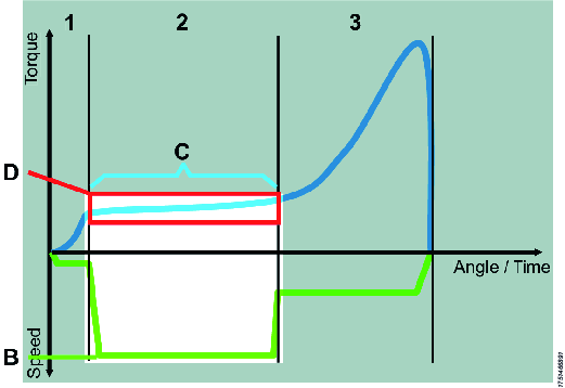 | B - High speed C - Transition to next step on angle, corresponding to the thread length before the screw head touches the work piece D - Torque window to supervise the run down and alert on faults, e.g. damaged thread It is important that the angle step stops before the screw head touches the work piece, if not it can lead to unwanted overshoots since the tool might not be able to break in time. |
Step 3: Clamping the joint
Use the torque step to clamp the joint.
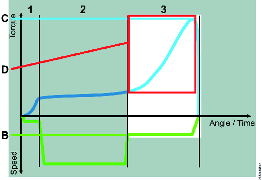 |
B - The speed the tool has been configured with C - The joint is finished when the target torque is reached D - Angle window from torque level to supervise the clamping and alert on faults, e.g. broken work piece or missing washer |
Add Pset with Quick programming on controller
It is possible to add a Pset or Verification program using the controller, see MTF 6000 Configuration guide.
Pset window
|
GUI object |
Description |
|
Change tool type |
Only available in offline mode. |
|
Test button |
Opens a window that enables you to start, stop and reset the active Pset |
|
Activate button |
Sets the current Pset to the active Pset on the controller. The Selected source must be set to Protocol/ToolsTalk MT. |
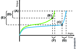
Key tightening definitions
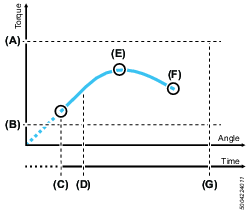
The screw is run down until the screw head touches the work piece at the seating point (A). The screw is then tightened until the final torque (C) is reached, this is often also the peak torque (B), but in some cases the final torque is lower.
The clamp angle (D) and clamp torque (E) is measured between the seating point and the peak torque.

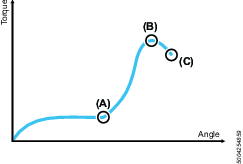
A | Seating point |
B | Peak torque |
C | Final torque |
D | Clamp angle |
E | Clamp torque |
General settings
Parameter | Description |
Pset name | Is shown in Pset list. The Pset name is stored with the result and will be displayed in the controller result view. |
Pset revision | Revision number of the Pset. |
Pset created | The date when the Pset was created. |
Pset modified | The date when the Pset was last modified. |
Configured tool name | The tool type the Pset was linked to (model type in text). |
Min. total time | Minimum time a tightening must run to pass as a tightening. |
Max. total time | Maximum time a tightening can run to pass as a tightening. |
Min. total angle | Minimum number of degrees the tool must turn during a tightening. |
Max. total angle | Maximum number of degrees the tool is allowed to turn during a tightening. |
Trigger lost torque | An error will be sent if the tool button is released after the Trigger lost torque value have been passed but before the tightening is completed. |
Graph start step | The number of the step from which the graph is started. |
Torque tuning | Adjust torque calibration for this Pset. The controller multiplies measured torque with the factor “(1.0 – Torque tuning)”. So a positive Torque tuning increases the applied torque. Torque tuning can be +/-0.1 |
Angle range start step | Defines from which step the result angle will start measuring. |
Angle range stop step | Defines from which step the result angle will stop measuring at. |
Min. angle range | Minimum number of degrees the tool must turn between angle range start and stop step. |
Max. angle range | Maximum number of degrees the tool is allowed to turn between angle range start and stop step. |
Requested Bit | Disables tool if requested bit is not picked from Accessory Bus bit selector. If no Accessory Bus bit selector is connected the tool will still be disabled. If set to None, parameter is not active. |
Final report step | Defines which tightening step in a Pset should report the final torque in the result. It is usually the last step in a Pset but can sometimes be another step. |
Final report torque | Decides if the final report step should report the peak, clamp or final torque. |
Final report angle | Decides if the final report step should report the step, clamp or tightening angle. |
Final seating point angle start step | Determines from what step the Final seating point angle result parameter should be calculated from. |
Bit slip detection | (Licenced feature) Bit slip is a function to detect when the bit slips out of the joint. It is a sign that the bit or the screw head is damaged. If bit slip occurs during a Seating Control Step or a Torque Seating Monitoring and bit slip is disabled, a seating can falsely be detected. |
Damaged thread detection | (Licenced feature) Will detect if the screw's threads have been damaged. |
Tool rehit | Pset defined rehit parameter that can override the global controller settings for rehit.
|
Configure Pset
The configuration pane includes the steps in the Pset.
Add step
There are two ways to add steps:
To add a single step, click the Add button.
To add several steps, right-click on the Add button and select the number of steps you want to add.
Delete step
To delete one or several steps, perform the following steps:
Mark the check box in front of the steps you want to delete.
Click the Delete button.
Click the Yes button in the Confirm window.
Thread engagement step
The thread engagement step is used to facilitate screw engagement, normally at low RPM (100-150 rpm). This step is finished by either reaching transition torque or transition angle. If the transition angle is set to infinite, the step can be finished only by reaching the transition torque or it will be aborted when the max. step time has been reached.
Parameter | Description |
Speed | The tool speed is programmable within the valid range. |
Transition torque (A) | The step is considered done when the step torque reaches the transition torque. |
Transition angel (B) | The step is considered done when the step angle reaches the transition angle. |
Direction | Direction of the tightening, clockwise or counterclockwise. Use clockwise setting for normal tightening. |
Vacuum enabled | Digital output to switch on an external vacuum pump. |
Fast speed change | Makes it possible to shift fast between fast and slow speed. When enabled it will be possible to get a more accurate torque estimation for current controlled tools over a longer time frame. This applies in the transition of the current step and the next step. |
Step start delay (E) | Delay from trigger to tool start. |
Min. step time (C) | Setting a minimum time for the step. If not reached the controller will display an error message. |
Max. step time (D) | Setting a maximum time for the step. If exceeded, the controller will display an error message. |
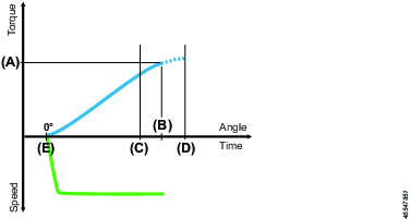
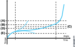
Angle step
The angle step is used to run the screw down for a certain number of revolutions, most of the time at high RPM. The angle step is finished when the angle target is reached.
A | Max. torque |
B | Min. torque |
C | Step start |
D | Min. step time |
E | Peak torque |
F | Target angle / Final torque |
G | Max. step time |
Parameter | Description |
Speed | The tool speed is programmable within the valid range. |
Target angle (F) | The angle that shall be reached to successfully complete the step. |
Direction | Use clockwise setting for normal tightening. |
Vacuum enabled | Digital output to switch on an external vacuum pump. |
Fast speed change | Makes it possible to shift fast between fast and slow speed. When enabled it will be possible to get a more accurate torque estimation for current controlled tools over a longer time frame. This applies in the transition of the current step and the next step. |
Min. torque (B) | The torque must not be below the set min. torque during the step. If the torque drops below the minimum torque the driver will stop and the controller will display an error message. If min. Torque is set above 0 cNm, add a step before the angle step to reach the set torque before the angle step starts. |
Max. torque (A) | The maximum torque value must not be exceeded during the step. If the maximum torque is reached, the driver will stop and the controller will display an error message. |
Step start delay | Delay from trigger to tool start. |
Min. step time (D) | Setting a minimum time for the step. If not reached the controller will display an error message. |
Max. step time (G) | Setting a maximum time for the step. If exceeded, the controller will display an error message. |
Torque step
The torque step is used for final tightening of the screw and to ensure that the correct torque is reached.

A | Max. torque |
B | Target torque |
C | Min. torque |
D | Rescinding torque limit |
E | Tightening angle trigger |
F | Tightening angle |
G | Min. angle |
H | Max. angle |
Parameter | Description |
Speed | The tool speed is programmable within the valid range. |
Target torque (B) | The target torque of the joint. This is also the final and peak torque of the step. |
Direction | Use clockwise setting for normal tightening. |
Vacuum enabled | Digital output to switch on an external vacuum pump. |
Min. torque (C) | If the minimum torque value is not reached, the controller will display an error message. |
Max. torque (A) | The maximum torque value must not be exceeded during this step. If the maximum torque is reached, the tool will stop and the controller will display an error message. |
Rescinding torque limit (D) | This monitor parameter sets a lower limit for the torque in this step. If the torque, at any time, drops below this limit the tightening will stop with an error message. |
Min. angle (G) | Angle that must have been reached when the step is finished. |
Max. angle (H) | Angle that must not be exceeded prior to reaching target torque. |
Step start delay | Delay from trigger to tool start. |
Min. step time | Minimum time for the step. If not reached, the controller will display an error message. |
Max. step time | Maximum time for the step. If exceeded, the controller will display an error message. |
Tightening angle trigger (E) | Once the tightening angle trigger value is reached, angle counting begins for this step. |
Min. tightening angle | The tightening angle must exceed the min. tightening angle for the tightening to pass. |
Max. tightening angle (G) | The maximum tightening angle (E) value must not be exceeded during this step. If the maximum tightening angle is reached, the tool will stop and the controller will display an error message. |
Torque seating monitoring step
This step is a torque step with additional seating monitoring. When a seating isn't found a tightening error will be triggered. It is also possible to collect clamp torque and clamp angle data. The torque seating monitoring step has a given target torque and includes a seating detection.
Parameter | Description |
Speed | The tool speed is programmable within the valid range. |
Target torque | The target torque of the joint. |
Seating angle displacement | Angle window for calculating the seating point from the gradient trigger point. |
Gradient trigger point | The torque level when the tool detects that the screw head has touched the work piece. This is the end point of the Seating angle displacement. |
Vacuum enabled | Digital output to switch on an external vacuum pump. |
Min. torque | If the total torque is below minimum torque, an error message will be displayed. |
Max. torque | The maximum torque value must not be exceeded during this step. If the maximum torque is reached, the driver will stop and the controller will display an error message. |
Rescinding torque limit | This monitor parameter sets a lower limit for the torque in this step. If the torque, at any time, drops below this limit, the tightening will stop with an error message. |
Min. angle | Angle that must have been reached when the step is finished. If not reached, the controller will display an error message. |
Max. angle | Angle that must be exceed when the step is finished. If exceeded, the controller will display an error message. |
Min. clamp torque | The min. clamp torque can be used to detect joint anomalies. |
Max. clamp torque | The max. clamp torque can be used to detect joint anomalies. |
Min. clamp angle | The min. clamp angle can be used to detect joint anomalies. |
Max. clamp angle | The max. clamp angle can be used to detect joint anomalies. |
Step start delay | Delay from trigger to tool start. |
Min. step time | Minimum time for the step. If not reached, the controller will display an error message. |
Max. step time | Maximum time for the step. If exceeded, the controller will display an error message. |
Seating control step
This step is specialized for joints with increased rundown friction, such as thread cutting, thread forming screws or joints with sideloads from misaligned parts.
In this type of applications it is common with variations from joint to joint. The main goal of this step is to eliminate floating screws and apply the same clamp torque or clamp angle to all joints even though the joints vary. The step monitors the gradient of the clamp torque over clamp angle and can detect when the screw is seated, that is when the screw head is in contact with the joint surface. From the seating point, the configured torque or angle is applied. The total torque or angle may differ from tightening to tightening but the same amount of clamp torque is used to compress the joint.
The method works as follows:
A torque level, the gradient trigger point, is set for detection of the point where the screw head is touching the work piece.
When the torque gradient exceeds the gradient trigger point, the seating point is detected. The torque gradient can be displayed in the tightening graph in the analysis window.
From this point, where the torque curve starts rising, the Seating point is calculated. This is done by calculating the mean torque from the gradient trigger point and looking back the amount of degrees from seating angle displacement.
This step type allows lower target torque and higher speeds than what the tool is calibrated for. This means that you may sometimes not get the desired results. If this happens, try to change the speed in order to get a more desired clamp value.

Parameter | Description |
Speed | The tool speed is programmable within the valid range. |
Final tightening method | Decides if the tightening should use clamp torque or clamp angle. |
Clamp torque (A) / Clamp angle (B) | Sets the value for the clamp torque or the clamp angle. |
Seating angle displacement (G) | Angle window for calculating the seating point from the gradient trigger point. |
Gradient trigger point (H) | The torque level when the tool detects that the screw head has touched the work piece. This is the end point of the Seating angle displacement. |
Vacuum enabled | Digital output to switch on an external vacuum pump. |
Min. torque (L) | If the total torque for a seating control step is below minimum torque, an error message will be displayed. |
Max. torque (D) | The Maximum torque value must not be exceeded during this step. If the Maximum torque is reached, the driver will stop and the controller will display an error message. |
Min. angle (F) | Angle that must have been reached when the step is finished. If not reached, the controller will display an error message. |
Max. angle (E) | Angle that must not be exceeded prior to reaching target torque. If exceeded, the controller will display an error message. |
Min. clamp torque | The min. clamp torque can be used to detect joint anomalies. |
Max. clamp torque | The max. clamp torque can be used to detect joint anomalies. |
Min. clamp angle | The min. clamp angle can be used to detect joint anomalies. If below, the controller will display an error message. |
Max. clamp angle | The max. clamp angle can be used to detect joint anomalies. If exceeded, the controller will display an error message and the tool will stop. |
Step start delay (M) | Delay from trigger to tool start. |
Min. step time (J) | Minimum time for the step. If not reached, the controller will display an error message. |
Max. step time (K) | Maximum time for the step. If exceeded, the controller will display an error message. |
Seating angle displacement (G) | Angle window for calculating the seating point from the gradient trigger point. |
Gradient trigger point (H) | The torque level when the tool detects that the screw head has touched the work piece. This is the end point of the Seating angle displacement. |
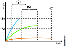
Friction Control Step
The friction control step is a smarter version of the angle step that can measure the average torque (friction) during the rundown phase. The step is finished when the target friction control angle is reached. The step will fail if the average torque is not within the average torque limits. Tightening will still be aborted if torque goes above/below the max/min torque limits.
A | Max. torque |
B | Max. average torque |
C | Average torque |
D | Min. average torque |
E | Min. torque |
Parameter | Description |
Speed | The tool speed is programmable within the valid range. |
Friction control angle | The angle that shall be reached to successfully complete the step. |
Direction | Direction of the tightening, clockwise or counterclockwise. Use clockwise setting for normal tightening. |
Vacuum enabled | Digital output to switch on an external vacuum pump. |
Fast speed change | Makes it possible to shift fast between fast and slow speed. When enabled it will be possible to get a more accurate torque estimation for current controlled tools over a longer time frame. This applies in the transition of the current step and the next step. |
Min. torque (E) | The torque must not be below the set minimum torque during the step. If the torque drops below the min. torque the driver will stop and the controller will display an error message. |
Max. torque (A) | The maximum torque value must not be exceeded during this step. If the maximum torque is reached, the tool will stop and the controller will display an error message. |
Min. average torque (D) | Minimum average torque value the step shall have at the end of the step. If min. average torque is not reached at the end of the step the tightening will be aborted with a NOK result. |
Max. average torque (B) | Maximum average torque value the step shall have at the end of the step. If max. average torque is exceeded at the end of the step the tightening will be aborted with a NOK result. |
Step start delay | Delay from trigger to tool start. |
Min. step time | Setting a minimum time for the step. If not reached the controller will display an error message. |
Max. step time | Setting a maximum time for the step. If exceeded, the controller will display an error message. |
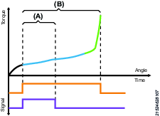
Digital Input Step
The digital input step will pause the ongoing tightening until a specific signal has been received by the controller.
This is not a hold step. Tool will pause the tightening and will not hold the torque.

A | Pause tightening and wait for signal |
B | Resume tightening |
C | Signal high |
D | Signal low |
Parameter | Description |
Input signal | External monitored 1-8 |
Signal flank |
|
Max. step time | Setting a maximum time for the step. If exceeded, the controller will display an error message. |
Vacuum enabled | Digital output to switch on an external vacuum pump. |
Digital Output Step
The digital output step will set a specific signal high/low. The signal can be set until a tightening or a specific duration have been completed.
A | Signal set HIGH for a specific duration |
B | Signal set HIGH until tightening is completed |
Parameter | Description |
Output signal | External monitored 1-10 |
Signal mode |
Output signal will always be reset at the end of the tightening, regardless of mode. |
Signal level |
|
Signal duration | Decides how long the output will be active. |
Smart Engagement Step
Smart engagement is used to facilitate screw engagement, normally at low RPM (100-150 rpm). Smart engagement first reaches an engagement torque and then has to stay below Max. torque and over the engagement torque during a set validation angle. By monitoring the torque during the validation angle and the tightening step angle, the step can instantly detect tilted and missing screws.
When reaching the set engagement torque a possible engagement is triggered. After reaching the engagement torque the controller will monitor the torque for a set validation angle to make sure that the screw is correctly engaged. If the tightening reaches max. torque or max. angle a retry action is triggered. A retry action can either consists of a retry or an abort. The user can define how the tightening should act according to the different errors. If the retry action is triggered due to max. torque it is most likely caused by a tilted screw and therefor retry is advised as a retry action.
If the retry action is triggered due to max. angle it is likely that the error was triggered by a missing screw and therefor abort is advised as a retry action.
Speed | The tool speed is programmable within the valid range. |
Engagement torque (A) | Activates validation angle after reaching the engagement torque. |
Validation angle (C) | Monitors the torque for a specified angle to make sure that the torque is above the engagement torque and below the max torque. Step is completed when these requirements are fulfilled. |
Retry action |
|
Loosening angle method |
|
Loosening angle | User defined angle used for retries. |
Loosening torque | Max. torque while loosening. |
Loosening speed | The speed set for loosening if a retry has been triggered. |
Direction | Direction of the tightening, clockwise or counterclockwise. Use clockwise setting for normal tightening |
Retry Signal | Defines what Externally Monitored Input should activate if the tool is currently loosening during a retry. |
Vacuum enabled | Digital output to switch on an external vacuum pump. |
Fast speed change | Makes it possible to shift fast between fast and slow speed. When enabled it will be possible to get a more accurate torque estimation for current controlled tools over a longer time frame. This applies in the transition of the current step and the next step. |
Max. torque (B) | If max torque is reached a retry action will be triggered. |
Max. angle (D) | If max angle is reached a retry action will be triggered. |
Retry limit | Number of times the tightening will try to retighten the screw after a retry action has been met. |
Step start delay | Delay from trigger to tool start. |
Min. step time | Minimum time for the step. If not reached, the controller will display an error message |
Max. step time | Maximum time for the step. If exceeded, the controller will display an error message. |
Smart Torque Seating Monitoring (Smart TSM)
The smart torque seating monitoring step is a smarter version of the torque step, with a brand-new seating detection algorithm. The smart TSM will tighten the screw to a desired target torque and will also monitor if the screw has found seating or not. If not, it will report a NOK Seating was not detected if the screw is floating. The controller needs to know an estimated clamp torque and clamp angle to calculate the seating detection. A detected seating point can be rejected if the torque gradient falls too low during the tightening. It will then be regarded as a false seating point and will continue to search for another seating point.
A | Target torque |
B | Seating point |
C | Seating point |
D | Clamp torque |
E | Clamp torque |
F | Clamp angle |
G | Clamp angle |
Speed | The tool speed is programmable within the valid range. |
Target torque | The target torque of the joint. |
Clamp torque | Expected clamp torque for the tightening. |
Clamp angle | Expected clamp angle for the tightening. |
Vacuum enabled | Digital output to switch on an external vacuum pump. |
Min. torque | If the minimum torque has not been reached when the step is finished, an error message will be displayed. |
Max. torque | If the maximum torque is reached before the step is finished, the tool will stop and the controller will display an error message. |
Rescinding torque limit | This monitor parameter sets a lower limit for the torque in this step. If the torque, at any time, drops below this limit, the tightening will stop with an error message. Setting this parameter to 0 will disable the rescinding torque monitoring. |
Min. angle | If the minimum angle has not been reached when the step is finished, an error message will be displayed. |
Max. angle | If the maximum angle is reached before the step is finished, the tool will stop and controller will display an error message. |
Min. clamp torque | The minimum clamp torque can be used to detect joint anomalies. If below, the controller will display an error message. |
Max. clamp torque | The maximum clamp torque can be used to detect joint anomalies. If exceeded, the tool will stop and the controller will display an error message. |
Min. clamp angle | The minimum clamp angle can be used to detect joint anomalies. If below, the controller will display an error message. |
Max. clamp angle | The maximum clamp angle can be used to detect joint anomalies. If exceeded, the tool will stop and the controller will display an error message. |
Step start delay | Delay from trigger to tool start. |
Min. step time | Minimum time for the step. If not reached, the controller will display an error message. |
Max. step time | Maximum time for the step. If exceeded, the controller will display an error message. |
Smart Seating Control Step (Smart SCS)
This step is specialized for joints with increased rundown friction, such as thread cutting, thread forming screws or joints with sideloads from misaligned parts. In these types of applications, it is common with variations from joint to joint. The main goal of this step is to eliminate floating screws and apply the same clamp torque or clamp angle to all joints even though the joints deviate. The step monitors the gradient of the clamp torque over clamp angle and can detect when the screw is seated, that is when the screw head is in contact with the joint surface. From the seating point, the configured clamp torque or clamp angle is applied. The total torque or angle may differ from tightening to tightening but the same amount of clamp torque, or clamp angle, is used to compress the joint. The clamp torque and clamp angle are set to tell the controller what it should expect after detecting a seating. (The seating detection is calculated based on these values.) A detected seating point can be rejected if the torque gradient falls too low during the tightening. It will then be regarded as a false seating point and will continue to search for another seating point.
This step type allows lower target torque and higher speeds than what the tool is calibrated for. This means that you may sometimes not get the desired results. If this happens, try to change the speed in order to get a more desired clamp value.

A | Peak torque |
B | Peak torque |
C | Seating point |
D | Seating point |
E | Clamp torque |
F | Clamp torque |
G | Clamp angle |
H | Clamp angle |
Speed | The tool speed is programmable within the valid range. |
Final tightening method | Decides if the tightening should use clamp torque or clamp angle as target. |
Clamp torque | Expected clamp torque for the tightening. |
Clamp angle | Expected clamp angle for the tightening. |
Vacuum enabled | Digital output to switch on an external vacuum pump. |
Min. torque | If the minimum torque has not been reached when the step is finished, an error message will be displayed. |
Max. torque | If the maximum torque is reached before the step is finished, the tool will stop and the controller will display an error message. |
Min. angle | If the minimum angle has not been reached when the step is finished, an error message will be displayed. |
Max. angle | If the maximum angle is reached before the step is finished, the tool will stop and controller will display an error message. |
Min. clamp torque | The minimum clamp torque can be used to detect joint anomalies. If below, the controller will display an error message. |
Max. clamp torque | The maximum clamp torque can be used to detect joint anomalies. If exceeded, the tool will stop and the controller will display an error message. |
Min. clamp angle | The minimum clamp angle can be used to detect joint anomalies. If below, the controller will display an error message. |
Max. clamp angle | The maximum clamp angle can be used to detect joint anomalies. If exceeded, the tool will stop and the controller will display an error message. |
Step start delay | Delay from trigger to tool start. |
Min. step time | Minimum time for the step. If not reached, the controller will display an error message. |
Max. step time | Maximum time for the step. If exceeded, the controller will display an error message. |
Loosening
The loosening step is used to loosen or unscrew a screw.
Parameter | Description |
Loosening torque | Maximum torque allowed for a loosening. |
Loosening angle | Maximum angle allowed for a loosening. |
Loosening speed | Speed for loosening. |
Loosening max time | Maximum time for a loosening. If exceeded, the controller will display an error message. |
Loosening vacuum pump | Digital output to switch on an external vacuum pump. |
Loosening start delay | Delay from trigger to tool start. |
Force loosening on NOK | Forces the user to conduct a loosening before another tightening can be done. This feature is disabled when run from a Batch Sequence. |
Screw pickup
Screw pickup helps the operator to pick up a screw before starting the tightening. The first start signal will trigger the screw pickup function and the second start signal will trigger the tightening. Meaning that the start signal must be pressed/triggered twice to activate the tightening procedure.
Tightening procedure when Screw pickup is enabled:
Activate start signal to pick up screw.
Place the screw in the correct position.
Activate the start signal again to trigger the tightening.
Parameter | Description |
|---|---|
Not aligned limit | Vacuum level required to acknowledge that a screw has been picked up. |
Aligned limit | Vacuum level required to acknowledge that the screw is aligned. |
Screw pickup | Indicates if the function is enabled. |
Screw pickup can be used both for handheld and automatic operations. The parameters Not aligned limit and Aligned limit requires the use of Vacuum Pump MT, which is only compatible with a controller with MTF6000 revision C or later.
If screw pickup is enabled, the following parameters can be configured:
Parameter | Description |
|---|---|
Vacuum pump | Starts vacuum pump upon activating screw pickup function |
Rotate bit on pickup | Bit rotates slowly CCW to help attach the bit to the screw. |
Timeout | Timeout is used to set an interval how long the pickup should take. If the time is exceeded the controller will leave the busy state and go back to idle. |
Guiding light | Activates the MT tool guiding light upon activating screw pickup function. |
Pickup guide
Vacuum pickup guide is available with Vacuum pump MT (8432 0854 00) and a controller with MTF6000 revision C or later. Click PICKUP GUIDE to open the wizard. The vacuum starts automatically if the vacuum pump MT is connected.
On the wizard page, you can set the limits by moving the limit indicators up and down. A two-step setup guide is also available by clicking SETUP GUIDE:
Follow the instructions on the screen to set the value when the screw is picked up but not aligned.
Follow the instructions on the screen to set the value when the screw is picked up and aligned.
You can always manually update the values afterwards.
Custom View
The custom view makes it possible to customize the last view on the controller. The selected information will only be displayed during the selected Pset. If no Pset is selected the screen will be blank.
The screen can be configured to show one to four fields. For each field it is possible to display general or step information.
The first field have a white background, the following have grey background. This is to give a focal point and have no other intended meaning.
General data
Parameter | Description |
|---|---|
Final torque | Shows the final torque of the tightening. Final torque can be configured in the general settings of the Pset. |
Peak torque | Shows the maximum achieved torque in the tightening. |
Tracking torque | Follows the torque during the tightening. |
Final angle | Shows the final angle of the tightening. Final angle can be configured in the general settings of the Pset. |
Total angle | Shows the total angle of the tightening. |
Tracking angle | Follows the angle during the tightening. |
Tightening error | Shows the current error message, blank if no current error. |
Pset name and number | Shows Pset number and name. |
Controller date | Controller date. |
Controller name | Controller name (configured under Controller settings). |
Station name | Station name (configured under Controller settings). |
Line name | Line name (configured under Controller settings). |
Logged in user | Displays if any user level is logged in (L1-L3) or "-" if no user is logged in. |
Tightening duration | The time in seconds of the last tightening. |
Tool serial number | The serial number of the connected tool. |
Tool type | The type of the connected tool. |
Calibration date | Date of last calibration. |
Tool statistics | Tool statistics, displays the OK and NOK tightenings since last calibration. |
Select source | Displays the source of Pset and batch sequence selections. |
Controller time | Controller time. |
Tool temp | Current temperature of tool. |
Vacuum pressure | Displays real time vacuum pressure in kPa. |
Step data
Parameter | Description |
|---|---|
Step number | Selects from which step the parameter "Step data" shall get its values from. |
Step peak torque | Shows the maximum achieved torque in the selected step. |
Step clamp torque | Shows the achieved clamp torque in the selected step. |
Step transition torque | Shows the maximum last measured torque in the selected step. |
Step angle | Shows the achieved angle for the selected step. |
Step clamp angle | Shows the achieved clamp angle in the selected step. |
Seating point | Shows the seating torque of the step. |
Tightening angle | Shows the tightening angle for the selected step |
Verification Program
The Verification program is a specific form of Psets that can be used to verify the tool accuracy together with an IAM QA controller.
A Verification program is a form of torque step with limited parameter input. The window limits will not be set on the tightening itself but can be sent to the IAM QA controller to set limits on the measured torque.
General data
Parameter | Description |
Name | Is shown in Verification program list. The Verification program name is stored with the result and will be displayed in the controller result view. |
Revision | Revision number of the Verification program. |
Created | The date when the Verification program was created. |
Modified | The date when the Verification program was last modified. |
Configured tool name | The tool type the Verification program was linked to (model type in text). |
Control limit | How much the reference value can deviate from:
|
Verification size | Number of tightenings to perform for the testing of the tool |
Verification mode | Decides what the verification result should trigger on.
|
Measurement Evaluation mode | The measurement will compare the Target or Tool peak value against the QA reference and the control limit to see if a measurement should be OK or NOK. Current controlled tools are locked to Target vs Reference. (read only parameter) Transducerised tools are editable and has the possibility to select between:
|
Minimum CMK | Minimum allowed CMK value (disable chef if set to 0). |
On Verification complete | Decides what shall happen after the verification program is completed.
|
Operator ID required |
|
Step data
Parameter | Description |
|---|---|
Speed | The speed to tool will run at during the test. |
Target torque | The target torque the test shall be performed on. |
Vacuum enabled | If enabled, the vacuum is activated during the test. |
Step start delay | Set a start delay of the tightening |
Batch sequence

This function provides the possibility to control a sequence of screw joints with different tightening strategies related to the assembly of one workpiece.
Batch
To set-up a batch a pre-defined Pset and a batch size is needed, that is the number of tightenings to be performed.
It is possible to define a repair Pset and a repair limit. If a tightening fails, the repair limit is incremented. If the repair attempts exceed the repair counter the whole batch sequence is failed.
It is possible to set two timeout values, from start and from tightening. If a batch takes longer time than the set value, the batch is failed and aborted.
Event
The event step can be used to interact with the workstation and control the flow of the tightening process.
Input
The input step will wait for the Batch Sequence DI1-12 signal to be in a desired state, set by the Signal flank parameter. Signal flank defines if the input step should react on changes from low to high (positive flank), high to low (negative flank), just being high/low or react to any signal changes (any).
Output
The output step will set a Batch Sequence DO1-8 signal in a desired state, set by the Output signal level parameter.
Output signal level defines if the signal should be set high (one) or low (zero). The output mode defines if the signal should be permanently set to the output signal level or be pulsed (duration). In the case of duration, the time for the pulse must be selected. The max time for the pulse is three seconds, if a longer step is needed it is possible to use two output steps in set mode with a delay step in-between.
Delay
It is possible to delay the sequence for a given time between 0.01 and 30 seconds.
Advanced scan
This step forces the user to scan a barcode or read a RFID-tag. The data can be stored with the tightening result data for traceability.
Configuring this step requires one or more pre-defined identifiers. An identifier is a rule that is used to verify if the scanned string is correct.
This step can house up to four identifiers, this is to manage variations in product serial numbers. For example it can be that the scan will store the serial number of a module in the product. The module can come from two different suppliers and have different serial numbers. Then serial numbers of both types should be accepted as correct.
Simple scan
This step forces the user to scan a barcode or read a RFID-tag. The data can be stored with the tightening result data for traceability.
The information is saved to a custom ID. No validation is made.
Input monitor step
The input monitor step can be used to monitor the level of a digital input during the batch sequence. When triggered, the batch sequence will be aborted and the sequence is restarted.
Bit selector
The bit selector step can be used to force the operator to change bit before continuing.
Introduction to the batch sequence list
Each line represents one batch sequence. The columns contain the following information:
Check box to select the batch sequence
Number
Name, a user defined name
Number of
Active
Last change
It is possible to sort the list by clicking the header of each column.
Adding a batch sequence
To add a batch sequence, perform the following steps:
-
Click the Batch sequence icon in the Menu bar. The workspace area shows a list of all the current batch sequences.
-
Click the Add button. The Create batch sequence window opens.
-
Enter batch sequence number and name.
-
Click the OK button.
A new batch sequence is added at the place of select number and the list is updated.
Deleting a batch sequence
To delete a batch sequence, perform the following step:
-
For each batch sequence to be deleted, mark the check box in the left most column in the workspace area.
-
Click the DELETE button.
-
Confirm the deletion in The Confirm window.
The selected batch sequence(s) are removed and the list is updated.
Copy batch sequence
To copy a batch sequence, perform the following steps:
-
Right-click on the batch sequence you want to copy.
-
Select Copy.
-
Right-click on the batch sequence you want to copy to.
-
Select Paste.
-
To confirm, press the Yes button in the Confirm window.
General settings
Parameter | Description |
Batch sequence name | Is shown in the batch sequence list. Will be displayed on the result screen on the controller. Will be saved together with all tightening results made in the batch sequence. |
Batch sequence revision | Revision of the batch sequence. |
Batch sequence created | The date when the batch sequence was created. |
Batch sequence modified | The date when the batch sequence was last modified. |
Beep on error | When enabled, the controller will beep if a batch sequence has failed. |
Abort time | If a batch sequence takes longer time than this, the batch sequence is failed and aborted with an error message. |
Reset idetifier on batch sequence complete | When enabled, the controller will clear the contents of Custom ID 1-4 upon the completion of a batch sequence. |
Configuration
The configuration pane includes the batch, events or information steps in the batch sequence.
Add batch, event or information step
There are two ways to add steps:
-
To add a single step, click the Add button.
-
To add several steps, right-click on the Add button and select the number of steps you want to add.
-
Click the Add button.
Delete batch, event or information step
To delete a batch, event or information step perform the following steps:
-
Mark the check box in front of the batch, event or information step you want to delete.
-
Click the Delete button.
-
Click the Yes button in the Confirm window.
Batch parameters
A batch is a series of tightenings with one defined Pset.
Parameter | Description |
Pset number | Number of the Pset to use. |
Batch size | The number of tightenings with the selected Pset. |
Repair mode | Enabled/Disabled. If enabled the loosening trigger will automatically be disabled until a tightening error. When the loosening trigger is enabled the tool trigger is disabled. After a loosening, the repair Pset mode is enabled. |
Increment batch counter on | OK or OK/NOK. Should the batch counter increase on OK tightenings only or on OK and Not OK tightenings. |
Fail on NOK no. | The maximum number of allowed failed tightenings during a batch. |
Repair Pset | Select a repair Pset. |
Repair limit | If a tightening fails, the repair limit is incremented. If the repair attempts exceed the repair counter the whole batch sequence is failed. |
From start | The maximum execution time for the batch step. If the batch step takes longer time than this, the batch sequence is failed and aborted with an error message. |
From tightening | The maximum execution time for a batch step counting from the start of the first tightening. If the batch step takes longer time than this, the batch sequence is failed and aborted with an error message. |
Event parameters
Parameter | Description |
Event type | Advanced scan, input, output, delay, simple scan, input monitor or bit selector. |
Advanced scan
Parameter | Description |
Identifier source | Protocol, scanner, any |
Identifier rule 1-4 | Up to four identifier rules to parse incoming identification strings. |
Information text | User defined text to be displayed on the screen during the advanced scan step. |
Timeout | If an Advanced scan takes longer time than this, the batch sequence is failed or aborted. |
Input
Parameter | Description |
Input signal | Decides which Batch Sequence DI1-12 signal to wait for. |
Signal flank | Decides if the step should react to positive/negative/any flank or positive/negative level. |
Timeout | If an Input step takes longer time than this, the batch sequence is failed or aborted. |
Information text | User defined text to be displayed on the screen during the step. |
Output
Parameter | Description |
Output signal | Decides which Batch Sequence DO1-8 to set. |
Output signal mode | Decides if the signal should be permanently set or for a set time. |
Output signal level | Decides if the output should be set high or low. |
Output signal duration | Appears if signal mode is set to duration and decides for how long the output should be active. |
Delay
Parameter | Description |
Delay time | Decides for how long the event will stay active. Can be set from 0.01-30 s. |
Simple scan
Parameter | Description |
Identifier source | Protocol, scanner, any |
Save destination | Save to one Custom ID. |
Information text | User defined text to be displayed on the screen during the simple scan step. |
Timeout | If a simple scan takes longer time than this, the batch sequence is failed and aborted with an error message. |
Key | Static text defined by user and saved with data in custom ID. |
Input monitor
The input monitor step can be used to monitor the level of a digital input during the batch sequence. When enabling an input monitor it will be active until end of the batch sequence or until it is disabled.
If the monitor error is triggered, it will activate a batch sequence error and the sequence will be aborted.
Parameter | Description |
Monitor mode | Enable or disables the input monitor. If enabled the input monitor will be active until the end of the batch sequence or until disabled. |
Input signal | Select the batch sequence input signal that should be monitored. The input signal must be assigned to an actual input in the I/O configuration. |
Trigger error on | If the signal assumed the error trigger state, high or low, the batch sequence will be aborted and a batch sequence error will be active. |
Bit selector
The bit selector step will force the user to pick up a specific bit in order to complete the step.
Digital I/O bit selector
Digital input function "Select bit 0-3" must be linked in order to detect if a bit is selected. The bit selector event will always set digital output function "Unlock bit 0-3" to identify which bit that should be selected to an external device.
"Unlock bit" and "Select bit" are both calculated binary.
Select Bit 0 weight = 1
Select Bit 1 weight = 2
Select Bit 2 weight = 4
Select Bit 3 weight = 8
Example: If Event is set to take Bit #7 then Select Bit 0, 1 and 2 should be high in order to complete the event step. (1 + 2 + 4 = 7)
Accessory Bus bit selector
The Accessory Bus uses its own protocol and has nothing to do with the digital I/Os. There is no need to link any "Select bit" to make the accessory bus bit selector work.
Example: If event is set to take Bit#7 then the selector indicator LEDs will show which bit to pick, which is the bit located at position number 7.
Parameter | Description |
Requested Bit | Select which bit the operator shall pick in order to continue on with the step. It is possible to select up to 8 different bits. (These bits are independent of the settings in configuration and will not execute any other command if picked.) |
Identifier source | Select from which source the signal shall come from Digital I/O or Accessory Bus. |
Information parameters
|
Parameter |
Description |
|
Information text |
User defined text to be displayed on screen during the information step. |
|
Information transition mode |
This parameter defines how the information step is finished. It can transition to the next step after a given time or after a press of the OK button. |
|
Information transition time |
If transition mode is selected, a time can be entered. |
|
Buzzer frequency |
The frequency of the buzzer. |
|
Buzzer duration |
The duration of the buzzer - set to zero if no buffer wanted. |
Identifiers

Identifiers are used to both store valuable information, such as operator ID and serial numbers in each result and also to select the next task for the controller.
Identification strings can be inserted into the controller either via Open protocol, Fieldbus or a Scanner.
The inserted/scanned value is validated according to the predefined identifiers and if the controller finds a match it will perform the action of that identifier.
There are several different ways of using inserted/scanned data:
Traceability and production monitoring (Operator ID, Store in Custom ID and Save ID)
Work control (Select Pset, Verification program and Batch sequence)
User access control (Login).
To configure how inserted/scanned values are used, the user needs to setup identifier rules. These rules first tries to validate an incoming identification string (scanner input). If the identification string is validated by the rule, it will issue an action to the system.
Scanner
A scanner can be connected to a USB or a serial port on the controller.
The USB-scanners must have:
USB HID interface (Keyboard)
English-US keyboard interface
MTF6000 offers the possibility of connecting scanners via USB HID (as keyboard) and RS232. It is possible to use any type of scanner that uses any of these interfaces. The system will accept text strings of up to 512 characters.
Creating station barcode
For traceability between the tightening and measuring controller it is possible to generate a station barcode containing information regarding tool, torque, controller ID, and so on. This station barcode is automatically generated inside the MTF6000 if a verification program is selected and shown on the controller display. If the controller is out of range for the quality operator it is possible to manually generate a station barcode in ToolsTalk MT that can be printed and placed next to the station so the barcode can be scanned by the IAM QA controller. The values in the station barcode is stored together with the measurement result to gain traceability between the tightening and measurement result.
In the identifier list view, click Barcode to create a station barcode. Since the station barcode is entered manually in ToolsTalk MT, it is possible to enter any values, which means that the tightening can be made with a non MTF6000 controller and the IAM QA controller will store the information regardless.
Adding an identifier
To add a identifier perform the following steps:
-
Click the Identifier icon in the Menu bar. The workspace area shows a list of all the current identifiers.
-
Click the Add button. The Create window opens.
-
Enter identifier number and name.
-
Click the OK button.
A new identifier is added at the place of select number and the list is updated.
Deleting an identifier
To delete a identifier, perform the following step:
-
For each identifier to be deleted, mark the check box in the left most column in the workspace area.
-
Click the DELETE button.
-
Confirm the deletion in The Confirm window.
The selected identifier(s) are removed and the list is updated.
Copy identifier
To copy an identifier, perform the following steps:
-
Right-click on the identifier you want to copy.
-
Select Copy.
-
Right-click on the identifier you want to copy to.
-
Select Paste.
-
To confirm, press the Yes button in the Confirm window.
General settings
|
Parameter |
Description |
|
Name |
Name of the identifier. |
|
Identification string |
The set string. The Enter/Scan button can be used to manually enter a barcode. |
Validation
The validation settings are used to verify if the rule applies to the incoming identification string. If the rule applies, the controller will execute the actions attached to the rule.
It is possible to select anything from 1 to 64 characters in the string to match against a given text.
Example:
Match part-> 1-3, 9-10
Match string->SNPDL
String 1-> SNP12345DL -> Match (bit 1-3 is SNP and bit 9-10 is DL)
String 2-> SNPDL1234 -> No match (bit 1-3 SNP but bit 9-10 is 34)
For firmware version 1.15.0 and later it is possible to add an Accept anything validation. Set the Length to 0 and leave the Match Part and Match Text empty. Do not create more than one accept anything validation on the same controller.
Parameter | Description |
Identification string length | Length of identification string. Set automatically when the Enter/scan button and then the OK button is clicked. |
Match part | Positions in the indentification string. The selection is done in a separate window. |
Match string | Characters that will match the string according to the match part. |
Configuration
In all identifier actions except login it is possible to save up to 100 characters in each custom ID. This string will then be attached to the result data from the tightening.
There are four custom ID slots that the user can fill with text. Each custom ID has two fields, key and format. The key value is a static text that can be entered when configuring the identifier. The value field will be filled when the scan happens. The value format setting decides what data is entered into the field, it will define the number and order of bits to select.
Parameter | Description |
Action type | Save ID
Select VProg |
Keep until replaced |
|
Save ID
The Save ID action can only be used inside a batch sequence.
This action is used to save data from the scanned tag with the result data. By adding a static key the data will be searchable in a database. It is possible to set up to four save strings. The scanner input can save 100 key characters and 100 scanned characters, that is, 200 in total.
Parameter | Description |
Key 1-4 | Static text defined by user saved with scanner data. |
Format 1-4 | The part of incoming string that will be saved in the custom ID. |
Save destination 1-4 | None |
Select Pset
This action can only be executed if the selected source is set to scanner. This is set in Controller settings > Configuration > Select source.
This action will select a Pset.
Parameter | Description |
Pset | Select from available Psets. |
Key 1-4 | Static text defined by user saved with scanner data. |
Format 1-4 | The part of incoming string that will be saved in the custom ID. |
Save destination 1-4 | None |
Select batch sequence
This action can only be executed if the selected source is set to scanner. This is set in Controller settings > Configuration > Select source.
This action will select a batch sequence.
Parameter | Description |
Batch sequence | Select from available batch sequences. |
Batch sequence restart mode | Decide whether the batch sequence should wait for a new scan or start automatically when it finishes. |
Key 1-4 | Static text defined by user saved with scanner data. |
Format 1-4 | The part of incoming string that will be saved in the custom ID. |
Save destination 1-4 | None |
Store in custom ID
Store in custom ID can be used to save a scanned value without any dependencies to other functions.
Parameter | Description |
Key 1-4 | Static text defined by user saved with scanner data. |
Format 1-4 | The part of incoming string that will be saved in the custom ID. |
Save destination 1-4 | None |
Operator ID
Stored in the QA controller to link an operator with a measurement result.
Parameter | Description |
|---|---|
Operator ID format | The part of incoming string that will be saved as the Operator ID. |
Open IDENTIFIERS.
Press ADD.
Open identifier.
Setup validation.
Setup operator ID format.
Go back to IDENTIFIERS.
Press OPERATORS.
Press ADD.
Enter Key (value that must match the format that was setup under operator id format).
Enter Name (Name of operator).
Example
Setup identifier
Parameter
Value
Identification string length
6
Match part
{1-3}
Match string
ABC
Operator ID format
{4-6}
Setup operators
Operator
Parameter
Value
1
Key
001
Name
Atlas
2
Key
002
Name
Copco
Result
Barcode
Operator
ABC001
Atlas
ABC002
Copco
ABC003
N/A
ABC0010
N/A
Select Vprog
This action can only be executed if the selected source is set to scanner. This is set in Controller settings > Configuration > Select source.
This action will select a Verification program.
Parameter | Description |
VProg reference | Select from available Psets. |
Vprog restart mode | Decide whether the verification program should wait for a new scan or start automatically when it finishes. |
Key 1-4 | Static text defined by user saved with scanner data. |
Format 1-4 | The part of incoming string that will be saved in the custom ID. |
Save destination 1-4 | None |
Login
This action enables a user to log in to a user level. The user level is set in I/O and Password settings > Password > Controller.
Scanning the code while logged in will automatically log out the user.
|
Parameter |
Description |
|
Level |
Select level 1 to 3. |
Station barcode
The station barcode can be manually entered to create a QR code containing information about the tool and controller which can be sent to the IAM QA controller via a scanner.
Parameter | Description |
|---|---|
Tool serial number | Serial number of the tightening tool. |
Controller serial | Serial number of the tightening controller. |
Controller ID | Controller ID of the tightening controller. |
Station ID | Station ID of the tightening controller. |
Line ID | Line ID of the tightening controller. |
Verification program instance no | Tightening program number. |
Tool type | Type of tool that will perform the tightening. |
Calibration date | Date of tool calibration. Expressed in YYYY-MM-DD. |
Target torque | The amount of torque the controller will tighten to and the measurement target. |
Control limit | Max allowed deviation from target/tool and used to calculate the CMK. |
Verification size | Number of tightenings to perform for the testing of the tool. |
Minimum CMK | Minimum value CMK can have to report a verification OK (if CMK is below min value the verification will report NOK). If parameter is empty or set to 0 then the verification will evaluate the result according to the measurement results. |
Operator ID required |
|
Save
Saves the QR code and all parameters as a picture in .jpg or .bmp format on your computer.
Export
Saves the parameters in an .xml file on your computer which can be imported and re-edited at a later time.
Import
Imports an existing .xml file containing all the parameters and their values.
Print
Prints the QR code and all parameters in a nice format that is ready to be placed next to the tightening station.
Load parameters
Load active controller parameters into the appropriate fields. Parameters that will be loaded into the station barcode are:
Tool serial number
Controller serial number
Controller ID
Station ID
Line ID
Tool type
Configurations

This function provides the possibility to control the bit selector behavior, stacklight behavior, the transducers and the tool functions, such as buttons and LED lights.
Configurations list
Each line represents the configurations for a specific tool/transducer family or accessory. The columns contain the following information:
Check box to select configuration
Name, a user defined name
Last change
Configuration type
ETD M
ETD M + PTS (push to start)
ETD MC/MT
ETD MC/MT + PTS (push to start)
QMC/QMT
MT TS/TH/TRA
Bit Selector
Stacklight
Active
Adding a configuration
When connecting a tool or a transducer with the controller, the controller will automatically add a configuration for that tool family or transducer type.
Select Add to open the Configuration window.
Enter Name and select a tool family or transducer type, then select OK.
A new Configuration is added and the list is updated.
Select Add to open the Configuration window.
Select the accessory in the list.
Deleting a configuration
To delete one or several configurations:
Select the check box of the configurations that you want to delete and then click Delete.

Active Configurations cannot be deleted.
Click Confirm in the dialogue box.
The configurations are removed and the list is updated.
General settings
Parameter | Description |
|---|---|
Name | User defined name which is shown in the configurations list. |
Configuration revision | Revision of the configuration. |
Created | Creation date of the configuration. |
Modified | Latest modification date of the configuration. |
Configurations
The configuration options vary depending on transducer or tool types. For tools, the tool trigger, lights and tactile feedback can be configured.
The controller will automatically create a configuration if a new tool/transducer type is connected to the controller.
It is not possible to create several configurations for the same tool/transducer type.
Parameter | Description |
|---|---|
Configuration type | Tool/Transducer configuration |
Tool family | Name of current tool family (only valid for tool configuration) |
ETD M / ETD M + PTS
Parameter | Description |
|---|---|
Tool start trigger |
|
Tool loosening trigger |
|
Trigger Push-To-Start |
|
ETD MC/MT / ETD MC/MT + PTS
Parameter | Description |
|---|---|
Tool start trigger |
|
Trigger start function | Only available if Tool start trigger is set to Disabled.
|
Trigger start input function | Only available if Tool start function is set to Input function. See also Digital I/O |
Trigger Push-To-Start |
|
Config single function |
|
Config single input function | Only available if Config single function is set to Input function. See also Digital I/O |
Config single output function | Only available if Config single function is set to Toggle output function or Pulse output function. |
Config double function |
|
Config double input function | Only available if Config double function is set to Input function. See also Digital I/O |
Config double output function | Only available if Config double function is set to Toggle output function or Pulse output function. |
Config hold function | Configurations will take effect approximately one second after pressing the button.
|
Config hold input function | Only available if Config hold function is set to Input function. See also Digital I/O |
Config hold output function | Only available if Config hold function is set to Toggle output function or Pulse output function. |
Led intensity | Sets the brightness for the LED of green, blue and red. Scale is from 1-5. |
Led timeout | Sets for how many seconds the LED will be on after activating green, blue or red. Timeout can be set to 0-300 where 0 is infinity. |
Led OK |
|
Led NOK |
|
Led batch OK |
|
Led batch OK color | Only available if Led batch OK is set to enabled.
|
Led guiding intensity | Sets the brightness for the LED of guiding light. Scale is from 1-5. |
Led guiding timeout | Sets for how many seconds the LED will be on after activating guiding light. Timeout can be set to 0-300 where 0 is infinity. |
Tactile on NOK |
|
QMC / QMT
Parameter | Description |
|---|---|
Led intensity | Sets the brightness for the LED of green, blue and red. Scale is from 1-5. |
Led timeout | Sets for how many seconds the LED will be on after activating green, blue or red. Timeout can be set to 0-300 where 0 is infinity. |
Led busy |
|
Led OK |
|
Led NOK |
|
Led batch OK |
|
Led batch OK color | Only available if Led batch OK is set to enabled.
|
Transducer
Parameter | Description |
|---|---|
Type | Type of transducer. For example, MT-TS |
Name | Transducer name. |
Max torque | Highest torque the transducer can measure. |
Torque threshold | Start/Stops measurement after reaching threshold. |
Torque target | What the measurement aims to reach. |
Control limit | How much the measurement in % can deviate from the target/tool torque. Is also used to calculate the CMK. |
Verification size | Number of measurements in the test. |
Verification mode |
|
Minimum CMK | Minimum allowed CMK to report a verification OK. If final CMK is below this value then the verification will report a NOK. |
Bit Selector
If using the Digital I/O Bit selector the Select source must be set to Digital I/O and I/O Select mode must be set to Bit selector. If using the Accessory Bus Bit Selector the Select source must be set to Accessory Bus Protocol.
Parameter | Description |
|---|---|
Sensor [1-8] | Only available in Accessory Bus bit selector
|
Bit [1-8] Select mode | If Sensor [1-8] is set to Disabled, None will be the only available option.
|
Bit [1-8] Pset | Select which Pset to activate if Bit is selected. Only available if Bit [1-8] select mode is set to Select Pset. |
Bit [1-8] Batch Sequence | Select which Batch sequence to activate if Bit is selected. Only available if Bit [1-8] select mode is set to Select Batch sequence. |
Stacklight
Parameter | Description |
|---|---|
Stacklight [1-5] function | Select which output function to connect to the corresponding stacklight light. |
Stacklight [1-5] signal mode | Select the mode of the signal. Not available if Stacklight [1-5] function is set to Disabled. The options are the same as for the Digital I/O Output signal mode.
|
Stacklight [1-5] signal duration | Only available if Stacklight [1-5] signal mode is set to Duration. |
Stacklight [1-5] flashing | Not available if Stacklight [1-5] function is set to Disabled.
|
Buzzer function | Select which output function to connect to the Buzzer. |
Buzzer signal mode | Select the mode of the signal. Not available if Buzzer function is set to Disabled. The options are the same as for the Digital I/O Output signal mode.
|
Buzzer signal duration | Only available if Buzzer signal mode is set to Duration. |
Component [A,B] |
|
Component [A,B] function | Select which input function is connected to corresponding Component [A,B]. Only available if Component [A,B] is set to One-way switch, Push button or Color button. |
Component [A,B] left function | Select which input function is connected to corresponding Component [A,B]. Only available if Component [A,B] is set to Two-way switch. |
Component [A,B] right function | Select which input function is connected to corresponding Component [A,B]. Only available if Component [A,B] is set to Two-way switch. |
Component [A,B] lamp function | Select which input function is connected to corresponding Component [A,B]. Only available if Component [A,B] is set to Color button or Lamp. |
Component [A,B] lamp signal mode | Select the mode of the signal. Only available if Component [A,B] is set to Color button or Lamp. |
Component [A,B] lamp signal duration | Only available if Component [A,B] lamp signal mode is set to Duration. |
Component [A,B] lamp flashing | Not available if Component [A,B] function is set to Disabled.
|
Output [1-2] function | Select which output function to connect to the corresponding Output [1-2] function. |
Output [1-2] signal mode | Select the mode of the signal. Not available if Output [1-2] function is set to Disabled. The options are the same as for the Digital I/O Output signal mode.
|
Output [1-2] signal duration | Only available if Output [1-2] function is set to Duration. |
Output [1-2] flashing | Not available if Output [1-2] function is set to Disabled.
|
Input [1-2] function | Select which input function to connect to the corresponding Input [1-2] function.. |
Analysis

Analysis is used for viewing graphs. It is possible to analyze stored graphs on the controller or PC. It is also possible to view a real time trace while the tightening/measurement is ongoing. This is however only available if the controller is connected via USB.
The sample rate and number of sample points for each stored graph varies depending on the tightening duration.
Sample rate * Duration = Sample points
Data sample rate (Hz) | Max Duration |
|---|---|
7500 | 0.133333333 |
3750 | 0.266666667 |
1875 | 0.533333333 |
937.5 | 1.066666667 |
468.75 | 2.133333333 |
For example, if a tightening takes 0.52 seconds, the sample rate is 1875 Hz. This results in 1875 * 0.52 = 975 sample points.
GUI object | Action |
Stop | Stops analysis from collecting/receiving real time traces. |
Start | Starts the analysis. Each tightening starts a new graph. |
Value table | Displays the graph in a table. |
Clear | Erases the graph(s). |
Open | Opens an earlier saved graph. |
Save | Saves the displayed graph as a .dia file. |
Export | Export the results to a .jpg- or .bmp-file . |
Settings | Changes the analysis functions. Selected in three tabs.
|
Test | Opens a window that enables you to run the tool from ToolsTalk MT. |
Path | Path to the working folder. The .dia- or .mtg-files in the selected folder are displayed. |
Show multiple traces | Show multiple traces. Print up to 8 graphs. |
Refresh | Press to update the working folder/path. |
.dia- and .mtg-files | The .dia- and .mtg-files in the selected working folder are displayed. |
Navigate in a graph in analysis menu
|
Action |
Description |
|
Zoom in |
Hold the left moue-button and drag it diagonally to the right. |
|
Zoom out |
Hold the left moue-button and drag it diagonally to the left. |
|
Move |
Hold the right moue-button and move the mouse. |
|
Copy chart |
To copy the chart right-click and select Copy chart |
|
Add comment |
Click the right mouse-button on the graph to add a comment (to that specific graph). |
|
Delete |
Click the right mouse-button on the graph and select Delete to remove it from the chart. |
Settings
Settings for ToolsTalk MT Analysis.
General settings
|
Parameter |
Description |
|
Path |
The recording is stored to the specified folder. The files are named with an index. The user must have write permission to the selected path. |
|
Automatic store |
Enables saving of the files to the specified folder automatically. |
|
Show legend |
Shows and hides the legend from the diagram. |
|
Step color |
The steps in a tightening program gets different colors. If disabled each graph have a unique color. |
Torque trigger
Torque trigger is used to control the activation and deactivation of recordings.
|
Parameter |
Description |
|
Torque |
The real time trace is recorded as long as the torque exceeds this value. |
|
Start delay |
The delay time can be adjusted between 0 and 50 seconds. The real time trace is recorded as long as the execution time exceeds this value. If both start delay and torque trigger is used then the real time trace will not start recording until both limits are exceeded. |
Chart settings
|
Parameter |
Description |
|
Diagram type |
Torque/Time displays the torque as a function of time. |
|
Show torque gradient trace |
Shows the torque gradient trace. |
Results

GUI object | Action |
First | Opens the first page which contains the 100 latest results/events. |
Previous | Opens the previous page. |
Next | Opens the next page. |
Last | Opens the last page which contains the oldest <=100 results/events. |
Refresh | Updates the results/events list. |
Search | Allows to search for results. (Only available with the IAM QA License) |
>> | Searches for the next Count results. (Only available with the IAM QA License) |
Export | Allows to export results. (Only available with the IAM QA License) |
Auto update | The list is automatically updated when a new result is stored. |
Results
The results window shows all tightening results or measurement results that are stored on the controller
Right click in the results window to select which columns that will be displayed in the table.
Select result
Select a tightening in the table in the upper left corner in the Tightening results window.
The torque/angle graph and the data for the selected tightening is displayed.
Searching for Results
On the Results pane, click on the Search button; the Measurements Search dialogue appears.
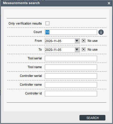
Parameter
Description
Only verification results
Selects only verification results and ignores ordinary measurements.
Count
Number of results found (1-100).
From - To
This parameter refers to the date in which the results were produced. Now users can ignore the date in the search.
Tool serial
Searches for verifications made on a tool with “ToolSerial” serial.
Tool name
Searches for verifications made on a tool with “ToolName” name.
Controller serial
Searches for verifications made with a controller with “ControllerSerial” serial.
Controller name
Searches for verifications made with a controller with “ControllerName” name.
Controller id
Searches for verifications made with a controller with “ControllerId” id.
Insert the relevant information for the search in the boxes.
Click on Search.
Exporting Results
To export a result or a set of results, select a specific result or set of results on the results pane and click on the Export button or right-click.

The following options are available:
Export total database to Excel: To export the complete measurement results database to a .csv file that can be easily opened in MS Excel.
Export selected items to Excel: To export only a set of measurement results previously selected on the measurement results pane to a .csv file.
Create selected verifications pdf: To create a report in .pdf format for a specific verification result. If several verification results are selected at the same time, a .pdf report will be created for each one.
If the measurement result chosen is not a verification result, a minimum of three Free Run measurements must be chosen. You can not mix Free Run measurements and verification results when creating reports.
If several measurement results are selected, a report without limits will be created and each measurement will be shown in a graph.
Creating Measurement Reports
On the Results pane, select a specific result or set of results and click on the Export button.
Select the option Create selected verifications pdf; the Verification Report Information dialogue appears.

Parameter
Description
Customer information
Information related to the customer.
Customer row 1-4
This information will appear at the top right corner of the report.
Tested device id
This information will appear under the tool information and, if the customer has their own id for the tool, it can be entered here.
Service center information
Information related to the service center.
Service row 1-4
This section appears in the middle of report footer. These fields have memory, so the information only needs to be entered once.
Insert the relevant information in the boxes.
Click on Generate to get a report.
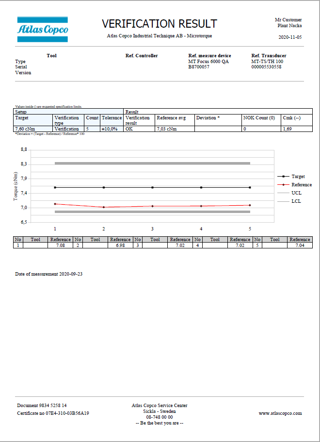
Example of Verification Report 
Example of FreeRun Report
Step results
The step result window shows the step torque and angle values form the latest tightening/loosening.
Events
Events are either errors or information messages that have been raised in the controller. These can be exported to an excel file for storage.
The events window shows a list of the latest 512 events.
Double-click on an event to open a window with information on that event.
Tool settings

Torque check
It is possible to setup an interval that will inform the user that it is time to test and verify the tool by doing a torque check. The interval can either be triggered on number of cycles or on time. With the torque check parameters, it is also possible to lock the tool so that it will not be able to perform any more actions until it has gotten a successful tool verification result.
The verification result is only available if verification is performed via USB Sync together with the MTF6000 IAM QA license.
Transducer settings

Controller settings

Connect controller to ToolsNet
Static mode
Connect the controller to the factory network via Ethernet.
Set Network mode to Static in Controller settings > Configuration > Network.
Set IP-address, subnet mask, gateway to the controller.
Enable ToolsNet.
Set IP-address of ToolsNet server.
Set ToolsNet port, 6700 is the standard port for all MT devices.
Select if the controller should synchronize time with ToolsNet.
DHCP mode
Connect the controller to the factory network via Ethernet.
Set Network mode to DHCP in Controller settings > Configuration > Network.
Enable ToolsNet.
Set IP-address of ToolsNet server.
Set ToolsNet port, 6700 is the standard port for all MT devices.
Select if the controller should synchronize time with ToolsNet.
General settings
GUI object | Description |
Update firmware | Update firmware in a connected controller. The controller must have firmware version 1.4.1 or higher to be able to be updated. |
Set date and time | Set date and time. |
Show vacuum | Opens a window that displays the vacuum pressure value live |
Capture controller screen | Opens a window with a printed replica of what is displayed on the controller screen at that exact moment. Can for instance be used to make operator instructions |
Parameter | Description |
Calibration date | Date of latest calibration. |
Controller name | A user defined name of the controller. |
Controller ID | A user defined identification number of the controller. |
Station name | A user defined station name. |
Station ID | A user defined station identification number. |
Line name | A user defined line name. |
Line ID | A user defined line identification number. |
Controller language |
|
Torque unit | Unit of torque to be displayed in the controller.
|
Temperature unit | The temperature unit to be displayed in the controller. |
Configuration
Parameter | Description |
Beep on OK | If set to enabled the controller will beep on an OK tightening. |
Beep on NOK | If set to enabled the controller will beep on an NOK tightening. |
Beep on Batch complete | If set to enabled the controller will beep when a batch finishes. |
Beep on Batch sequence complete | If set to enabled the controller will beep when a batch sequence finishes. |
Beep on Verification Complete | QA Parameter If set to enabled the controller will beep when a verification is finished. |
Select source | This parameter controls how Psets and batch sequences are selected and activated.
|
Startup mode | At startup select Pset or batch sequence.
|
Pset number | If Pset is selected in Startup mode select Pset number. |
Batch sequence number | If Batch sequence is selected in Startup mode select batch sequence number. |
Startup view | Defines which view in the controller should be opened at start-up. |
Backlight activate on tightening/measurement | If set to yes the controller screen is lit up during a tightening/measurement. |
Lock on error | This parameter enables an event on a tightening error. This event has to be acknowledged before a new tightening can begin. It can be used to stop the system, if for example a robot is running the system. For locking out operators to continue after a failed tightening, a password rule should be enabled. |
Ack on Batch sequence error | Decides if a physical acknowledgment of the Batch sequence error event must be cleared or not. |
Save graphs | Licenced feature Decides if all, none or only failed tightening results should save their graphs. |
Auto start tightening | Automatically starts the active tightening at a given interval. |
Standby | With Standby enabled the controller is set to standby mode after the set time. When the controller wakes up from standby mode no tool initiation is needed. Controller wake up from standby when input from either of the following:
|
Auto shutdown | If enabled, the Auto shutdown parameter can be configured. The user can set a timer for when the battery should turn off if the controller is inactive. |
Tool init. confirmation | Defines if the operator/user needs to press OK before the tool starts initialization. Tool init happens at system start-up and when a tool is connected. |
Tool rehit enabled | Rehit is tightening an already tightened screw. This setting will give a tightening error if the system detects a rehit. |
Current Monitoring | This parameter compares the torque from the transducer with the current used. It only works with MT Focus 6000 with transducerized tools: EDT MT/QMT series.
|
Warning interval | After a set amount of time has passed from the latest torque check a warning will be triggered by the controller that it is time to do a torque check. This event is clearable. |
Warning cycle | After tool has reached the set number of cycles after the latest torque check a warning will be triggered by the controller that it is time to do a torque check. This event is clearable. |
Required interval | After a set amount of time has passed from the latest torque check an error will be triggered by the controller that it is time to do a torque check. Tool will now be locked until an OK Torque check has been performed. |
Required cycles | After tool has reached the set number of cycles after the latest torque check an error will be triggered by the controller that it is time to do a torque check. Tool will now be locked until an OK Torque check has been performed. |
Network mode | Licenced feature.
|
IP address | Enter static IP address of controller. Only available if Network mode is set to Static. |
Subnet mask | Enter static subnet mask address of controller. Only available if Network mode is set to Static. |
Gateway | Enter static gateway address of controller. Only available if Network mode is set to Static. |
DNS 1 | Enter static IP of DNS. |
ToolsNet | Licenced feature. Enable / disable connection with ToolsNet version 8.4 and later. |
ToolsNet IP address | Licenced feature. IP address of ToolsNet server. |
ToolsNet port | Licenced feature. Port of ToolsNet server, 6700 is the standard port for all MT devices. |
ToolsNet sync. time | Licenced feature. Select if the controller should synchronize time with ToolsNet. |
Open protocol |
|
OP Torque unit | Select which torque unit the controller shall send all torque parameters via OP. Only available if Open protocol is set to Enabled.
|
OP Temperature unit | Select which temperature unit the controller shall send all temperature parameters via OP. Only available if Open protocol is set to Enabled.
|
Battery adapter enabled | Yes: Disable all other RS232 parameters and activate compatibility with battery. No: Disable compatibility with battery and activates other RS232 parameters, such as Open Protocol and Scanner. |
RS232 mode | Only available if Battery adapter enabled is set to No.
|
Baudrate | Data transmission rate for RS-232 |
Clear DB on USB export |
|
Operator ID timeout enabled |
|
Operator ID timeout | Operator ID will be cleared after controller has been idle for a set of time. |
Measurement trigger | Licenced feature.
|
Ack on Verification complete | Licenced feature. If Enabled, the user must acknowledge the Verification result popup before continuing. If Disabled, the controller will automatically close the popup when a new measurement starts. |
Zero offset on OK | Licenced feature. If Yes the user can set the zero offset of the transducer by pressing the OK button on the controller. |
QA Custom field count | Licenced feature. Describes what the custom view in the IAM QA controller should look like. How many fields it should display in the view. |
QA Data field 1-4 | Licenced feature. Describes which information to display in the selected field. Possible values:
|
System Info.
Parameter | Description |
Software version |
|
Software date | Build date of the software. |
MAC address | The MAC-address of the IAM. |
Serial number | The controller serial number. |
Licence ID | The licence code. |
License level | The licence level. |
Date and time | Set time and date. |
System Diag.
Parameter | Description |
Current sensor zero |
|
Torque sensor zero |
|
Vacuum pressure |
Network
Parameter | Description |
Link status | Status of the current connection. |
DHCP | Address to configured DHCP. |
IP address | Controller IP address. |
Subnet mask | Subnet mask. |
Gateway | IP for gateway. |
Digital I/O and password settings

Digital I/O
Input signals to the controller.
Parameter | Description |
I/O select mode | Defines if I/O select pins should activate a Pset, Batch sequence or bit selector configuration. |
Digital in
Input signals to the controller.
Parameter | Description |
Disabled | The signal is disabled. |
Start tightening | Starts a tightening, will start on a positive flank (transition 0->1). |
Start tightening (hold) | Starts a tightening, will start on a positive flank (transition 0->1). If the signal is brought low during the tightening, it will be canceled. |
Start loosening | Starts a loosening, will start on a positive flank (transition 0->1). |
Start loosening (hold) | Starts a loosening, will start on a positive flank (transition 0->1). If the signal is brought low during the loosening, it will be canceled. |
Stop operation | Stops any ongoing tightening/loosening. |
Reset | This signal will stop any ongoing tightening. If no tightening is active it will clear the screen from the previous tightening data. |
Disable tool | Set the tool in disabled mode, no new tightening or loosening can be started. |
Initialize tool | Makes the tool run the initial self-calibration. Will amongst other things measure the internal friction. |
Clear event | Will clear a non-blocking controller event. This is the same as acknowledging an error/event by pressing the OK button on the controller. |
Clear all events | Clear all active (non-blocking) controller events. |
Select bit 0-9 | Used to select a Pset, batch sequence or bit selector configuration, if select source is set to digital I/O. |
Reset Batch sequence | Restart a batch sequence. |
Increment Batch | Skip one tightening in a batch. |
Decrement Batch | Redo one tightening in a batch. |
Reset Batch | Restart a batch. |
Batch sequence DI1-12 | Batch sequence input signals. These signals will control the batch sequence input events. |
Standby | Set controller in standby mode to reduce energy consumption |
Reboot | Reboot the controller software. |
Increment Batch sequence | Skip one step in a batch sequence. |
Enable vacuum | Enable vacuum pump |
Enable clean | Revers airflow to clean tube |
Wake up | Wake up controller from standby mode |
Tool guiding light | Turn LED for guiding light on |
Tool status red | Turn LED red on |
Tool status green | Turn LED green on |
Tool status blue | Turn LED blue on |
Tool status white | Turn LED white on |
External monitored 1-8 | Used to manipulate an input without connecting it to a specific function. (Usable for external protocols, such as Open protocol.) |
Start measurement | (Licenced feature) |
Stop measurement | (Licenced feature) |
Start measurement hold | (Licenced feature) |
Set transducer zero | (Licenced feature) |
Reset verification | Reset the verification. |
Digital out
Output signals from the controller.
Parameter | Description |
Disabled | The signal is disabled. |
Ready | The controller is ready to commence tightening. |
Busy | The output is active when the tool is running, either by a tightening or a loosening process. |
Error | An error is active. |
Tightening OK | The tightening program was completed successfully. The signal is inactive as long as the sequence is in process. |
Tightening NOK | The tightening program was not completed successfully. The signal is inactive as long as the sequence is in process. |
Batch complete | The batch step was completed. |
Active event | An event is active. |
Blocking event | An event is preventing operation until resolved. |
Clearable event | Set if an event is acknowledgeable. |
Initializing tool | Indicates that the initial tool self-calibration is ongoing. |
Tool disabled | Indicates if the tool is disabled. |
Vacuum pump | Indicates if the vacuum pump is active. |
Start signal | The output is active, as long as the start lever on the tool is pressed. |
Loosening signal | The output is active, as long as the reverse lever on the tool is pressed. |
Push to start signal | The output is active, as long as the tool bit switch is pressed. |
Batch sequence DO1-8 | Batch sequence output signal. These signals will be controller by batch sequence output events. |
Batch sequence complete | A batch sequence has finished successfully. |
Batch sequence error | Indicates if a batch sequence error was triggered. |
Batch error | Batch failed and was aborted |
Standby active | Controller is in standby mode |
Screw not aligned | Screw not aligned limit has been exceeded. Screw is picked up but not aligned with the bit. |
Screw aligned | Screw aligned limit has been exceeded. Screw is aligned with the bit. |
External monitored 1-10 | Used to manipulate an output without connecting it to a specific function. (Usable for external protocols, such as Open protocol.) |
Vacuum clean | Vacuum clean function is active |
Vacuum pump connected | Checks if Vacuum Pump MT (8432 0854 00) is connected. MTF6000 must have revision C or later version for this signal to operate. |
Measurement OK | (Licenced feature) |
Measurement NOK | (Licenced feature) |
Verification complete | Signal goes high if the verification is completed. |
Verification active | Signal goes high if a verification is active. |
Service required | Tool or transducer is ready for service. |
Battery connected | Battery is connected to the controller. |
Battery low | The battery power has dropped below 20%. |
Verification OK | Verification was successful. |
Verification NOK | Verification failed. |
Unlock bit 0-3 | Indicates which bit to select in the Batch Sequence event step Bit selector. (Calculated binary) |
Torque Check Required | Indicates when a torque check is required. |
Rotating CW | Signal goes high when the tool is rotating clockwise (tightening). |
Rotating CCW | Signal goes high when the tool is rotating counterclockwise (loosening). |
Output signal mode
Tracking - reacts on changes.
Until next tightening - will be active until the next tightening is started.
Duration - will be active for a set amount of time.
Password
This is a licensed feature. Not available on IAM QA.
The flexible password system makes it possible to completely tailor what the operator have access to. Technicians and line managers have the option to gain access to the system via password or by login in via scanner, for example barcode or RFID.
If no password has been configured, the No password configuration will have full access to all functions.
If the password configuration is removed from the IAM MT the controller will generate a new password file where all levels will be fully restricted.
There are different ways to log in and out of the controller:
Enter a PIN code to log in when a padlock symbol is displayed.
Scan a barcode or rfid tag. One scan of the tag to login, scan one more time to log out.
Pushing the OK button.
PIN code
When a function is restricted it will show a pad-lock symbol. Enter the PIN code to unlock the function.
Scanner login
To login in with a barcode or rfid-tag an identifier rule needs to be set-up. This identifier rule has an action that can be set to login, then the level of access is entered.
One scan of the code will login, scan again and the password level will be logged out.
Password settings
General settings
Parameter | Description |
Automatic logout time | Time before the user is automatically logged out from the controller. |
Controller
The Controller table enables you to set access rights.
The four digit PIN code is set in the box below the user number. It is also possible to disable the password for a level by unchecking the Pin enabled box over the password.
Parameter | Description |
Menu access | Accessing the system menu in the controller. |
Change view | Changing from one result view to another. |
Select Pset | Selecting Pset from the controller. |
Select Batch sequence | Selecting batch sequence from the controller. |
Reset tightening error | Acknowledging tightening errors. |
Reset Batch sequence error | Acknowledging batch sequence errors. |
Abort Batch sequence | Reset a batch sequence. |
Increment/decrement Batch sequence | Increase or decrease batch sequence step counter. |
Increment/decrement batch | Increase or decrease batch counter. |
Quick programming | Quick programming access. |
Select source | Change select source |
Tool control | Start/stop tool |
Import settings | Import controller settings (Controller parameters, Pset, batch sequences, Identifiers and I/O settings )via USB flash drive. |
Import software | Update the software. |
Export settings | Export controller settings (Controller parameters, Pset, batch sequences, Identifiers and I/O settings ) to USB flash drive. |
Export results | Export results as CSV-file to USB flash drive. |
Export graphs | Export graphs to USB flash drive. |
Export all | Export everything to USB flash drive. |
Export software | Export software to USB flash drive. |
Export Event | Export events to USB flash drive. |
Controller information | Access of controller information menu. |
Tool information | Access of tool information menu. |
Battery info | Access of battery information menu. |
Connection info | Access to connections menu. |
IP configuration | Access of IP configuration menu. |
ToolsNet configuration | Access of ToolsNet configuration menu. |
Digital I/O | Access of Digital I/O information menu. |
Fieldbus

This function provides the possibility to control the controller from an external source, such as a PLC, together with the Fieldbus Carrier MT.
Fieldbus Carrier MT only works if the Anybus module inside is supported. Only modules coded with an Atlas Copco unique Provider ID are supported, these can only be purchased from Atlas Copco, if the module is purchased from Atlas Copco then it has correct Provider ID. Currently only the following modules are supported:
Anybus M40 PROFINET module 8432085320 (firmware v1.40.01) since MTF6000 firmware 1.12
Anybus M40 EtherCAT module 8432085310 (firmware v2.15.1) since MTF6000 firmware 1.16
Anybus M40 EtherNet/IP module 8432085330 (firmware v1.43.2) since MTF6000 firmware 1.16
Fieldbus Carrier MT is connected to the MTF6000 controller via the fieldbus cable, and to the PLC via an Ethernet cable from the fieldbus module.
Common Fieldbus Carrier MT codes for NS LED on the Anybus PROFINET module:
Off = Offline
Green = Online (RUN)
Red, 1 flash = Station name error
Red, 2 flash = IP Address error
Red, 3 flash = Configuration error
Common Fieldbus Carrier MT codes for the ERR LED on the Anybus EtherCAT module:
Off = No error
Red, Blinking = Invalid configuration
Red, 1 flash = Unsolicited state change
Red, 2 flash = Sync Manager watchdog timeout
Common Fieldbus Carrier MT codes for the MS LED on the Anybus module EtherNet/IP:
Off = No power
Green = Controller by a Scanner in Run state and, if CIP Sync is enabled, time is synchronized to a Grandmaster clock
Green, flashing = Not configured, Scanner in idle state, or, if CIP Sync is enabled, time is synchronized Grandmaster clock
Red = Major fault (EXCEPTION - state, FATAL error etc.)
Red, flashing = Recoverable fault(s). Module is configured, but stored parameters differ from currently used parameters.
Settings
Parameter | Description |
|---|---|
Fieldbus type | The type of fieldbus settings to load. The type must match with the module inside Fieldbus Carrier MT. Support PROFINET from version 1.12.0 and EtherCAT and EtherNet/IP from version 1.16.0. |
Map size | Number of bytes to transfer to/from the controller. The value depends on selected direction in Map settings (To controller/From controller). |
Tool stop at offline | If yes, the tool will be disabled when the fieldbus connection is offline. |
Actual values set
Parameter | Description |
|---|---|
Status | Indicates the status of Fieldbus carrier MT:
Communication between the Fieldbus Carrier MT and the PLC is only available in Active status. |
DHCP enabled | Indicates if DHCP configuration is stored. (PROFINET, EtherNet/IP) |
IP Address | Indicates the IP Address. (PROFINET, EtherNet/IP) |
Subnet mask | Indicates the Subnet mask. (PROFINET, EtherNet/IP) |
Default gateway | Indicates the gateway IP address. (PROFINET, EtherNet/IP) |
Station name | Indicates the station name. (PROFINET) |
Device ID | Indicates identifier number for the device. (EtherCAT) |
Update interval | Indicates how often the fieldbus process data is updated internally. |
Map settings
Select the To Controller tab or the From Controller tab.
Select Add.
The Create signal configuration dialog window opens.
Select the item name in the list to select the item.
Set the item starting position by typing the Byte number in which the least significant Bit should be located.
Set the item starting position by typing the Bit in which the least significant Bit should be located.
Set the Length of the item, expressed in number of bits.
Select Add.
Repeat the above steps for every item to be added.
Opening parameter configuration
Double click a parameter to open the configuration. Or select the check box  for the item and then select OPEN.
Deleting parameter configuration
Select the check box
for the item.To select multi items, press Ctrl on your keyboard and select.
Select DELETE or press Delete on your keyboard.
Moving parameters
It is possible to move parameters by using drag-and-drop in the fieldbus map. The place where the parameter is dropped to indicates the starting position of the parameter.
If a parameter is 1 (or more) bytes then regardless of in which bit position the parameter is dropped it will adjust the starting position to bit 0.
If parameters are overlapped, the parameters will be marked red in both tables.
If an error in the parameter list happened, that error must be solved before being able to save. It is not possible to generate more errors if an error already is in place. That conflict must first be solved.
Data format
General data format description for parameters used in map settings.
Data type (ToolsTalk MT) | Data length (bits) | Data representation | Byte order |
|---|---|---|---|
Boolean | 1 | EtherCAT: 1 BIT PROFINET: 1 bit within an UNSIGNED8 (Generic data module) EtherNet/IP: 1 bit within a BYTE | - |
Boolean | 8 | Array of 8 Booleans EtherCAT: BITARR8 PROFINET: UNSIGNED8 EtherNet/IP: BYTE | - |
Unsigned | 8 | Unsigned Integer, 8 bits (UNSIGNED8, USINT) | - |
Unsigned | 16 | Unsigned Integer, 16 bits (UNSIGNED16, UINT) | EtherCAT/EtherNet/IP: Little-endian (LSB first) PROFINET: Big-endian (MSB first) |
Unsigned | 32 | Unsigned Integer, 32 bits (UNSIGNED32, UDINT) | EtherCAT/EtherNet/IP: Little-endian (LSB first) PROFINET: Big-endian (MSB first) |
Integer | 8 | Signed Integer, 8 bits (INTEGER8, SINT) | - |
Integer | 16 | Signed Integer, 16 bits (INTEGER16, INT) | EtherCAT/EtherNet/IP: Little-endian (LSB first) PROFINET: Big-endian (MSB first) |
Integer | 32 | Signed Integer, 32 bits (INTEGER32, DINT) | EtherCAT/EtherNet/IP: Little-endian (LSB first) PROFINET: Big-endian (MSB first) |
Float | 32 | Floating point number, 32 bits (FLOAT32, REAL) IEEE 754 single precision binary floating point format; 1 sign bit, 8 exponent bits, 23 fractional bits, s eeeeeeee fffffff ffffffff fffffffff | EtherCAT/EtherNet/IP: Little-endian (LSB first) PROFINET: Big-endian (MSB first) |
String | 1..n | UTF-8 encoded string within an array of predefined size (nr of bytes). EtherCAT: UNSIGNED8 array PROFINET: UNSIGNED8 array EtherNet/IP: BYTE array | - |
See Fieldbus Parameter Specification in References for detailed description of available parameters.
PLC configuration (PROFINET)
The module configuration in PLC must match the MTF6000 parameter configuration. Consider the following if the module configuration is done manually in PLC:
All To controller parameters (Output on PLC) must be configured before any From controller parameters (Input on PLC).
Any byte consisting of single bit parameter(s) (Length = 1) must be configured with Generic data module on the PLC. Single bit modules are not supported by the PROFINET protocol whereas the user must keep track of the content of any Generic data modules. Preferable use modules consisting of bit parameter groups (for example, IF 1 – IF 8) instead of single bit parameters (all single bit parameters exists also in a group parameter).
Any byte(s) that are empty in MTF6000 configuration must have Empty data module(s) in the PLC configuration. There are Empty data modules consisting of 1/2/4/8/16/32/64/128 bytes, fill the empty space with modules with as many bytes as possible first and then in decreasing size until the empty space is filled with Empty data modules. Avoid having any empty spaces within the configuration if not needed since it will decrease performance.
Network settings
The network settings can be configured differently depending on which Fieldbus type that is in use, there will be a button in the top right corner if any configuration is available.
EtherCAT
Parameter | Description |
|---|---|
Device ID | Identifier number for the EtherCAT module. |
PROFINET
Configuration of Network settings are not available for PROFINET, these settings can only be configured from external configuration tools.
EtherNet/IP
Parameter | Description |
|---|---|
Network mode | Configure Static IP or DHCP |
IP Address | Configure IP Address, if Network mode is set to Static. |
Subnet mask | Configure Subnet mask, if Network mode is set to Static. |
Default gateway | Configure Default gateway, if Network mode is set to Static. |
Download description
This button can be found in the top right corner and can be used to download a description file (ESI, GSDML, EDS, etc.) of the controller for currently configured Fieldbus type.
Fieldbus Diagnostics
Activate/Deactivate Diagnostics mode
To activate the diagnostics mode simply press the Diagnostic mode enabled button in the top right corner.
Diagnostic mode has two sub-modes:
Forced - used to manipulate and send a specific value to the PLC.
Monitor - is displaying live what the parameter contains.
To deactivate diagnostics mode press the button again (now called Diagnostic mode disabled).
In the List table each parameter will gain a new tab called Diagnostics. This column will display the value of the parameter. Parameters can be displayed as text or as a signal. Signals are displayed as radio buttons. If the radio button is marked that means that the signal is high, if not then the signal is low.
In forced mode the signals will have two radio buttons. On and Off, On means that the signal is high and Off means that the signal is low.
Monitoring mode
Select the Monitor radio button.
View all parameters in the Diagnostic column.
Press the black triangle in the Diagnostics column to expand combined parameters and display the signal of each bit.
Forced mode
Select the Force radio button (Only available when sending data from Controller).
Enter the value of the parameters that should be forced to a different value and press Send frame.
You must press send frame in order to sent the manipulated value to the PLC. The values will not automatically be sent to the PLC just because a parameter value is entered.
Network Update
In the Manage connections menu double-click on Network Update to start the Network update session.
Select Save List to get a template, even if the list is empty.
Fill in the template with correct controller information:
Controller Serial (optional)
Controller Name (optional)
IP Address
Firmware version (optional)
For the controller information that is optional TTMT will collect the information from the controller if connection was successfully established.
Save List
Saves the entered controllers in a csv list that is tab separated. TTMT can read both “;” and tab separated lists.
If no controllers are added the Save List option will create a template with the correct headers that can be filled in externally.
Load list
Loads a csv file into TTMT and displays all controllers in a list.
Check connection
Will check connection for each controller in the list and see if that controller is active on the network.
Status | Description | |
|---|---|---|
| Unknown | Connection has not yet been verified |
| Connection error | Could not connect to the controller. |
| Connection successful | Controller is active and available on the network. |
| Connecting | Checking connection. |


Update program
Only works with tightening controllers.
Save a network update file (*.mtpm).
Open wanted setup in TTMT.
Open Manage connections tab.
Select Save.
Set Save as type to Massupdate file (*.mtpm).
Update several controllers with new configurations.
Select desired *.mtpm file.
Select Open.
Status | Description | |
|---|---|---|
| Unknown | Connection has not yet been verified |
| Error |
|
| OK | Successful program update. |
| Ongoing |
|
When using Network update the TTMT will remove and overwrite all existing Psets, Batch Sequences and Identifiers.
Update firmware
Select FIRMWARE UPDATE and select a .fw file to update ALL controllers in the list with selected firmware.
Status | Description | |
|---|---|---|
| Unknown | Connection has not yet been verified |
| Error |
|
| OK | Successful firmware update. |
| Ongoing |
|
Need to have version 3.2 or higher in order for Network update to work
Add
Enter an IP address to add one controller to the list.
TTMT will automatically start a check connection after the IP address has been added.
Open
Check connection for a specific controller.
Delete
Remove controller form the list.
Troubleshooting
Incorrect trigger on damaged thread error
Cause: Non-continuous self-threading joints might trigger false damaged thread errors due to decreasing torque after the self-threading phase has finished and until the screw head reaches the joint.
Solution: The damaged thread algorithm will not work correctly for these types of joints. We therefore recommend you to set the Damaged thread detection parameter to Disabled.
Incorrect trigger on Rehit
Cause: Rehit is triggered when the controller detects that the screw already has some torque when the tightening begins.
If the screw is inserted to the joint with a lot of side load then the rehit algorithm may falsely trigger the rehit error since the torque will be much higher at startup.
Solution: Try to stabilize the tool and avoid side loads. If the side loads however are necessary then we recommend you to set the Tool rehit enabled parameter to No.
Incorrect seating point
Cause: Incorrect seating point is usually caused by incorrect setup.
Seating can falsely trigger at the beginning of a tightening when the tool goes rapidly from zero to start building some torque, this will make the gradient spike and thus incorrectly trigger a seating detection.
Incorrect seating displacement and gradient trigger can make the seating point appear out of place.
Low speed may cause the gradient torque to be unreadable. (Just like riding a bicycle, the slower you pedal the more you will sway, increasing the speed a little will create a straighter path.)
Solution:
If seating is triggered at the beginning of the tightening you must first add an angle or thread engagement step of 100° prior to the TSM or SCS step to get past the gradient spike at the beginning.
If seating is just off mark then the setup might be incorrect. This is how to properly setup the strategy:
Create a two-step tightening:
Step 1: Angle (or thread engagement) step of 100°.
Step 2: TSM/SCS.
Set the desired target and run a tightening.
Open the tightening graph in analysis.
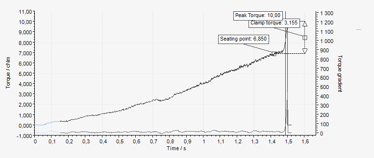
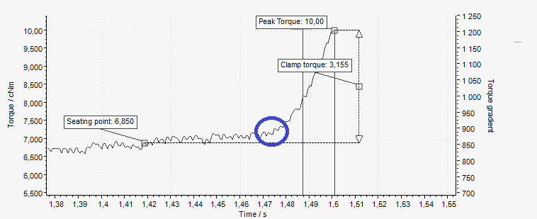
Check the gradient trigger point. The trigger point should be triggered about halfway through the clamping torque. This limit is based on the Torque gradient. If the trigger point is not OK, increase/decrease it to match the tightening. Redo tightening until the gradient trigger point is OK.
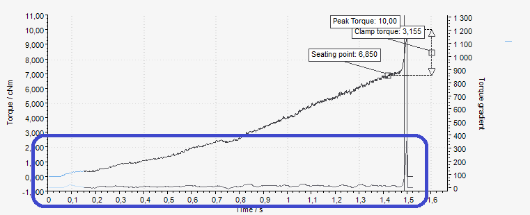
Change the seating angle displacement:
If the seating point is triggered Before the correct seating point, the seating angle displacement parameter should be decreased.
If the seating point is triggered After the correct seating point, the seating angle displacement parameter should be increased.
In the example above, the seating was triggered before the correct seating point. Therefore, the seating angle displacement should be decreased.
Redo tightening and tweak the seating angle displacement until it is set at the correct seating point.
If seating is still triggered at the beginning of the step, even if an angle/thread engagement step of 100° comes before it, the speed might be too low. If the gradient is incorrect, increase the speed and try again.
Graph gets a dip and loses torque in the middle of the tightening.
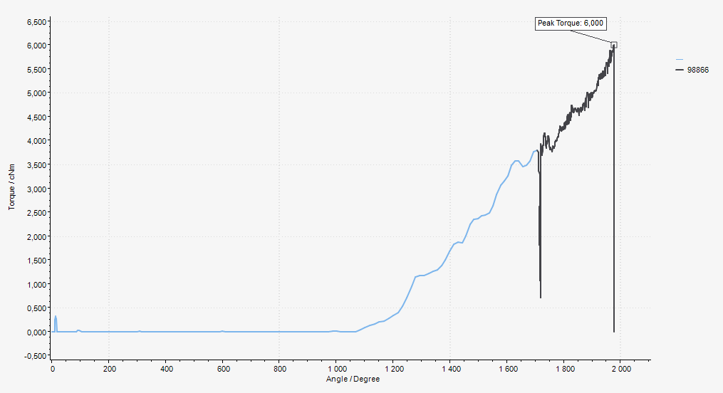
Cause: This is caused by the fact that the angle step, prior to the torque step, is starting to tighten the screw. The “dip” happens when the tool goes from a very high speed to a lower speed while building torque.
Solution: The angle step used as rundown should always end before the screw finds seating.
To avoid this type of tightenings make sure to lower the target angle so it doesn’t exceeds the seating point.
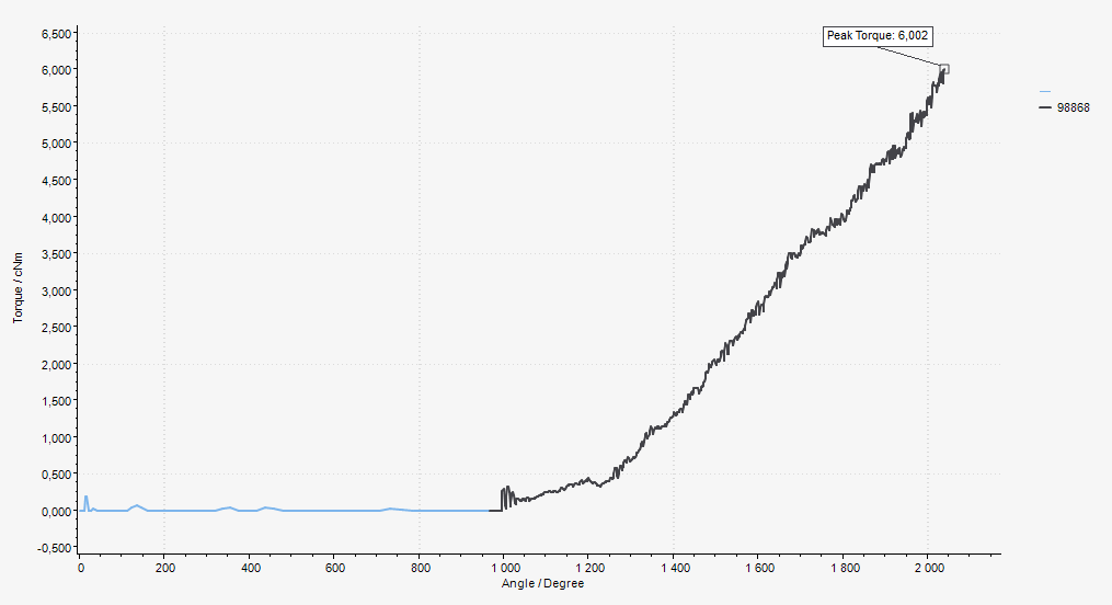
This tightening is the same as above except that the angle step has a lower target angle and stops before the screw finds seating. Now the dip is gone.
Cannot connect to ToolsNet 8
Cause: There can be a number of different reasons as to why the MTF6000 controller doesn’t connect to ToolsNet 8 but the most common is an incorrect setup of the network settings.
Solution:
Check that the ToolsNet IP address is the same as the ToolsNet 8 server IP address.
Check that the Controller IP address is not the same as the ToolsNet IP address.
Check that the Controller IP address is unique.
Check that the Subnet mask is correct.
Check that the Gateway IP address is correct.
Check that the ToolsNet port is correct. ToolsNet 8 is using port 6700 as default for MTF6000.
Check that the controller and ToolsNet 8 server is on the same network.
To test this:
Open the command prompt (press windows start -> enter “cmd”).
Write “ping xxx.xxx.xxx.xxx” (where xxx.xxx.xxx.xxx is the controller IP address).
Check for the response.
Write “ping yyy.yyy.yyy.yyy” (where yyy.yyy.yyy.yyy is the ToolsNet server IP address).
Check for the response.
The following response shows an example of successful access:
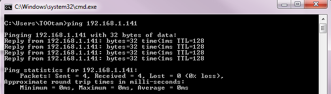
If both the controller and the ToolsNet server can be accessed, the issue is not in the network settings but rather in the services of ToolsNet 8.
The following services must be running for ToolsNet 8 to be able to communicate with the MTF6000:
License server
Data collection service
Protocol interface module
Internet information services
Data communication services
This response is shown if the controller cannot be accessed:

If the controller cannot be accessed it is an issue in the network setup.
Check again that the controller is connected to the same network as the ToolsNet 8 server and that the IP, mask and gateway are correct.
References
Event codes
Error code | Event information | Instruction |
|---|---|---|
101 | Supply voltage exceeded | Check power supply. |
102 | Supply voltage too low | Check power supply. |
103 | Internal 24V exceeded | Disconnect external equipment. |
104 | Internal 24V too low | Disconnect external equipment. |
105 | Internal 12V exceeded | Disconnect tool if connected. |
106 | Internal 12V too low | Disconnect tool if connected. |
107 | Internal 5V exceeded | Disconnect tool if connected. |
108 | Internal 5V too low | Disconnect tool if connected. |
109 | External 24V error | Disconnect external equipment, restart controller. |
110 | DC/DC temperature error | Replace the controller. |
111 | I/O expanders reinitialized | Press OK to continue. |
112 | Failed to reinitialize I/O | Restart the controller. |
113 | Power fault | Check power supply. |
120 | Zero offset error, Current | Replace the controller. |
121 | Zero offset error, Sensor | Replace the tool transducer or the tool. |
122 | Motor current low | Replace the tool. |
123 | Motor current exceeded | Replace the tool. |
124 | Motor driver voltage too low | Replace the tool. |
125 | Motor driver short circuit | Replace the tool. |
126 | Motor driver temperature exceeded | Replace the tool. |
127 | Motor driver open load | Replace the tool. |
128 | Motor driver fault | Restart the controller. |
130 | EEPROM read error | Replace the controller. |
131 | EEPROM write error | Replace the controller. |
132 | Internal hardware error | Replace the controller. |
133 | File system error | Replace IAM MT. |
134 | USB host overcurrent | Disconnect USB devices. |
135 | USB flash drive volume error | Try another USB flash drive. |
140 | No tool connected | Connect tool. |
141 | Tool not supported | Connect supported tool. |
142 | Tool communication error | Replace the tool. |
143 | Tool 5V error | Replace the tool. |
144 | Tool 12V error | Replace the tool. |
150 | Tool initializing error | Check that the tool is running freely during start up. |
151 | Friction too high | Check that the tool is running freely during start up. |
152 | Tool angle encoder error | Connect tool. |
153 | Tool direction error | Connect tool. |
154 | Bit was blocked | Check that the tool is running freely during start up. |
155 | Tool motor temperature exceeded | Allow time for tool to cool down. |
156 | Tool not supported | Transducerized tools not supported by current license. |
157 | Failed to update tool software | Disconnect transducer. |
158 | Tool initialization error | |
159 | Torque measurement warning | Calibrate the tool. |
160 | Torque measurement error | Calibrate the tool. |
201 | Runtime parameter error | Restart the controller. |
202 | Invalid controller parameters | Replace IAM MT. |
203 | Invalid controller parameters | Replace the tool |
204 | Invalid I/O parameters | Replace IAM MT. |
205 | Invalid identifier parameters | Replace IAM MT. |
206 | Invalid Pset parameters | Replace IAM MT. |
207 | Invalid Batch sequence parameters | Replace IAM MT. |
208 | Invalid password parameters | Replace IAM MT. |
209 | Tool statistics error. | Replace the tool. |
210 | Unable to load fonts from IAM MT | Replace IAM MT. |
211 | Invalid tool configuration parameters | Replace IAM MT. |
212 | Invalid operator parameters | Replace IAM MT. |
220 | Result database error | Replace IAM MT. |
221 | Graph database error | Replace IAM MT. |
225 | Reset result database | Result database was reset. |
226 | Reset graph database | Graph database was reset. |
227 | No results to export - database empty | |
228 | Old results removed | |
229 | Old graphs removed | |
230 | Pset not configured for connected tool | Select another Pset or configure new Pset in ToolsTalk MT. |
231 | Select error source | Change select source. Can be changed in ToolsTalk MT Controller settings. |
232 | Select error busy | Wait until tool is not running. |
240 | Network configuration has an error | Change network configuration. |
241 | IP address and gateway not in same subnet | Change network configuration. |
301 | Tool connected | Press OK to initialize the tool. |
302 | Tool initializing | Please wait. |
303 | Tool software updating | Please wait. |
304 | Tool software update error | Check tool cable or replace the tool. |
305 | Tool calibration required | Calibrate the tool. |
306 | Service required | Tool calibration has expired. Calibrate the tool. |
310 | Software has been updated | Press OK to continue. |
311 | Software file wasn't found on USB | Copy software file to USB flash drive. |
312 | Software update failed | Software file on USB may be broken. Update software file on USB and try again. |
313 | Copying software | Please wait. Software is being copied to/from USB. |
314 | Can only show first 20 .mtp or .fw files | Press OK to continue. |
315 | Software update failed - incompatible hardware | |
320 | Login expired | User was logged out. |
321 | User has logged in | |
322 | The current user has logged out | |
350 | Battery adapter hardware error | |
351 | Battery adapter temperature exceeded | Let battery to cool down. |
352 | Battery adapter charge fault | Change battery. |
353 | Battery temperature error | Let battery to cool down. |
354 | Battery discharge error | Connect PSU to charge battery. |
355 | Battery charge critically low | Connect PSU to charge battery. |
356 | Battery not supported | Change battery. |
357 | Battery adapter charge fault | Change battery. |
358 | Battery adapter charge fault | Let battery cool down or change battery. |
401 | Tightening error | Press OK to continue |
402 | Batch sequence error | Press OK to continue |
403 | Batch sequence parameter error | Check controller to see which parameter is incorrect |
404 | Pset not supported | Select another Pset |
405 | Pset parameter error | Update Pset. |
507 | ToolsNet skipped result | |
601 | Controller communication error | |
602 | Transducer communication error | |
603 | Measurement data lost due to lost USB link | |
604 | Transducer connected | |
605 | No transducer detected | Connect transducer and try again. |
606 | Remote device is busy | Try again later. |
607 | Transducer service required | |
608 | Zero offset error, Transducer | Check that the transducer cable is fastened correctly or replace cable/transducer. |
609 | Operator ID required by active verification | Scan operator ID. |
610 | Connected device is not compatible with QA | |
701 | Fieldbus not supported by controller HW | Replace controller with rev C or higher. |
702 | Invalid fieldbus parameters | Replace IAM MT. |
703 | Fieldbus module error | Check fieldbus cable or replace the fieldbus module, press OK to continue. |
704 | Fieldbus driver warning | Check for firmware update, press OK to continue. |
705 | Fieldbus driver error | Check for firmware update. |
706 | Fieldbus module in error state | Check fieldbus network status. |
707 | Fieldbus module in exception state | Check for firmware update. |
720 | Fieldbus module not connected | Connect fieldbus module, check fieldbus cable or replace the fieldbus module. |
721 | Fieldbus module not supported, wrong module type | Connect supported fieldbus module. |
722 | Fieldbus module not supported, wrong network type | Connect supported fieldbus module. |
723 | Fieldbus module not supported, wrong provider ID | Connect supported fieldbus module. |
724 | Fieldbus module not supported, FW version not approved | Connect supported fieldbus module. |
730 | Fieldbus not configured for connected module | Change configuration of fieldbus type or connect correct module. |
731 | Fieldbus parameter error | Update fieldbus parameters and press OK. |
732 | Fieldbus configuration of network settings failed | Check that fieldbus setup is ok and try again. |
740 | Max 128 submodules supported for Profinet | Update fieldbus parameters and press OK. |
741 | Profinet station name syntax error | Update fieldbus parameters and press OK. |
901 | IAM MT not present | Insert IAM MT. |
902 | Failed to initialize IAM MT | Restart controller or change IAM MT. |
903 | IAM MT read error | Check that the FW file on the IAM MT root is named exactly MTF6000.FW (manually from PC). Otherwise replace the IAM MT. |
904 | IAM MT write error | Replace IAM MT. |
905 | Invalid software on IAM MT | Update software on IAM MT (manually from PC). |
906 | Flash programming error | Replace the controller. |
907 | Invalid license on IAM MT | Update software on IAM MT (manually from PC) to a newer version that support the IAM license. Otherwise replace the IAM MT. |
908 | Incompatible software version | Update software on IAM MT (manually from PC) to a newer version that supports the HW. Otherwise replace the IAM MT. |
990 | External event | |
991 | External event | |
992 | External event |
Tightening error codes
Tightening error | Description |
|---|---|
Trigger lost | Tool trigger released before tightening was done. |
Bit slip detected | The bit slipped out of the screw. It is recommended to replace the bit if this occurs often. (Can be enabled/disabled per Pset). Please note that this should not be turned off in Seating control steps because it may cause erroneous(false) seating triggers. |
Damaged thread detected | The thread has been damaged and the screw cannot build up any more torque. |
Re-hit detected | A screw was re-tightened. This can be enabled/disabled per Pset. |
Seating was not detected | No seating point was detected. |
Total time exceeded | The global maximum time limit for the tightening was exceed. |
Global time not reached | The global minimum time limit for the tightening was not reached. |
Time exceeded | The Pset step maximum time limit for the tightening was exceed. |
Time not reached | The Pset step minimum time limit for the tightening was not reached. |
Torque high | The Pset maximum torque limit was exceeded. |
Torque low | The Pset minimum torque limit was not reached. |
Angle high | The Pset maximum angle limit was exceeded. |
Angle low | The Pset minimum angle limit was not reached. |
Total angle high | The global maximum angle limit for the Pset was exceed. |
Total angle low | The global minimum angle limit for the Pset was not reached. |
Tightening angle high | The torque step maximum tightening angle was exceeded. The tightening angle is the angle from the angle trigger torque to the target torque. |
Tightening angle low | The torque step minimum tightening angle was not reached. The tightening angle is the angle from the angle trigger torque to the target torque. |
Seating angle high | The maximum clamp angle was exceeded. This can only happen in a Seating control step or a Torque seating monitoring step. The clamp angle is the angle from seating to finished tightening. |
Seating angle low | The minimum clamp angle was not reached. This can only happen in a Seating control step or a Torque seating monitoring step. The clamp angle is the angle from seating to finished tightening. |
Seating torque high | The maximum clamp torque was not reached. This can only happen in a Seating control step or a Torque seating monitoring step. The clamp torque is the torque from seating to finished tightening. |
Seating torque low | The minimum clamp torque was not reached. This can only happen in a Seating control step or a Torque seating monitoring step. The clamp torque is the torque from seating to finished tightening. |
Clamp angle low | Clamp angle is above upper limit. |
Clamp angle high | Clamp angle is below lower limit. |
Clamp torque high | Clamp torque is above upper limit. |
Clamp torque low | Clamp torque is below lower limit. |
Rescinding torque error | Torque dropped below rescinding torque limit during tightening |
Quick network guide
What is IP address
IP address is a unique identifier for each device on the network, two different devices cannot have the exact same IP address. The IP address combined with the subnet mask decides which devices that can communicate with each other.
How does Subnet mask work
Subnet mask is the identifier used to tell each device who they can communicate with on the network. The following table shows where everything is marked to visually display which devices that can communicate to each other depending on the subnet mask.
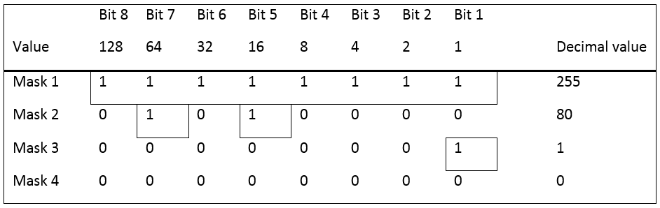
Question: With subnet mask 255, which controllers can communicate with each other?

Answer: With subnet mask 255, all bits must have the same value. That means that IP 1 and 5, IP 3 and 6 can communicate with each other.
Question: With subnet mask 80, which controllers can communicate with each other?

Answer: With subnet mask 80, bit 7 and 5 must have the same value. That means that IP 1, 3, 5 and 6 can communicate with each other.
Question: With subnet mask 1, which controllers can communicate with each other?

Answer: With subnet mask 1, bit 1 must have the same value. That means that IP 1, 3, 5 and 6, IP 2 and 4 can communicate with each other.
Question: With subnet mask 0, which controllers can communicate with each other?
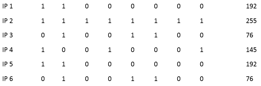
Answer: With subnet mask 0, 0 bits must have the same value. That means that all IP addresses can communicate with each other.
Correct settings
Here are some examples on the correct ways to setup the MTF6000 and ToolsNet server communication.
Each IP address is built of 4 parts, all containing 8 bits and must match the corresponding subnet mask. The easiest and most common setup is to have the three first parts exactly the same with subnet mask 255.255.255.0. This means that the last part can be any number between 0-255.

Part | Subnet mask | IP address | Gateway | ToolsNet | Match |
|---|---|---|---|---|---|
1 | 255 | 192 | 192 | 192 | Full Match |
2 | 255 | 168 | 168 | 168 | Full Match |
3 | 255 | 1 | 1 | 1 | Full Match |
4 | 0 | 60 | 1 | 100 | No match needed |
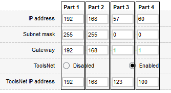
Part | Subnet mask | IP address | Gateway | ToolsNet | Match |
|---|---|---|---|---|---|
1 | 255 | 192 | 192 | 192 | Full Match |
2 | 255 | 168 | 168 | 168 | Full Match |
3 | 0 | 57 | 1 | 123 | No match needed |
4 | 0 | 60 | 1 | 100 | No match needed |
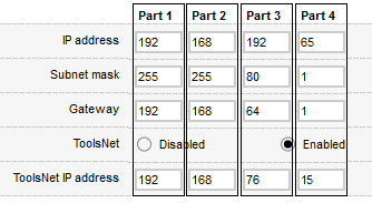
Part | Subnet mask | IP address | Gateway | ToolsNet | Match |
|---|---|---|---|---|---|
1 | 255 | 192 | 192 | 192 | Full Match |
2 | 255 | 168 | 168 | 168 | Full Match |
3 | 80 | 192 | 64 | 76 | Full match for bit 5 and 7 |
4 | 1 | 60 | 1 | 100 | Full match for bit 1 |
Incorrect settings
Here are some examples on the incorrect ways to setup the MTF6000 and ToolsNet server communication.
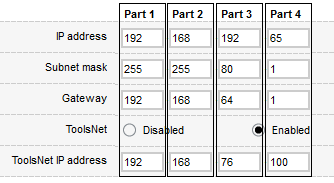
Part | Subnet mask | IP address | Gateway | ToolsNet | Match |
|---|---|---|---|---|---|
1 | 255 | 192 | 192 | 192 | Full Match |
2 | 255 | 168 | 168 | 168 | Full Match |
3 | 80 | 192 | 64 | 76 | Full match for bit 5 and 7 |
4 | 1 | 65 | 1 | 100 | No match for bit 1 |


Part | Subnet mask | IP address | Gateway | ToolsNet | Match |
|---|---|---|---|---|---|
1 | 255 | 192 | 192 | 10 | No match for bit 8, 7, 4 and 2 |
2 | 255 | 168 | 168 | 46 | No match for bit 8, 3 and 2 |
3 | 255 | 1 | 1 | 5 | No match for bit 3 |
4 | 0 | 60 | 1 | 37 | No match needed |
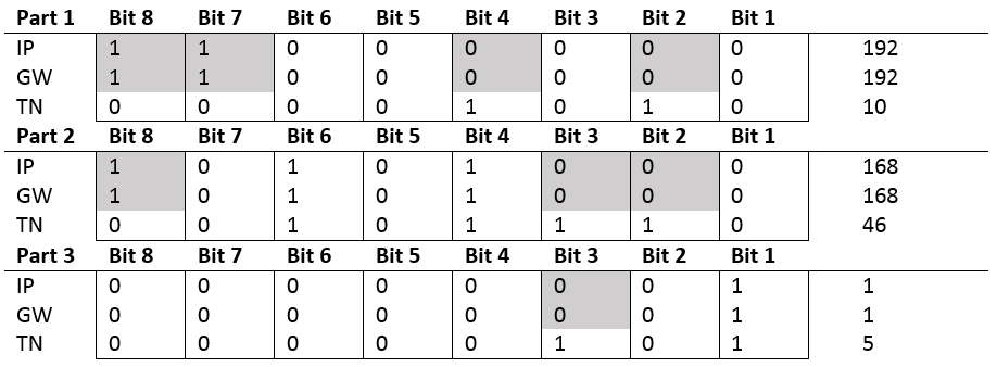
Fieldbus Parameter Specification
ID | Parameter | Data type | Bit length | Array length Range as: Min Max Default | Unit type | Comments |
|---|---|---|---|---|---|---|
10 | Select mode | Unsigned | 8 | 1 | - | 1 = Pset 2 = Batch Sequence |
11 | Select number | Unsigned | 16 | 1 | - | |
12 | Identifier download command | Unsigned | 8 | 1 | - | |
13 | Identifier download data | String | 8 | 10;250;30 | - | |
103 | SW Version | Unsigned | 8 | 4 | - | a.b.c.d [0] = a [1] = b [2] = c [3] = d |
104 | SW Date | String | 8 | 19 | - | YYYY-MM-DDThh:mm:ss Valid dates between 2000-2099 |
105 | MAC Address | Unsigned | 8 | 6 | - | AA-BB-CC-DD-EE-FF [0] = AA [1] = BB [2] = CC [3] = DD [4] = EE [5] = FF |
106 | Serial number | String | 8 | 8 | - | |
107 | Production date | String | 8 | 19 | - | YYYY-MM-DDThh:mm:ss Valid dates between 2000-2099 |
108 | License ID | Unsigned | 32 | 1 | - | |
109 | License level | Unsigned | 8 | 1 | - | 10 = 'IAM Workstation' 20 = 'IAM Process' 30 = 'IAM Automation' 40 = 'IAM QA' |
110 | Date and time | String | 8 | 19 | - | YYYY-MM-DDThh:mm:ss Valid dates between 2000-2099 |
111 | Controller status | Unsigned | 8 | 1 | - | 0 = 'Initializing' 1 = 'Ready' 2 = 'Calibration mode' |
112 | HW Version | Unsigned | 8 | 1 | - | |
120 | Active event count | Unsigned | 8 | 1 | - | |
121 | Active event ID | Unsigned | 16 | 1 | - | |
122 | Active event severity | Unsigned | 8 | 1 | - | 0 = 'No active event' 1 = 'Information' 2 = 'Warning' 3 = 'Error' |
123 | Active event datetime | String | 8 | 19 | - | YYYY-MM-DDThh:mm:ss Valid dates between 2000-2099 |
124 | Active event text | String | 8 | 10;100;30 | - | |
210 | Vacuum pressure sensor | Float | 32 | 1 | kPa | |
300 | Tool status | Unsigned | 8 | 1 | - | 0 = 'Not present' 1 = 'Connected' 2 = 'Initializing' 3 = 'Ready' 4 = 'Error!' |
304 | Tool serial number | String | 8 | 8 | - | |
305 | Tool temperature | Float | 32 | 1 | °C | |
306 | Tool friction at 100 rpm | Float | 32 | 1 | mNm | |
307 | Tool friction at max rpm | Float | 32 | 1 | mNm | |
401 | Realtime torque | Float | 32 | 1 | mNm | |
402 | Realtime peak torque | Float | 32 | 1 | mNm | |
403 | Realtime angle | Float | 32 | 1 | ° | |
500 | Selected pset | Unsigned | 16 | 1 | - | |
501 | Selected batch sequence | Unsigned | 16 | 1 | - | |
502 | Pset step count | Unsigned | 8 | 1 | - | |
503 | Pset step number | Unsigned | 8 | 1 | - | |
504 | Batch sequence step count | Unsigned | 16 | 1 | - | |
505 | Batch sequence step number | Unsigned | 16 | 1 | - | |
506 | Active batch count | Unsigned | 16 | 1 | - | |
507 | Active batch index | Unsigned | 16 | 1 | - | |
600 | Link status | Unsigned | 8 | 1 | - | 0 = 'Stopped' 1 = 'Link down' 2 = 'Identifying' 3 = 'Configured' |
602 | IP Address | Unsigned | 32 | 1 | - | |
603 | IP Subnet mask | Unsigned | 32 | 1 | - | |
604 | IP Gateway | Unsigned | 32 | 1 | - | |
800 | Tool cycle count | Unsigned | 32 | 1 | - | |
801 | Tool OK count | Unsigned | 32 | 1 | - | |
802 | Tool NOK count | Unsigned | 32 | 1 | - | |
803 | Tool avg torque | Float | 32 | 1 | mNm | |
804 | Tool avg temperature | Float | 32 | 1 | °C | |
805 | Tool avg max speed | Float | 32 | 1 | rpm | |
806 | Tool avg trq over angle | Float | 32 | 1 | mNm/° | |
807 | Tool avg cycle duration | Float | 32 | 1 | s | |
820 | Tool lifetime cycle count | Unsigned | 32 | 1 | - | |
821 | Tool lifetime OK count | Unsigned | 32 | 1 | - | |
822 | Tool lifetime NOK count | Unsigned | 32 | 1 | - | |
823 | Tool lifetime avg torque | Float | 32 | 1 | mNm | |
824 | Tool lifetime avg temp | Float | 32 | 1 | °C | |
825 | Tool lifetime avg max speed | Float | 32 | 1 | rpm | |
826 | Tool lifetime avg trq over angle | Float | 32 | 1 | mNm/° | |
827 | Tool lifetime avg cycle duration | Float | 32 | 1 | s | |
900 | Scanned barcode | String | 8 | 10;250;30 | - | |
1000 | TN status | Unsigned | 8 | 1 | - | 0 = 'Stopped' 1 = 'Link down' 2 = 'Identifying' 3 = 'Configured' |
1001 | TN result queue | Unsigned | 32 | 1 | - | |
2000 | DI 1 | Boolean | 1 | 1 | - | |
2001 | DI 2 | Boolean | 1 | 1 | - | |
2002 | DI 3 | Boolean | 1 | 1 | - | |
2003 | DI 4 | Boolean | 1 | 1 | - | |
2004 | DI 5 | Boolean | 1 | 1 | - | |
2005 | DI 6 | Boolean | 1 | 1 | - | |
2006 | DI 7 | Boolean | 1 | 1 | - | |
2007 | DI 8 | Boolean | 1 | 1 | - | |
2008 | DI 9 | Boolean | 1 | 1 | - | |
2009 | DI 10 | Boolean | 1 | 1 | - | |
2010 | DI 11 | Boolean | 1 | 1 | - | |
2011 | DI 12 | Boolean | 1 | 1 | - | |
2012 | Not available | Boolean | 1 | 1 | - | |
2013 | Not available | Boolean | 1 | 1 | - | |
2014 | Not available | Boolean | 1 | 1 | - | |
2015 | Not available | Boolean | 1 | 1 | - | |
2050 | DI 1 - DI 8 | Boolean | 1 | 8 | - | 0=2000 1=2001 2=2002 3=2003 4=2004 5=2005 6=2006 7=2007 |
2051 | DI 9 - DI 12 | Boolean | 1 | 8 | - | 0=2008 1=2009 2=2010 3=2011 |
2100 | DO 1 | Boolean | 1 | 1 | - | |
2101 | DO 2 | Boolean | 1 | 1 | - | |
2102 | DO 3 | Boolean | 1 | 1 | - | |
2103 | DO 4 | Boolean | 1 | 1 | - | |
2104 | DO 5 | Boolean | 1 | 1 | - | |
2105 | DO 6 | Boolean | 1 | 1 | - | |
2106 | DO 7 | Boolean | 1 | 1 | - | |
2107 | DO 8 | Boolean | 1 | 1 | - | |
2150 | DO 1 - DO 8 | Boolean | 1 | 8 | - | 0=2100 1=2101 2=2102 3=2103 4=2104 5=2105 6=2106 7=2107 |
2200 | CF Start tightening | Boolean | 1 | 1 | - | |
2201 | CF Start tightening hold | Boolean | 1 | 1 | - | |
2202 | CF Start loosening | Boolean | 1 | 1 | - | |
2203 | CF Start loosening hold | Boolean | 1 | 1 | - | |
2204 | CF Stop operation | Boolean | 1 | 1 | - | |
2205 | CF Reset | Boolean | 1 | 1 | - | |
2206 | Not available | Boolean | 1 | 1 | - | |
2207 | CF Disable tool | Boolean | 1 | 1 | - | |
2208 | CF Initialize tool | Boolean | 1 | 1 | - | |
2209 | Not available | Boolean | 1 | 1 | - | |
2210 | CF Clear event | Boolean | 1 | 1 | - | |
2211 | CF Clear all events | Boolean | 1 | 1 | - | |
2212 | Not available | Boolean | 1 | 1 | - | |
2213 | Not available | Boolean | 1 | 1 | - | |
2214 | Not available | Boolean | 1 | 1 | - | |
2215 | Not available | Boolean | 1 | 1 | - | |
2216 | Not available | Boolean | 1 | 1 | - | |
2217 | Not available | Boolean | 1 | 1 | - | |
2218 | Not available | Boolean | 1 | 1 | - | |
2219 | Not available | Boolean | 1 | 1 | - | |
2220 | Not available | Boolean | 1 | 1 | - | |
2221 | CF Reset batch sequence | Boolean | 1 | 1 | - | |
2222 | CF Increment batch | Boolean | 1 | 1 | - | |
2223 | CF Decrement batch | Boolean | 1 | 1 | - | |
2224 | CF Reset batch | Boolean | 1 | 1 | - | |
2225 | CF Batch Sequence DI1 | Boolean | 1 | 1 | - | |
2226 | CF Batch Sequence DI2 | Boolean | 1 | 1 | - | |
2227 | CF Batch Sequence DI3 | Boolean | 1 | 1 | - | |
2228 | CF Batch Sequence DI4 | Boolean | 1 | 1 | - | |
2229 | CF Batch Sequence DI5 | Boolean | 1 | 1 | - | |
2230 | CF Batch Sequence DI6 | Boolean | 1 | 1 | - | |
2231 | CF Batch Sequence DI7 | Boolean | 1 | 1 | - | |
2232 | CF Batch Sequence DI8 | Boolean | 1 | 1 | - | |
2233 | CF Batch Sequence DI9 | Boolean | 1 | 1 | - | |
2234 | CF Batch Sequence DI10 | Boolean | 1 | 1 | - | |
2235 | CF Batch Sequence DI11 | Boolean | 1 | 1 | - | |
2236 | CF Batch Sequence DI12 | Boolean | 1 | 1 | - | |
2237 | CF Standby | Boolean | 1 | 1 | - | |
2238 | CF Reboot | Boolean | 1 | 1 | - | |
2239 | CF Increment batch sequence | Boolean | 1 | 1 | - | |
2240 | Not available | Boolean | 1 | 1 | - | |
2241 | CF Enable vacuum | Boolean | 1 | 1 | - | |
2242 | CF Enable clean | Boolean | 1 | 1 | - | |
2243 | CF Wake up | Boolean | 1 | 1 | - | |
2244 | CF Tool guiding light | Boolean | 1 | 1 | - | |
2245 | CF Tool status red | Boolean | 1 | 1 | - | |
2246 | CF Tool status green | Boolean | 1 | 1 | - | |
2247 | CF Tool status blue | Boolean | 1 | 1 | - | |
2248 | CF Tool status white | Boolean | 1 | 1 | - | |
2249 | CF External monitored 1 | Boolean | 1 | 1 | - | |
2250 | CF External monitored 2 | Boolean | 1 | 1 | - | |
2251 | CF External monitored 3 | Boolean | 1 | 1 | - | |
2252 | CF External monitored 4 | Boolean | 1 | 1 | - | |
2253 | CF External monitored 5 | Boolean | 1 | 1 | - | |
2254 | CF External monitored 6 | Boolean | 1 | 1 | - | |
2255 | CF External monitored 7 | Boolean | 1 | 1 | - | |
2256 | CF External monitored 8 | Boolean | 1 | 1 | - | |
2257 | Not available | Boolean | 1 | 1 | - | |
2258 | Not available | Boolean | 1 | 1 | - | |
2259 | Not available | Boolean | 1 | 1 | - | |
2260 | Not available | Boolean | 1 | 1 | - | |
2261 | Not available | Boolean | 1 | 1 | - | |
2262 | Not available | Boolean | 1 | 1 | - | |
2263 | Not available | Boolean | 1 | 1 | - | |
2264 | CF Reset verification | Boolean | 1 | 1 | - | |
2265 | Reserved | Boolean | 1 | 1 | - | |
2266 | Reserved | Boolean | 1 | 1 | - | |
2267 | Reserved | Boolean | 1 | 1 | - | |
2268 | Reserved | Boolean | 1 | 1 | - | |
2269 | Reserved | Boolean | 1 | 1 | - | |
2270 | Reserved | Boolean | 1 | 1 | - | |
2271 | Reserved | Boolean | 1 | 1 | - | |
2272 | Reserved | Boolean | 1 | 1 | - | |
2400 | CF 1 - CF 8 | Boolean | 1 | 8 | - | 0=2200 1=2201 2=2202 3=2203 4=2204 5=2205 7=2207 |
2401 | CF 9 - CF 16 | Boolean | 1 | 8 | - | 0=2208 2=2210 3=2211 |
2402 | CF 17 - CF 24 | Boolean | 1 | 8 | - | 5=2221 6=2222 7=2223 |
2403 | CF 25 - CF 32 | Boolean | 1 | 8 | - | 0=2224 1=2225 2=2226 3=2227 4=2228 5=2229 6=2230 7=2231 |
2404 | CF 33 - CF 40 | Boolean | 1 | 8 | - | 0=2232 1=2233 2=2234 3=2235 4=2236 5=2237 6=2238 7=2239 |
2405 | CF 41 - CF 48 | Boolean | 1 | 8 | - | 1=2241 2=2242 3=2243 4=2244 5=2245 6=2246 7=2247 |
2406 | CF 49 - CF 56 | Boolean | 1 | 8 | - | 0=2248 1=2249 2=2250 3=2251 4=2252 5=2253 6=2254 7=2255 |
2407 | CF 57 - CF 64 | Boolean | 1 | 8 | - | 0=2256 |
2408 | CF 65 - CF 72 | Boolean | 1 | 8 | - | 0=2264 |
2500 | RF Ready | Boolean | 1 | 1 | - | |
2501 | RF Busy | Boolean | 1 | 1 | - | |
2502 | RF Error | Boolean | 1 | 1 | - | |
2503 | RF Tightening OK | Boolean | 1 | 1 | - | |
2504 | RF Tightening NOK | Boolean | 1 | 1 | - | |
2505 | RF Batch complete | Boolean | 1 | 1 | - | |
2506 | RF Active event | Boolean | 1 | 1 | - | |
2507 | RF Blocking event | Boolean | 1 | 1 | - | |
2508 | RF Clearable event | Boolean | 1 | 1 | - | |
2509 | RF Initializing tool | Boolean | 1 | 1 | - | |
2510 | RF Tool disabled | Boolean | 1 | 1 | - | |
2511 | RF Vacuum pump | Boolean | 1 | 1 | - | |
2512 | RF Start signal | Boolean | 1 | 1 | - | |
2513 | RF Loosening signal | Boolean | 1 | 1 | - | |
2514 | RF Push to start signal | Boolean | 1 | 1 | - | |
2515 | RF Batch Sequence DO1 | Boolean | 1 | 1 | - | |
2516 | RF Batch Sequence DO2 | Boolean | 1 | 1 | - | |
2517 | RF Batch Sequence DO3 | Boolean | 1 | 1 | - | |
2518 | RF Batch Sequence DO4 | Boolean | 1 | 1 | - | |
2519 | RF Batch Sequence DO5 | Boolean | 1 | 1 | - | |
2520 | RF Batch Sequence DO6 | Boolean | 1 | 1 | - | |
2521 | RF Batch Sequence DO7 | Boolean | 1 | 1 | - | |
2522 | RF Batch Sequence DO8 | Boolean | 1 | 1 | - | |
2523 | RF Batch sequence complete | Boolean | 1 | 1 | - | |
2524 | RF Batch sequence error | Boolean | 1 | 1 | - | |
2525 | RF Batch error | Boolean | 1 | 1 | - | |
2526 | RF Standby active | Boolean | 1 | 1 | - | |
2527 | RF Screw not aligned | Boolean | 1 | 1 | - | |
2528 | RF Screw aligned | Boolean | 1 | 1 | - | |
2529 | RF External monitored 1 | Boolean | 1 | 1 | - | |
2530 | RF External monitored 2 | Boolean | 1 | 1 | - | |
2531 | RF External monitored 3 | Boolean | 1 | 1 | - | |
2532 | RF External monitored 4 | Boolean | 1 | 1 | - | |
2533 | RF External monitored 5 | Boolean | 1 | 1 | - | |
2534 | RF External monitored 6 | Boolean | 1 | 1 | - | |
2535 | RF External monitored 7 | Boolean | 1 | 1 | - | |
2536 | RF External monitored 8 | Boolean | 1 | 1 | - | |
2537 | RF External monitored 9 | Boolean | 1 | 1 | - | |
2538 | RF External monitored 10 | Boolean | 1 | 1 | - | |
2539 | RF Vacuum clean | Boolean | 1 | 1 | - | |
2540 | RF Vacuum pump connected | Boolean | 1 | 1 | - | |
2541 | Not available | Boolean | 1 | 1 | - | |
2542 | Not available | Boolean | 1 | 1 | - | |
2543 | RF Verification complete | Boolean | 1 | 1 | - | |
2544 | RF Verification active | Boolean | 1 | 1 | - | |
2545 | RF Service required | Boolean | 1 | 1 | - | |
2546 | RF Battery connected | Boolean | 1 | 1 | - | |
2547 | RF Battery low | Boolean | 1 | 1 | - | |
2548 | RF Verification OK | Boolean | 1 | 1 | - | |
2549 | RF Verification NOK | Boolean | 1 | 1 | - | |
2550 | Reserved | Boolean | 1 | 1 | - | |
2551 | Reserved | Boolean | 1 | 1 | - | |
2552 | Reserved | Boolean | 1 | 1 | - | |
2553 | Reserved | Boolean | 1 | 1 | - | |
2554 | Reserved | Boolean | 1 | 1 | - | |
2555 | Reserved | Boolean | 1 | 1 | - | |
2556 | Reserved | Boolean | 1 | 1 | - | |
2557 | Reserved | Boolean | 1 | 1 | - | |
2558 | Reserved | Boolean | 1 | 1 | - | |
2559 | Reserved | Boolean | 1 | 1 | - | |
2560 | Reserved | Boolean | 1 | 1 | - | |
2561 | Reserved | Boolean | 1 | 1 | - | |
2562 | Reserved | Boolean | 1 | 1 | - | |
2563 | Reserved | Boolean | 1 | 1 | - | |
2700 | RF 1 - RF 8 | Boolean | 1 | 8 | - | 0=2500 1=2501 2=2502 3=2503 4=2504 5=2505 6=2506 7=2507 |
2701 | RF 9 - RF 16 | Boolean | 1 | 8 | - | 0=2508 1=2509 2=2510 3=2511 4=2512 5=2513 6=2514 7=2515 |
2702 | RF 17 - RF 24 | Boolean | 1 | 8 | - | 0=2516 1=2517 2=2518 3=2519 4=2520 5=2521 6=2522 7=2523 |
2703 | RF 25 - RF 32 | Boolean | 1 | 8 | - | 0=2524 1=2525 2=2526 3=2527 4=2528 5=2529 6=2530 7=2531 |
2704 | RF 33 - RF 40 | Boolean | 1 | 8 | - | 0=2532 1=2533 2=2534 3=2535 4=2536 5=2537 6=2538 7=2539 |
2705 | RF 41 - RF 48 | Boolean | 1 | 8 | - | 0=2540 3=2543 4=2544 5=2545 6=2546 7=2547 |
2706 | RF 49 - RF 56 | Boolean | 1 | 8 | - | 0=2548 1=2549 |
2707 | RF 57 - RF 64 | Boolean | 1 | 8 | - | |
2708 | RF External monitored 1-8 | Boolean | 1 | 8 | - | 0=2529 1=2530 2=2531 3=2532 4=2533 5=2534 6=2535 7=2536 |
2709 | RF External monitored 9-10 | Boolean | 1 | 8 | - | 0=2537 1=2538 |
3000 | Result identifier | Unsigned | 32 | 1 | - | |
3001 | Result type | Unsigned | 8 | 1 | - | 1 = 'Tightening' 2 = 'Loosening' |
3002 | Result code | Unsigned | 8 | 1 | - | 1 = 'OK' 2 = 'Cancel' 3 = 'NOK' |
3003 | Result tightening start time | String | 8 | 19 | - | YYYY-MM-DDThh:mm:ss Valid dates between 2000-2099 |
3004 | Result error step number | Unsigned | 8 | 1 | - | |
3005 | Result error code | Unsigned | 8 | 1 | - | 1 = 'No error' 2 = 'Value high (see Error value)' 3 = 'Value low (see Error value)' 4 = 'Trigger lost' 5 = 'Bit slip detected' 6 = 'Rehit detected' 7 = 'No seating detected' 8 = 'Damaged thread' 9 = 'Rescinding torque' |
3006 | Result error value | Unsigned | 8 | 1 | - | 1 = 'None' 2 = 'Global time' 3 = 'Step time' 4 = 'Torque' 5 = 'Step angle' 6 = 'Total angle' 7 = 'Clamp torque' 8 = 'Clamp angle' 9 = 'Tightening angle' |
3007 | Result controller serial number | String | 8 | 8 | - | |
3008 | Result controller name | String | 8 | 10;90;90 | - | |
3009 | Result controller ID | Unsigned | 32 | 1 | - | |
3010 | Result station name | String | 8 | 10;90;90 | - | |
3011 | Result station ID | Unsigned | 32 | 1 | - | |
3012 | Result line name | String | 8 | 10;90;90 | - | |
3013 | Result line ID | Unsigned | 32 | 1 | - | |
3014 | Result tool serial number | String | 8 | 8 | - | |
3015 | Result tool name | String | 8 | 10;30;30 | - | |
3016 | Result pset number | Unsigned | 16 | 1 | - | |
3017 | Result pset name | String | 8 | 10;90;90 | - | |
3018 | Result pset revision | Unsigned | 32 | 1 | - | |
3019 | Result pset created date | String | 8 | 19 | - | YYYY-MM-DDThh:mm:ss Valid dates between 2000-2099 |
3020 | Result pset modified date | String | 8 | 19 | - | YYYY-MM-DDThh:mm:ss Valid dates between 2000-2099 |
3021 | Result batch sequence number | Unsigned | 16 | 1 | - | |
3022 | Result batch sequence name | String | 8 | 10;90;90 | - | |
3023 | Result batch sequence revision | Unsigned | 32 | 1 | - | |
3024 | Result batch sequence created date | String | 8 | 19 | - | YYYY-MM-DDThh:mm:ss Valid dates between 2000-2099 |
3025 | Result batch sequence modified date | String | 8 | 19 | - | YYYY-MM-DDThh:mm:ss Valid dates between 2000-2099 |
3026 | Result batch sequence step count | Unsigned | 16 | 1 | - | |
3027 | Result batch sequence step number | Unsigned | 16 | 1 | - | |
3028 | Result batch size | Unsigned | 8 | 1 | - | |
3029 | Result batch count | Unsigned | 8 | 1 | - | |
3030 | Result peak torque | Float | 32 | 1 | mNm | |
3031 | Result total angle | Float | 32 | 1 | ° | |
3032 | Result total duration | Float | 32 | 1 | s | |
3033 | Result tool temperature | Float | 32 | 1 | °C | |
3034 | Result total angle status | Unsigned | 8 | 1 | - | 1 = 'OK' 2 = 'Low' 3 = 'High' |
3035 | Result total duration status | Unsigned | 8 | 1 | - | 1 = 'OK' 2 = 'Low' 3 = 'High' |
3036 | Result final torque type | Unsigned | 8 | 1 | - | 1 = 'Peak' 2 = 'Clamp' 3 = 'Final' |
3037 | Result final torque | Float | 32 | 1 | mNm | |
3038 | Result final angle | Float | 32 | 1 | ° | |
3039 | Result final angle type | Unsigned | 8 | 1 | - | 1 = 'Step' 2 = 'Clamp' 3 = 'Tightening' |
3040 | Result final report step | Unsigned | 8 | 1 | - | |
3041 | Result final torque status | Unsigned | 8 | 1 | - | 0 = '' 1 = 'OK' 2 = 'Low' 3 = 'High' |
3042 | Result final angle status | Unsigned | 8 | 1 | - | 0 = '' 1 = 'OK' 2 = 'Low' 3 = 'High' |
3043 | Result torque tuning | Float | 32 | 1 | % | |
3044 | Result custom identifier key 1 | String | 8 | 8;48;48 | - | |
3045 | Result custom identifier value 1 | String | 8 | 10;100;100 | - | |
3046 | Result custom identifier key 2 | String | 8 | 8;48;48 | - | |
3047 | Result custom identifier value 2 | String | 8 | 10;100;100 | - | |
3048 | Result custom identifier key 3 | String | 8 | 8;48;48 | - | |
3049 | Result custom identifier value 3 | String | 8 | 10;100;100 | - | |
3050 | Result custom identifier key 4 | String | 8 | 8;48;48 | - | |
3051 | Result custom identifier value 4 | String | 8 | 10;100;100 | - | |
3052 | Result pickup attempts | Unsigned | 16 | 1 | - | |
3053 | Result total pickup time | Float | 32 | 1 | s | |
3054 | Result batch screw number | Unsigned | 8 | 1 | - | |
3055 | Result final max torque limit | Float | 32 | 1 | mNm | |
3056 | Result final min torque limit | Float | 32 | 1 | mNm | |
3057 | Result final max angle limit | Float | 32 | 1 | ° | |
3058 | Result final min angle limit | Float | 32 | 1 | ° | |
3059 | Result final seating point | Float | 32 | 1 | mNm | |
3060 | Result not aligned limit | Float | 32 | 1 | kPa | |
3061 | Result aligned limit | Float | 32 | 1 | kPa | |
3062 | Result not aligned status | Unsigned | 8 | 1 | - | 1 = 'OK' 2 = 'Low' |
3063 | Result aligned status | Unsigned | 8 | 1 | - | 1 = 'OK' 2 = 'Low' |
3064 | Result pset type | Unsigned | 8 | 1 | - | 0 = ‘Pset’ 1 = ‘Verification program’ |
3065 | Result verification size | Unsigned | 8 | 1 | - | |
3066 | Result verification count | Unsigned | 8 | 1 | - | |
3067 | Result tool calibration date | String | 8 | 19 | - | YYYY-MMDDThh: mm: ss Valid dates between 2000-2099 |
3068 | Result tool config revision | Unsigned | 32 | 1 | - | |
3069 | Result tool torque type | Unsigned | 8 | 1 | - | 0 = 'Unknown' 1 = 'Current' 2 = 'Transducer' |
3070 | Result step range angle | Float | 32 | 1 | Degree | |
3071 | Result step range angle status | Unsigned | 8 | 1 | - | |
3072 | Result step range angle start step | Unsigned | 8 | 1 | - | |
3073 | Result step range angle stop step | Unsigned | 8 | 1 | - |