Tells the user whether it is possible to configure the event through the "Configure Event" page.
PF6 FlexSystem (3.10)
Software
Introduction
In this section, you can find the basic information about the product and also the formatting conventions used in the topics.
General Data Protection Regulation (GDPR)
This product offers the possibility to process personal identifiable information such as system user name, role and IP-address. The purpose of this processing capability could be to enhance quality control through traceability and proper access management.
If you decide to process personal data you need to be aware of and comply with relevant personal data protection rules, including, in the EU the GDPR as well as other applicable laws, directives and regulations. Atlas Copco can in no way be held liable for any use made by you of the product.
Conventions
To enhance user understanding, certain formatting conventions are used throughout this document. The formatting conventions used are listed below.
Element | Notation | Description | Output |
|---|---|---|---|
General emphasis | In the Program workspace. | To make certain text elements stand out, or to highlight. | Text in Bold |
Graphical User Interface (GUI) items | Select the Function button. | Any reference to items found on screen in the GUI (for example, command buttons, icon names and field names). | Text in Bold |
Graphical User Interface (GUI) Path > | Generally, on the top of the GUI. | Navigation aid which keeps track of the location in the GUI. | For example: Controller > Program > Edit |
User input | Enter a Description for the program. | Any text input by the user. | Text in Bold |
File names | Enter a File Name for the export. | Files either exported from, or imported into the system. | Text in Bold Italic |
Variable and parameter names | Enter a Name for the export. | Variable and parameter names (not values). | Text in Italic |
Variable and parameter values | Enter a VALUE for the export. | Variable and parameter values. | Text in BOLD CAPS |
System output | Client.Domain.Models.ExportImportConfiguration | Any text output by the system. | Text in Monospace |
External links | Links to external sites that have information connected to the document or subject content. These could include:
| Selectable text to external sites | |
Internal documentation links |
If available, these links will be presented below the text. | Selectable text to internal content |
Liabilities and Warnings
Liability
Many events in the operating environment may affect the tightening process and shall require a validation of results. In compliance with applicable standards and/or regulations, we hereby require you to check the installed torque and rotational direction after any event that can influence the tightening result. Examples of such events include but are not limited to:
initial installation of the tooling system
change of part batch, bolt, screw batch, tool, software, configuration or environment
change of air- or electrical connections
change in line ergonomics, process, quality procedures or practices
changing of operator
any other change that influences the result of the tightening process
The check should:
Ensure that the joint conditions have not changed due to events of influence.
Be done after initial installation, maintenance or repair of the equipment.
Occur at least once per shift or at another suitable frequency.
Safety Signal Words
The safety signal words Danger, Warning, Caution, and Notice have the following meanings:
DANGER | DANGER indicates a hazardous situation which, if not avoided, will result in death or serious injury. |
WARNING | WARNING indicates a hazardous situation which, if not avoided, could result in death or serious injury. |
CAUTION | CAUTION, used with the safety alert symbol, indicates a hazardous situation which, if not avoided, could result in minor or moderate injury. |
NOTICE | NOTICE is used to address practices not related to personal injury. |
System description
FlexSystem general functionality
Main features
Flexible system building possibilities
Easy to mount off the floor which saves floor space
Compact
Line and process flexibility
Serviceability
ToolsTalk 2
The FlexSystem is configured with ToolsTalk 2. For information on how to configure the FlexSystem, refer to ToolsTalk 2 User Guide.
FlexSystem description
FlexSystem components
The FlexSystem must consist of the following parts:

A | FlexCarrier |
B | FlexController |
C | FlexDrive |
D | FlexIAM (Flex Intelligent Application Module) |
E | Tools |
F | FlexSystem cables |
The FlexSystem can also include of the following parts:

G | FlexDrive blank (required if there is an empty slot in the FlexCarrier) |
H | FlexFan module |
FlexCarrier
The FlexCarrier is available in two versions: 3 slot and 6 slot. The FlexController and the FlexDrives connects into device slots in the FlexCarrier. The FlexCarrier distributes power, interconnection, emergency stop (e-stop) and cooling. It also connects to accessories.
It is possible to connect one FlexCarrier to other FlexCarriers in a daisy chain.
The FlexCarrier module has the following functions:
AC-power, with fuse and distribution
DC 24V power generation, monitoring/control
Emergency stop functions
Supervision and fan control.
Flexible mounting
It is possible to mount the FlexCarrier on a:
Station
Power head frame
Robot arm
Manual station post
Suspended tool stations
Floor stations.
FlexController
The FlexController contains the central processing logic for internal and external communication.
One FlexController can control several FlexDrives.
The FlexController has the following functions:
USB 2.0
Ethernet communication (factory network, service and industrial port) 100BaseTX (100Mbit, 3 ports), full duplex
Communication with fieldbus module
PROFIsafe capability (only valid for 8436 1500 01)
Real Time Clock (RTC) with backup (10 years)
External fully isolated IO ports.
FlexDrive
The FlexDrive connects to the 3-phase tool.
The FlexDrive has the following functions:
Power supply for the motor
Inrush and DC-bus monitoring
3-phase power stage and current measurement
Tool interface driver and tool power supply
Temperature sensor, power stage and analysis
Class III emergency stop channel
AC input-, DC bus- and Current-control
Tool control
Servo
Power rectification
Control board
Tool cable port to spindle.
FlexDrive blank
Each slot on the FlexCarrier must be filled. If there is no need of a FlexController or FlexDrive, a FlexDrive blank module must be added.
The FlexDrive blank module includes functions for IP, cooling and e-stop.
Cables
The FlexSystem has the following cables:
Cable | Description |
|---|---|
Control cable | Communication cables between FlexCarriers. |
Power cable | Power cable that distributes power between FlexCarriers. |
FlexTool cable | Power cable from FlexDrive to the tool. |
FlexIAM
The Flex Intelligent Application Module (FlexIAM) is a memory card for application software and result storage.
The FlexIAM may store:
-
Necessary software for the FlexController
-
Configuration data
-
Working tasks
-
Working data logs
-
Past event and data logs
FlexSystem capability
The maximum number of FlexCarriers in a FlexSystem is limited to the number of tools and the size of the tools in the system. This is due to ampere rating of the 3-phase power cable.
In this Section
Maximum number of channels/spindles
Mains switch box | Maximum number of channels/spindles | Number of front end power cables | ||||
|---|---|---|---|---|---|---|
QST 34 | QST 42 | QST 50 | QST 62 | QST 80 | ||
70% torque, 30% speed | 60% torque, 20% speed | |||||
30 A | 38 | 30 | 28 | 22 | 13 | 1 |
2x30A | 64* | 60* | 56* | 44 | 26 | 2 |
* For fully synchronized spindles, 64 spindles is the limit.
However, up to 64 bolts can be set up in the system. That is to say, for example, a system with 60 bolts and 30 spindles can be set up and each bolt has a unique number. The 30 spindles can tighten first 30 bolts and then the rest 30 bolts.
Conditions
Simultaneous tightenings on all channels.
Angular speed at final tightening: 20% of tool maximum speed for QST50 - QST80, 30% speed for QST34 - QST42
Final torque: 60% of tool maximum torque for QST50 - QST80, 70% torque for QST34 - QST42
Tightening interval 30 s (two per minute)
Environment: sea level, room temperature and without cooling fans
Tightening angle 360 degrees.
Power factor: PF=0.6
For higher torques, speeds and shorter tightening intervals it may be necessary to use more mains connection cables and mains switch boxes than stated in this table. In this case, contact your service center for advice.
Available power based on fuse
At 30 A, output: 12.5 kW (PF=0.6, U=400Vac), 41.8 kW peak @ 1 second.
At 2x30 A, output: 2x12,5 kW=25 kW (PF=0.6, U=400Vac), 83.6 kW peak @ 1 second.
At FlexCarrier internal 16 A circuit breaker: 6.7 kW, 13 kW peak @ 1 second.
FlexSystem compatible tools
FlexSystem is compatible with all QST tools, including dual transducer tools.
Control cable for FlexSystem
The ethernet, e-stop and 24 VDC between FlexCarriers in a daisy chain goes through the control cables.
The control cable from FlexCarrier to FlexCarrier is designed to work with a control cable length of maximum 30 m.
In this Section
Control cable

System orientation | Name | Article number |
|---|---|---|
Horizontal 3 slot | Flex Daisy Control Cable 0.46 m | 4222 2062 01 |
Horizontal 6 slot | Flex Daisy Control Cable 0.61 m | 4222 2062 04 |
Vertical system | Flex Daisy Control Cable 0.84 m | 4222 2062 03 |
The following cables are provided when the FlexCarriers are mounted far from each other:
Length | Name | Article number |
|---|---|---|
1 m | Flex Daisy Control Cable 1m | 4222 2062 11 |
2 m | Flex Daisy Control Cable 2m | 4222 2062 12 |
3 m | Flex Daisy Control Cable 3m | 4222 2062 13 |
5 m | Flex Daisy Control Cable 5m | 4222 2062 15 |
10 m | Flex Daisy Control Cable 10m | 4222 2062 20 |
Power cable for FlexSystem
The 400/480 VAC between FlexCarriers in a daisy chain goes through the power cables.
Power cables are designed for cable carriers.
Cable to third party mains switch must be an Atlas Copco open end power cable.
The power cable is available in the following versions:
Straight Entry (SE)
Right Entry (RE)
Left Entry (LE)
Open End (OE)
Straight to Right Entry (SRE)
Right Entry to Straight (RES)
In this Section
Power cable for FlexSystem product data
Min. bending radius | 112,5 |
Material | PP/CU/PUR |
Nominal voltage U0/U / Operating voltage | 1000V |
Temperature (°C) | -30° to +80 |
Power cable, straight entry (SE)

Length | Name | Article number | Remark |
|---|---|---|---|
1 m | Power Cable | 4222 1948 01 | DaisyCh Power Cable SE 1m |
2 m | Power Cable | 4222 1948 02 | DaisyCh Power Cable SE 2m |
3 m | Power Cable | 4222 1948 03 | DaisyCh Power Cable SE 3m |
5 m | Power Cable | 4222 1948 05 | DaisyCh Power Cable SE 5m |
10 m | Power Cable | 4222 1948 10 | DaisyCh Power Cable SE 10m |
Power cable, right entry (RE)

Right entry (RE) power cables are used when the FlexCarriers are mounted horizontally.
Length | Name | Article number | Remark | FlexCarrier size |
|---|---|---|---|---|
0.22 m | Power Cable | 4222 1946 11 | DaisyCh Power Cable RE 0.22m | 3 slot |
0.365 m | Power Cable | 4222 1946 12 | DaisyCh Power Cable RE 0.365m | 6 slot |
Power cable, left entry (LE)

Left entry (LE) power cables are used when the FlexCarriers are mounted horizontally.
Length | Name | Article number | Remark | FlexCarrier size |
|---|---|---|---|---|
0.22 m | Power Cable | 4222 2082 11 | DaisyCh Power Cable LE 0.22m | 3 slot |
0.365 m | Power Cable | 4222 2082 12 | DaisyCh Power Cable LE 0.365m | 6 slot |
Power cable, straight to right entry (SRE)
Use straight to entry (SRE) power cables when the FlexCarriers are mounted vertically top down, that is, the first FlexCarrier mounted above second the FlexCarrier.
Length | Name | Article number | Remark |
|---|---|---|---|
0.65 m | Power cable | 4222 2083 11 | DaisyCh Power Cable SRE 0.65m |
Power cable, right entry to straight (RES)
Use straight to entry (RES) power cables when the FlexCarriers are mounted vertically bottom up, that is, the first FlexCarrier mounted below second the FlexCarrier.
Length | Name | Article number | Remark |
|---|---|---|---|
0.65 m | Power Cable | 4222 2084 11 | DaisyCh Power Cable RES 0.65m |
Power cable, open end (OE)
Length | Name | Article number | Remark |
|---|---|---|---|
3 m | Power Cable | 4222 1887 03 (EU) 4222 3147 03 (US) 4222 3189 03 (orange) | Flex PowerCable(EU)OE 3m Flex PowerCable(US)OE 3m Flex PowerCable(orange)OE 3m |
10 m | Power Cable | 4222 1887 10 (EU) 4222 3147 10 (US) 4222 3189 10 (orange) | Flex PowerCable(EU)OE 10m Flex PowerCable(US)OE 10m Flex PowerCable(orange)OE 10m |
30 m | Power Cable | 4222 1887 30 (EU) 4222 3147 30 (US) 4222 3189 30 (orange) | Flex PowerCable(EU)OE 30m Flex PowerCable(US)OE 30m Flex PowerCable(orange)OE 30m |
Use 4222 1887 xx for fixed installations in EU.
Use 4222 3147 xx for fixed installations in the USA and Canada.
Use 4222 3189 xx for non-fixed installations.
All installations must follow local laws and regulations.
Tool cable for FlexSystem
The FlexTool cable connects the tool with the FlexDrive.
The maximum length of the FlexTool cable is 60 m. Up to 8 cables (9 connections) are supported.

Length | Name | Remark | Article number |
|---|---|---|---|
1 m | Tool cable | Flex QST Tool Cable 1m | 4220 5272 01 |
1,25 m | Tool cable | Flex QST Tool Cable 1.25m | 4220 5272 11 |
1,5 m | Tool cable | Flex QST Tool Cable 1.5m | 4220 5272 12 |
2 m | Tool cable | Flex QST Tool Cable 2m | 4220 5272 02 |
3 m | Tool cable | Flex QST Tool Cable 3m | 4220 5272 03 |
5 m | Tool cable | Flex QST Tool Cable 5m | 4220 5272 05 |
7 m | Tool cable | Flex QST Tool Cable 7m | 4220 5272 07 |
10 m | Tool cable | Flex QST Tool Cable 10m | 4220 5272 10 |
15 m | Tool cable | Flex QST Tool Cable 15m | 4220 5272 15 |
QST tool cable
The QST tool cable can used to extend the PF6 FlexTool cable from the tool to the FlexDrive.
The maximum length of the combined FlexTool and QST tool cable is 60 m. Up to 8 cables (9 connections) are supported.
Length | Denomination | Article number |
|---|---|---|
2 m | QST Std/Ext Cable 2m | 4220 3799 02 |
3 m | QST Std/Ext Cable 3m | 4220 3799 03 |
5 m | QST Std/Ext Cable 5m | 4220 3799 05 |
7 m | QST Std/Ext Cable 7m | 4220 3799 07 |
10 m | QST Std/Ext Cable 10m | 4220 3799 10 |
Cables connected to the front of the FlexController
The Ethernet cable connected to the front of the FlexController must be a shielded category 5 cable. The maximum length of the cable is 100 m.
IP54
The FlexSystem is IP54 certified.
Make sure that every external connector point on the FlexSystem is mated with either a cable connector or a protection plug.
Voltage supply for FlexSystem
24 V FlexCarrier power
The 24 V power has two operation modes:
Normal
Backup.
Normal mode
In normal mode the power comes from a semi-floating 24 VDC power inside the FlexCarrier that is generated from the 3-phase AC. The fuses for the 24VDC is placed inside the FlexCarrier which means that it does not rely on the main circuit breakers placed on the front of the FlexCarrier.
Backup mode
In backup mode the power comes from an external 24V source.
Backup mode is when the 3-phase AC is missing to one or more FlexDrives connected to a FlexCarrier. The tool connected to the FlexDrive will not have any power and cannot be monitored, that is, it will not be visible in the controlling software, for example, ToolsTalk 2. All other communication in the FlexSystem works as normal.
The external power supply must be current limited to 8A, double insulation. It shall be certified according to EN 61010-1 or according to another standard compatible with the requirements in EN 61010-1 (for example EN 60950 or EN 60601).
24V Output
There is a floating 1.8 A, 24 VDC output for external equipment in the front of each FlexCarrier.
Current output with faulty units in daisy chained FlexCarriers
Even if the power supply function are broken in one or more of the FlexCarriers in a daisy chain it will still be possible to connect external equipment to all FlexCarriers in the FlexSystem. For available current see the table below:
No. of 6 slot FlexCarriers | 1 faulty FlexCarrier | 2 faulty FlexCarriers | 3 faulty FlexCarriers |
|---|---|---|---|
1 FlexCarrier | No Output | No Output | No Output |
2 FlexCarriers | 1,1 A | No Output | No Output |
3 FlexCarriers | 3,45 A | No Output | No Output |
4 FlexCarriers | 5,8 A | 2,2 A | No Output |
5 FlexCarriers | 8,15 A | 4,55 A | 1 A |
6 FlexCarriers | 10,5 A | 6,9 A | 3,3 A |
Example
If one the FlexSystem consists of 2 FlexCarriers and 1 FlexCarrier is broken, the total available max current is 1.1 A. This means that 0.55 A is available from each FlexCarrier if an external equipment is connected to both FlexCarriers.
If one the FlexSystem consists of 6 FlexCarriers and 1 FlexCarrier is broken, the total available max current is 10.5 A. This means that 1.75 A is available from each FlexCarrier if an external equipment is connected to all 6 FlexCarriers. If external equipment is connected to 5 of the FlexCarriers the available current for each external equipment will be 1.8 A.
Backup mode
If an external 24 VDC power supply is connected to the FlexSystem this will distribute differently. A FlexSystem with 1 FlexCarrier can have a load of 1.8 A
Maximum input current can be 8 A. Each FlexCarrier need 1.25 A.
For available current see the table below:
No of FlexCarriers | Total available current | Current available in each port if all ports are used | Max if one port is used |
|---|---|---|---|
2 | 5.5 A. (8 – 3*1.25). | Both output ports have 1.8 A each | 1.8 |
3 | 4.25 A. (8 – 3*1.25). | 1.4 in each output port | 1.8 |
4 | 3 A. (8 – 4*1.25). | 0.75 in each output port | 1.8 |
5 | 1.75 A. (8 –5*1.25). | 0.35 in each output port | 1.75 |
Power loss in control cables
It is recommended that the remaining voltage is at least 20 V in the last FlexCarrier in a daisy chain.
The power loss in long control cables limits the usage of long cables.
If running the system in backup mode the length of the IO-bus must be considered.
Load | Remaining voltage |
|---|---|
@1A | 23 V |
@3A | 22 V |
@6A | 20 V |
@10A | 18 V |
FlexSystem supervision
The AC/24 VDC power supply voltage supervision measures the 3-phase voltages.
The FlexCarrier network contains:
Temperature sensors
Fan controllers
Voltage monitors
Drive network
The device in the first slot is responsible for:
Collecting all the information from all local networks of the FlexDrives
Controlling the fans (optional).
Example
If a temperature sensor registers a temperature that is too high, a signal is sent through the supervision network to increase the fan speed.
Flex Fusing
The Flex System input power distribution is designed for daisy chaining a current of 32 A maximum. The system is approved with the Atlas Copco 32 A power cable only. This sets the maximum allowed fusing for one chain to 32 A. When using external fuse it is recommended to use a slow blow, Class CC.
In both the fusing tables it is assumed that all channels/tools are set up to do a synchronized simultaneous tightening. If this is not the case, like for some kind of stitching operation, then go with a fuse value according to the actual number of simultaneous tightenings.
The fusing tables presents the recommended values for one daisy chained mains power supply (one fuse) with normal performance.
FlexSystem channels | Recommended external fuse QST42 | Recommended external fuse QST50 | Recommended external fuse QST62 | Recommended external fuse QST80/90 |
|---|---|---|---|---|
2 | 16 A | 16 A | 16 A | 20 A |
5 | 20 A | 20 A | 20 A | 30 A |
8 | 20 A | 20 A | 25 A | 32 A |
11 | 20 A | 25 A | 30 A | 35 A |
14 | 25 A | 30 A* | 32 A [Max] | 45 A |
* Simultaneous tightening with 14 tools of QST50 type on a soft joint with 75 Nm final tightening torque.
Tool count for a given fuse value (one power chain) with approximately 75% of maximum performance
Tool type | No of tools – 32A | No of tools – 25A | No of tools – 20A |
|---|---|---|---|
QST42 | 21 | 18 | 15 |
QST50 | 18 | 15 | 12 |
QST62 | 16 | 11 | 7 |
QST89/90 | 9 | 7 | 5 |
It is highly recommended that the mains supply chain is split if the number of tools exceed numbers in the table above.
The EMC certification is for one FlexCarrier.
The first mains power cable in one chain must be the Atlas Copco approved 32A cable. It is a critical part in the Safety certification.
Third party mains power supply
When a third party mains power supply is used it is required that another safety approved (UL 61010-1 or equivalent) mains switch is used. In that case it is recommended that the external fuse has the same value as for one power outlet, that is, a 30-32A slow blow fuse. However, if a smaller system is installed a 20A external fuse should be used.
The fuses in the FlexCarrier should always blow before any fuse installed before the FlexSystem.
Example
A 6-channel FlexSystem can be installed with a 20A external fuse.
If the Atlas Copco 32A mains cable is connected from the mains switch to the FlexCarrier, you do not necessarily need to have the same current rating for the cables feeding the factory installation system mains switch. The cable size should comply with the chosen fuse value.
In this Section
Power distribution cable
The power distribution cable is the cable that connects the mains switch box with the power supply system.
Suggested cable specification | value |
|---|---|
Rated current | 40-60 A |
Voltage | 560 VACrms |
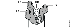
Power supply to mains switch box
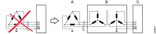
TN or TT mains are to be preferred

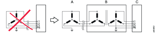
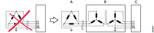
If the power supply system isn’t as shown above an isolation transformer is needed. Below are shown some examples of additional power supply system types using up to 480 VAC (phase to phase) where an isolation transformer is required
Examples
Legend | |
|---|---|
A | Factory power supply system |
B | Transformer |
C | Mains switch box |
Examples 1:

Examples 2:
Examples 3:

Examples 4:
Examples 5:
Placement of FlexSystem
The FlexCarrier should be mounted vertically for optimal system functionality. This will allow for best air flow and heat transfer.
The FlexSystem and the mains switch box can be mounted in any normal industrial environment without any extra enclosure, if local regulations do not require otherwise.
The FlexSystem should not be exposed to excessive amount of vibrations. The vibration should be less than 10 g (98 m/s2) and between 1000 to 2000 Hz.
In this Section
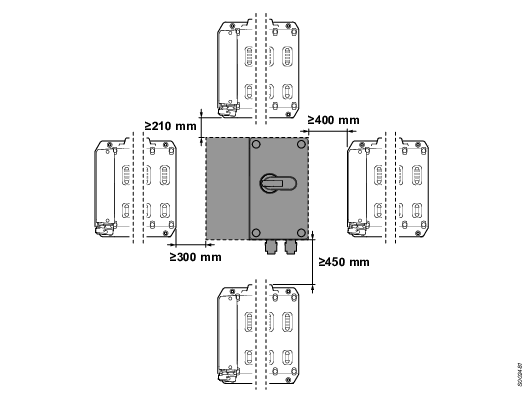
Distances between FlexSystem parts
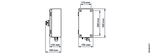
Placement of fastening holes
When fastening the units, use:
Screw: M6
Torque: 9.8 Nm
FlexCarrier

FlexMSB 60

FlexMSB 30
Mount the mains switch box in a convenient place where it is easily accessible. It shall be possible to open the mains switch box in order to get access to the fuses.
Distance from thermal insulating wall

The FlexSystem must be placed 20 mm from a thermal insulating wall.
Daisy chain
It is possible to connect one FlexCarrier to other FlexCarriers in a daisy chain. Then it is possible for one FlexController to control more FlexDrives than fits in one FlexCarrier.
FlexCarrier address setting
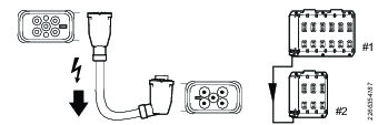
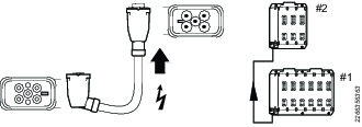
Set the addresses in sequential order. The first FlexCarrier has address set to 1, set the second to 2, the third to 3 etc.
The default factory setting is 0. It is not allowed to have 0 as an address in an installed application.

First FlexCarrier with address 1
Second FlexCarrier with address 2
Third FlexCarrier with address 3
Placement of modules in FlexCarrier
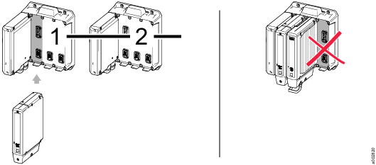

The following rules apply to the placement of modules in a FlexCarrier:
The FlexController must be placed in the first device slot on the first FlexCarrier in a daisy chain.
Every device slot must contain a module (FlexController, FlexDrive or a FlexDrive blank module).
Emergency stop for FlexSystem
The FlexSystem makes it possible to connect emergency stops (e-stops) in different configurations with up to 15 FlexCarriers.
For the e-stop button and reset button there is a protected 24VDC input via the e-stop terminals on the front of the first FlexCarrier in the system.
Test the e-stop function every time the power supply chain is changed, to make sure the e-stop function is still intact.
In this Section
E-stop rules
The e-stop works according to the rules below:
The first FlexCarrier controls the e-stop functions.
The first FlexCarrier must have address 1.
Place the FlexController in the first FlexCarrier.
An e-stop configuration plug must be inserted in each FlexCarrier. If not, the e-stop will not work.
The first FlexCarrier must have either an entry plug or an ASM plug.
If an e-stop entry plug is placed in another FlexCarrier than the first one the e-stop will not work.
If a control cable is missing in between FlexCarriers, the next FlexCarrier will not start.
If the control cables have swapped positions, parts of the system will not be started.
Do not connect any daisy chained FlexCarriers to the controller input inter-com port on the first FlexCarrier.
In ASM mode the e-stop and reset buttons are only sensed and the safety PLC is controlling the system.
FlexCarriers in the daisy chain with higher address than 1 may be connected in any order.
E-stop configuration plug
The following plugs are available:
-
E-stop entry plug
-
Bypass plug
-
Advanced Security Module (ASM) plug.
E-stop entry plug
The e-stop entry plug is used in the first FlexCarrier in an e-stop chain. It has four connectors for the e-stop button and power feed and two connectors for the reset button.

Terminal | Function |
|---|---|
6 | +24V |
5 | E-stop + |
4 | E-stop - |
3 | GND |
2 | E-stop reset + |
1 | E-stop reset - |
Bypass plug
The bypass plug is used in the second FlexCarrier and each of the following FlexCarriers in an e-stop chain. The bypass plug does not have any connections and the plug covers the 24VDC in.
ASM plug
If an external safety PLC will control the e-stop, use an ASM plug in the first FlexCarrier in the e-stop chain.
Emergency stop modes
The e-stop can be configured in different modes:
-
E-stop source from button connected to the first FlexCarrier
-
E-stop source safety PLC connected to FlexController.
E-stop source from button connected to first FlexCarrier
In this mode the first FlexCarrier in the daisy chain is used as a primary FlexCarrier. Connect an e-stop entry plug in the first FlexCarrier. If more FlexCarriers are connected in a daisy chain, connect a bypass plug in each of the following FlexCarriers. The bypass plug is used to signal that the chain is correct.
All FlexCarrier must have a plug otherwise the e-stop function will prevent the FlexSystem to start
For the system to work, an e-stop and a reset button needs to be connected to the entry plug.
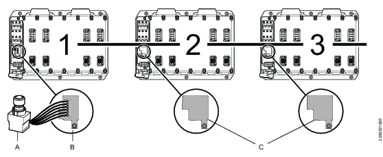
-
First FlexCarrier with e-stop entry plug
-
Second FlexCarrier with bypass plug
-
Third FlexCarrier with bypass plug
E-stop source safety PLC connected FlexController
In this mode an external safety PLC controls the e-stop. The safety PLC is connected to a PROFINET fieldbus module on the FlexController. Use an ASM plug on the FlexCarrier.
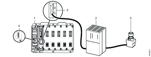
Pos | |
1 | First FlexCarrier |
2 | Safety PLC |
3 | E-stop |
4 | ASM plug |
5 | PROFINET fieldbus |
Error-Bits reported by the FlexController via PROFIsafe shall not be used to trigger the safety function of a device or system.
GSD-file
Atlas Copco delivers a GSD-file that includes a description of the FlexSystem as an IO device in PROFINET. Use this GSD-file when configuring the PROFINET system.
Logical ports of PROFISafe module
Logical port | Description |
DO1 | Digital Output 1 |
DO2 | Digital Output 2 |
TO1 | Test Output 1. ProfiSafe module to external sensors. |
TO2 | Test Output 2. ProfiSafe module to external sensors. |
DI1 | Digital Input 1 |
DI2 | Digital Input 2 |
DI3 | Digital Input 3 |
DI4 | Digital Input 4 |
DI5 | Digital Input 5 |
DI6 | Digital Input 6 |
Logical illustration - PROFISafe implementation in the FlexSystem

Input process image
The input process image contains the data and status collected from the local digital inputs of the PROFISafe module as well as the PROFIsafe frame elements which are to be transported via PROFINET from the PROFISafe module to the PROFIsafe PLC.
Bit 0 | Bit 1 | Bit 2 | Bit 3 | Bit 4 | Bit 5 | Bit 6 | Bit 7 | |
Byte 0 | DI_1 | DI_2 | DI_3 | DI_4 | DI_5 | DI_6 | Res | Res |
Byte 1 | QDI_1 | QDI_2 | QDI_3 | QDI_4 | QDI_5 | QDI_6 | Res | Res |
Byte 2 | Res | Res | Res | Res | Res | Res | Res | Res |
Byte 3 | PROFIsafe Control Byte | |||||||
Byte 4 | PROFIsafe CRC2 | |||||||
Byte 5 | ||||||||
Byte 6 | ||||||||
The qualifier bits QDI_X indicate whether a fail-safe error was detected at the corresponding input or output channel of the ProfiSafe module. If set to 0, the input or output state is “fail-safe”, that is, the input data contains the fail-safe values or the output is locally set to the fail-safe value by the ProfiSafe module. A qualifier with the value 1 indicates that the input or output is operated without any fail-safe errors.
The input- and output channel qualifiers are operated individually, that is, the qualifiers show the error state only for the corresponding channel or channel group. Other channels may still operate correctly.
Bit | Value | Description |
DI_x | 0 | Input channel inactive (safe state) |
1 | Input channel active | |
QDI_x | 0 | Input channel status “error”, DI_x set to inactive / safe state |
1 | Input channel normal operation. DI_x reflects physical input value | |
QDO_x | 0 | Output channel status “error”. DO_x is set to safe state / inactive |
1 | Output channel normal operation. DO_x can be set/reset via safety fieldbus protocol |
Output process image
The output process image of the PROFISafe module contains all the safety-relevant data sent from the F-Host to the PROFISafe module. The data of the output process image is used on the one hand to control the safe digital output states of the PROFISafe module and on the other hand to send the fail-safe error acknowledge data for the digital inputs and outputs of the PROFISafe module.
Bit 0 | Bit 1 | Bit 2 | Bit 3 | Bit 4 | Bit 5 | Bit 6 | Bit 7 | |
Byte 0 | DO_1 | DO_2 | Res | Res | Res | Res | Res | Res |
Byte 1 | ERDI_1 | ERDI_2 | ERDI_3 | ERDI_4 | ERDI_5 | ERDI_6 | Res | Res |
Byte 2 | ERDO_1 | ERDO_2 | Res | Res | Res | Res | Res | Res |
Byte 3 | PROFIsafe Control Byte | |||||||
Byte 4 | PROFIsafe CRC2 | |||||||
Byte 5 | ||||||||
Byte 6 | ||||||||
Configuration | Dual-Channel | Single-Channel |
DO_1 | Requested value for dual channel output group | Requested value for DO1. |
DO_2 | Unused / Ignored | Requested value for DO2. |
ERDI_1, ERDI_3, ERDI_5 | Error-Reset Bits of the dual channel inputs | Error-Reset Bits of the inputs DI1, DI3, DI5, DI7. |
ERDI_2, ERDI_4, ERDI_6 | Unused / Ignored | Error-Reset Bits of the inputs DI1, DI3, DI5, DI7. |
ERDO_1 | Error-Reset Bits of the dual channel inputs | Error-Reset Bits of the output DO1. |
ERDO_2 | Unused / Ignored | Error-Reset Bits of the output DO2. |
Bit | Value | Description |
DO_x | 0 | Output channel inactive (safe state, low). |
1 | Output channel active (high). | |
ERDI_x | 0 | Input channel error reset not requested. |
1 | Input channel error reset requested. | |
ERDO_x | 0 | Output channel error reset not requested. |
1 | Output channel error reset requested. |
E-stop cable length
The maximum allowed resistance for the e-stop chain is 200Ω. To calculate the maximum allowed cable length the following formula should be used:
2,7Ncarriers + 0,22L10-cabletotL + REstop cable per m • LEstop cable • 6 ≤ 200Ω
NCarriers = Number of FlexCarriers
LIO-cabletot =Total length of control cable
REstop cable per m = Resistance per meter of e-stop cable
LEstop cable = Length of e-stop cable
Maximum and minimum wire size
AWG: 16, 18, 20, 22, 24, 26, 28
mm2: 0,2 - 1
Example:
A 14 channel system with two 6 slot and one 3 slot FlexCarriers. The system has got a normal e-stop solution with three e-stop buttons and one restart button. The e-stop cable length is 150 m and the control cables are 2 m and 5 m.
The e-stop cable is a 6 wire AWG 22 (0.64 mm2 0.11 Ω/m).
2.7·3 + 0.22(2+5) + 0.11·150·6 = 108.64 ≤ 200
For power distribution reasons the control cable length must not exceed 30 m in any segment.
Protective earth connection for FlexSystem
The FlexSystem is connected to protective earth through the power cables (the power cable and the tool cable). The power cables must be connected even if they are not powered.
Never connect two FlexCarriers without the power cable. Always use both control cable and power cable.
The FlexSystem is still connected to protective earth if the mains switch board is switched off or a fuse is blown.
Supported fieldbus module
The following fieldbus modules types are supported:
DeviceNet
EtherNet IP
Profinet IO
Profibus
CC Link
CC Link IE
EtherNet IP M40
License Introduction
Licenses for controller features are managed through the Functionality Management System (FMS). This allows customers to tailor controller functions to their specific needs through a dynamic licensing scheme.
Licenses can be obtained for individual features or collections of features and can be deployed across multiple Virtual Stations. The licenses can be returned to the pool when they are no longer required. Licenses can be obtained through the Atlas Copco License Portal (ACLP). Licenses can be downloaded from the ACLP and managed/distributed through ToolsTalk, or can be stored on a FMS Portable (USB drive) to be inserted into the controller.
Note that the creation and management of a customer account in the ACLP is not covered in this documentation. Contact your local Atlas Copco representative for more information.
Licenses Overview
Configuration of features governed by licenses can be done even in the absence of an installed license. For example configuration of tightening programs and configuration of Multistep programs. Assigning these features to a tool or virtual station is also possible. Running the feature without a valid license, however, will require the installation of the appropriate license.
License enforcement is performed at two stages: assignment and runtime (trigger pressed). If a feature for which no license is installed is assigned to a Virtual Station, a red exclamation mark will appear at the Virtual Station View in ToolsTalk 2. The controller GUI will also show a warning triangle at the tool or task section (depending on what is missing). If a feature for which no license is installed is started (i.e. trigger pressed), an event will be presented to the user informing the user of which license is missing. It will not be possible to proceed without a correct license installed.
Running an unlicensed feature will, in most cases, result in a locked tool.
Many features and functions in the controller require a license in order to be assigned and used by a virtual station. There are four types of licenses:
Virtual Station Type
Fixed collection of features bundled together in a single package. The Virtual Station Type determines, among other things, what tools can be run, how many programs and sequences can be used, which tightening strategies are available, and the type of reporting that can be done. The features contained in each Virtual Station Type are features that often are used in conjunction with each other, or which have internal dependencies that require the presence of other features in the package. Virtual Station Types are assigned in their entirety to a virtual station. The virtual station can then make use of all features contained in the Virtual Station Type. In order to be able to perform tightenings, a Virtual Station has to be assigned a Virtual Station Type license. Depending on the license type, various tightening options will be enabled or blocked.
Sync Functionality Type
Works in the same way as described in Virtual Station Type but used for fixtured systems. To be able to run several tools on a virtual station each tool need a sync functionality license.
Virtual Station Feature
Individual features which can complement Virtual Station Types. A lot of features can be purchased as a single license.
Controller Feature
Features that are controller-wide. These are features which are assigned to a controller and once assigned can be used by all virtual stations on that controller.
License Sources
Licenses used on a controller can be pulled from several different sources. The number of simultaneous sources is limited to 10 (either 10 FMS Portable sources, or one License Server (TT2) in addition to 9 FMS Portable sources). If you would like to add licenses from a source when the source limit (10) has been reached, all licenses from one source need to be removed from the controller to make room for licenses from the other source.
Source Overview
The Source Overview tab (License assignment > Source Overview) provides the user with an overview of the licenses installed on the controller, as well as where they were installed from. A maximum number of 10 different sources can be displayed here, and each will be designated with FMS P (for FMS Portable, or dongle), or License Server (TT2).
Clicking on any license source will present that source's detailed license source information. It lists the source name and type, as well as the number and type of licenses in each category (Virtual Station Type, Virtual Station Feature and Controller Feature).
Installation and Upgrade
In this section, you can find information to help with the initial installation of the product, or upgrading from one version to another.
Installation overview
FlexSystem components
The FlexSystem must consist of the following parts:
A | FlexCarrier |
B | FlexController |
C | FlexDrive |
D | FlexIAM (Flex Intelligent Application Module) |
E | Tools |
F | FlexSystem cables |
The FlexSystem can also include of the following parts:
G | FlexDrive blank (required if there is an empty slot in the FlexCarrier) |
H | FlexFan module |
Hardware installation
Preparations
Make sure that every external connector point on the FlexSystem is mated with either a cable connector or a protection plug.
Tools
Needed tool | Task |
|---|---|
Torx T25, blade length minimum 200 mm (5.7 Nm). Socket for torque wrench or bits for torque screwdriver | Mounting FlexDrive |
Torx T20 (0.8 Nm) | Mounting FlexFan |
Torx T20 (0.8 Nm) | Fastening Lid for FlexController and FlexCarrier |
Slotted screw M2.5 | Settings for hex-switch and cable terminal for emergency stop |
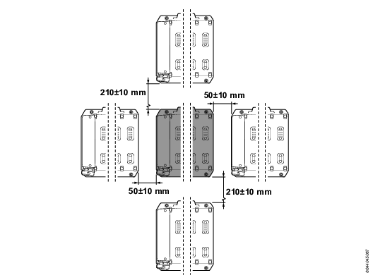
Mounting FlexSystem
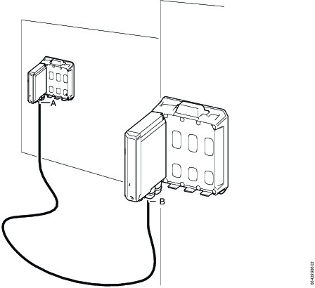
For minimal footprint select power cables and mount the FlexSystem according to the specified distances.
The FlexCarrier should be mounted vertically for optimal system functionality. This will allow for best air flow and heat transfer. Mounting FlexCarrier horizontally can affect the lifetime of the system.
The FlexSystem and the main switch box can be mounted in any normal industrial environment without any extra enclosure, if local regulations do not require otherwise.
The FlexSystem should not be exposed to excessive amount of vibrations. The vibration should be less than 10 g (98 m/s2) and between 1000 to 2000 Hz.
Screw: M6, Torque: 9.8 Nm
Distances between FlexSystem parts for minimal footprint (with FlexFan)
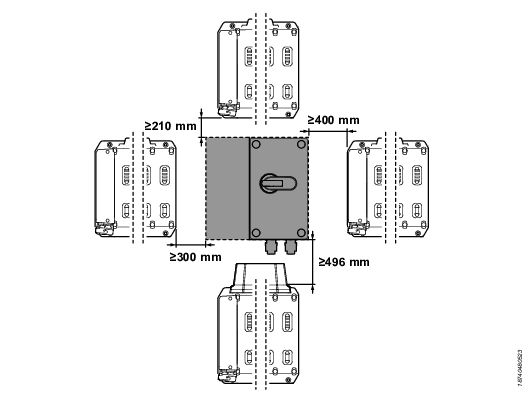
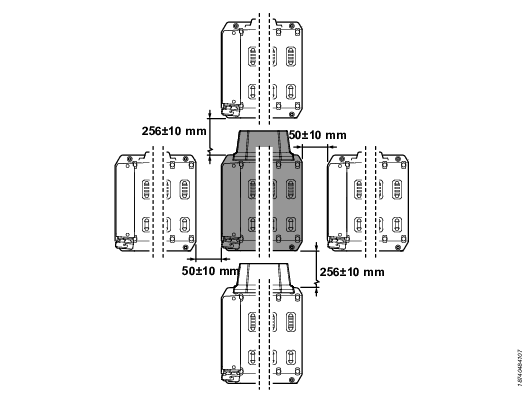
Distances between FlexSystem parts for minimal footprint (without FlexFan)
In this Section
Placement of FlexSystem
Placement of fastening holes
Distance from thermal insulating wall
The FlexSystem must be placed at least 20 mm from a thermal insulating wall.
Cable planning
Recommended cables for minimum footprint
For information of dimensions for minimal footprint installation, see Mounting FlexSystem.
Power cables
To connect a FlexCarrier to mains switch board, use the power cable:
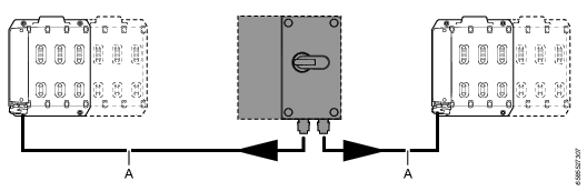
Name | Article number | |
|---|---|---|
A | DaisyCh Power Cable SE 1m | 4222 1948 01 |
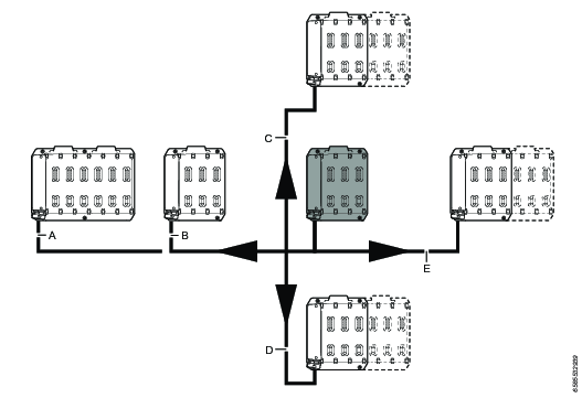
To connect a FlexCarrier to a 3 slot FlexCarrier, use these power cables:
To connect a FlexCarrier to a 6 slot FlexCarrier, use these power cables:
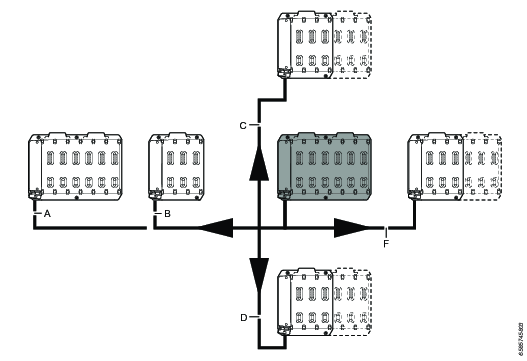
Name | Article number | |
|---|---|---|
A | DaisyCh Power Cable LE 0.365m | 4222 2082 12 |
B | DaisyCh Power Cable LE 0.22m | 4222 2082 11 |
C | DaisyCh Power Cable RES 0.65m | 4222 2084 11 |
D | DaisyCh Power Cable SRE 0.65m | 4222 2083 11 |
E | DaisyCh Power Cable RE 0.22m | 4222 1946 11 |
F | DaisyCh Power Cable RE 0.365m | 4222 1946 12 |
Control cables
Use these control cables:
System orientation | Name | Article number |
|---|---|---|
Horizontal 3 slot | Daisy Control Cable 0.44m | 4222 2062 01 |
Horizontal 6 slot | Flex Daisy Control Cable 0.61m | 4222 2062 04 |
Vertical system | Flex Daisy Control Cable 0.84m | 4222 2062 03 |
Recommended cables for general positioning
FlexCarriers can be positioned freely, with more spacing or with FlexCarriers not placed in the same plane.
Power cables
The selection is based on the routed length between cable ends from A to B. Select a FlexPower cable with the closest longer length to the measurement.
The minimum bending radius (0.12 m) must be followed.
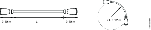
Length (L) | Name | Article number | Remark |
|---|---|---|---|
1 m | Power Cable | 4222 1948 01 | DaisyCh Power Cable SE 1m |
2 m | Power Cable | 4222 1948 02 | DaisyCh Power Cable SE 2m |
3 m | Power Cable | 4222 1948 03 | DaisyCh Power Cable SE 3m |
5 m | Power Cable | 4222 1948 05 | DaisyCh Power Cable SE 5m |
10 m | Power Cable | 4222 1948 10 | DaisyCh Power Cable SE 10m |
Control cables
The selection is based on the routed length between cable ends from A to B. Select a FlexControl cable with the closest longer length to the measurement.
The minimum bending radius (0.1 m) must be followed.
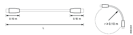
Length (L) | Name | Article number | Remark |
|---|---|---|---|
1 m | Control Cable | 4222 2062 11 | Flex Daisy Control Cable 1m |
2 m | Control Cable | 4222 2062 12 | Flex Daisy Control Cable 2m |
3 m | Control Cable | 4222 2062 13 | Flex Daisy Control Cable 3m |
5 m | Control Cable | 4222 2062 15 | Flex Daisy Control Cable 5m |
10 m | Control Cable | 4222 2062 20 | Flex Daisy Control Cable 10m |
Installation instructions
Install the FlexSystem in the following order:
Install the first FlexCarrier.
Install daisy chained FlexCarriers.
Install the FlexController.
Install the FlexDrives and FlexBlank modules.
Tighten the modules to the FlexCarrier.
Connect the tools.
Mount the FlexFan module (optional).
Route and install power and control cables to FlexCarrier.
Turn on the FlexSystem.
Test the e-stop function.
Configure the system.
Each step is explained in detail in the following section.
Install first FlexCarrier
Make sure the circuit breakers are off (down).
Fasten the FlexCarrier. Use M6 screws. Tighten at 9.8 Nm.
Use 4 screws for a 3 slot FlexCarrier.
Use 6 screws for a 6 slot FlexCarrier.
Set the FlexCarrier address.
The first FlexCarrier must be set to 1, the second to 2 etc. The default factory setting is 0. It is not allowed to have 0 as an address in an installed application. For more information on system planning, see FlexSystem System Overview Manual.
Select e-stop plug:
E-stop entry plug.
Advanced Security Module (ASM) plug.
Fasten the e-stop cables to the e-stop entry plug according to schematics. This step is not applicable for the ASM plug.
This is most easily done on a working bench.
Plug in the e-stop plug.
If the 24 VDC OUT and 24 VDC IN will be used, prepare the connectors.
This is most easily done on a working bench.
Install the 24 VDC IN/OUT connectors. Make sure you use the correct connector.
Do not connect the cables to the connector when the connector is fastened to the FlexCarrier.

If using an external 8 A power supply it shall be current limited to 8 A, double insulation. It shall be certified according to EN 61010-1 or according to another standard compatible with the requirements in EN 61010-1 (for example EN 60950 or EN 60601).
Route the cables through the gasket.
Make sure the cables are not pinched or damaged when the cover is put back on.
Do not route the cables so they block the LED light guide in the cover.
Install daisy chained FlexCarriers
Make sure the circuit breakers are off (down).
Mark where to fasten the FlexCarrier. See dimensional drawings for measurements.
Fasten the FlexCarrier.
Set the FlexCarrier address.
Set the addresses in sequential order. If the first FlexCarrier has address set to 1, set the second to 2, the third to 3 etc.
The default factory setting is 0. It is not allowed to have 0 as an address in an installed application. For more information on system planning, see FlexSystem System Overview Manual.
Two FlexCarriers connected in a FlexSystem cannot have the same address.
Install the bypass plug.
If the 24 VDC OUT will be used, prepare the connector.
This is most easily done on a working bench.
Install the 24 VDC OUT connector.
Do not connect the cables to the connector when the connector is fastened to the FlexCarrier.

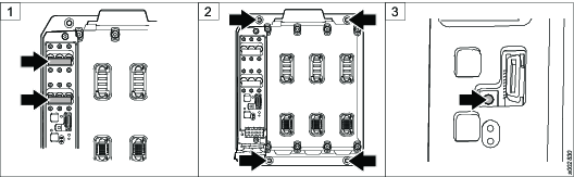
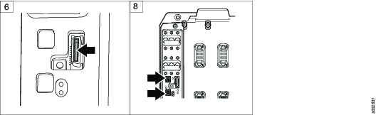
Install FlexController
Insert the FlexIAM.
Plug in the FlexController in the first slot on the FlexCarrier.
Fasten the FlexController to the FlexCarrier. Wait to tighten it until all modules are fastened to the FlexCarrier.
Route the cables to the FlexController.
Prepare the gasket for cable routing.
Install the cables.
Make sure that the cable will fit under the cover.
Max length from connection panel surface to inside of cover (L).
max 45.7 mm
Max cable bend (R)
25 mm
Route the installed cables down through the cable routing gasket.
To prevent dust or water to get inside the FlexController make sure it is a tight fit between the cable and gasket.
Fasten the cover. Make sure the cover fits tight.

Install FlexDrive
Plug in the FlexDrive in a slot on the FlexCarrier.
Fasten the FlexDrive to the FlexCarrier with the screws. Wait to tighten it until all modules are fastened to the FlexCarrier.
Install FlexBlank
Each slot on the FlexCarrier must be filled. If there is no need of a FlexDrive in the last FlexCarrier in a daisy chain, add a FlexBlank module to the device slot.
Plug in the FlexBlank module in a slot on the FlexCarrier.
Fasten the FlexBlank module to the FlexCarrier with the screws. Wait to tighten it until all modules are fastened to the FlexCarrier.
Tighten module to FlexCarrier
Use torque 5.7 Nm. Screw head TX25.
For each module in the FlexCarrier:
Tighten top left screw.
Tighten bottom left screw.
Tighten top right screw.
Tighten bottom right screw.
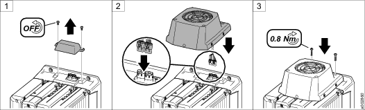
Mount FlexFan
Power must be turned off when mounting a FlexFan.
This step is optional.
For 3 slot FlexCarrier:
Remove the fan cover on the FlexCarrier.
Plug in the FlexFan cables to the contacts on the FlexCarrier.
Fasten the FlexFan with the screws closest to the backside. Use torque 2.2 Nm.
Screw MRT M4x20 tuflok (or thread-locking adhesive) plus a washer.
Fasten the FlexFan with the remaining screws closest to the front. Torque 2.2 Nm.
Screw MRT M4x70 tuflok (or thread-locking adhesive).
For 6-slot FlexCarrier, repeat for second FlexFan.

Route and install power- and control cables to FlexCarrier
Make sure that the cables are in good condition before connecting them to the system. Check that
Cables are not damaged
Connectors are not damaged.
If these conditions are not fulfilled the system must not be connected to mains or switched on.
Systems where damages to connections or cables are found must be disconnected and repaired immediately.
Procedure
Install power cables.
Install control cables.
Install tool
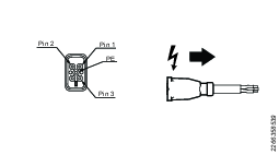
Connect the tool to the tool cable.
To avoid damaging connection pins. Line up the plug to the socket and ensure that the plug is parallel before insertion.

Plug in the tool cable.
Turn on the system
When turning on the system the power residual current device may switch off the power.
Before you power up the system make sure it is installed the same way as it was planned and configured. Otherwise it will not work.
On the FlexCarriers, switch the circuit breakers on (up).
Fasten the FlexCarrier cover. Use torque 2.2 Nm.
Make sure the cables are not pinched or damaged when the cover is put back on.
Do not draw the cables in the way of the LED light guide in the cover.
Turn the handle on the mains switch box. This will turn the system on.
The FlexSystem is now potentially dangerous since the e-stop functionality is not tested yet.
Test e-stop function
See Test and validate installation.
Test the e-stop function every time the power supply chain is changed, to make sure the e-stop function is still intact.
Wait at least 30 seconds between power off and power on when you restart the FlexSystem.
Software installation
Configure the system
The FlexSystem is configured with ToolsTalk 2 and with the web graphical user interface (web GUI).
Connect to the web GUI, refer to Configuration > Getting started.
Configure the FlexSystem according to ToolsTalk 2user guide.
Installing Licenses on the Controller
Note that licenses sources are limited to 1 License Server (TT2) and 9 FMS Portables (dongles) simultaneously. Licenses are installed either through the server (ToolsTalk 2) or FMS Portable. If the license source limit is reached, all licenses from one source need to be removed from the controller in order to add licenses from another source.
Before installing licenses through the server (ToolsTalk 2), make sure that the controller time is synced with the server time.
Installing from the Server
Distributing server-based licenses is done through ToolsTalk 2. Please refer to the ToolsTalk 2 User Guide for instructions on installing licenses.
In order to be able to install licenses using ToolsTalk 2, the correct license server needs to be configured:
Select the Settings menu, and select the Server connections tab.
In the Atlas Copco License Manager field, set the switch to On.
Insert the correct Server host IP address (usually the same as the IP address for ToolsTalk 2) and Server Port.
Select Apply.
Installing from FMS Portable (USB)
The Functionality Management System (FMS) uses a special FMS Portable device to transfer functionality to and from a controller. The USB flash drive contains both a general purpose memory area and a trusted storage area that is only accessible by the License manager in a controller. The purchased feature items are downloaded from Atlas Copco to the general purpose area. The first time the FMS Portable is inserted into a controller with a License manager, the file is detected and decoded and the feature items are transferred to the trusted storage area that is only accessible from a License manager.
If you have a USB drive with the licenses installed, perform the following steps to install them on the controller.
Insert the USB into the USB port in the controller
The USB License Management window will pop up in the GUI. The Pool column will show the total license count on the controller from all sources. The Available on FMS P column shows the licenses available on this dongle, while the From this FMS P column shows the number of licenses that have been moved to this controller from this particular FMS P.
Select the left-pointing arrow next to license you want to install on the controller.
The number in the Available on FMS P column will decrease by 1 and the number in the From this FMS P column will increase by 1.
The user will be presented with events on the controller for both license transfer start and end.
License sync
Existing licenses are checked against the license server every two hours. If no response from the license server is obtained within a 14 day period, the affected licenses will be revoked. The user will also be warned when licenses are about to expire. When a license is within 7 days of expiration, the user will be presented with a warning once every two hours. If licenses are not renewed, they will expire and the affected functions will no longer be available.
Relevant Information
Removing Licenses from the Controller
One way of removing an FMS Portable-installed licenses are described, for instructions how to remove server-installed licenses, please refer to the ToolsTalk 2 User Guide.
Removing FMS Portable-Installed Licenses
Make sure the FMS Portable is inserted into the USB port in the controller.
[If the USB License Manager window is not visible] Select the License Assignment menu.
Select the USB icon in the top right of the window.
The USB License Manager window pops up.
Select the right-pointing arrow next to the license you want to remove from the controller.
Licenses that are assigned to virtual stations can be removed from the controller. However, the Virtual Station will become unusable as a result.
Test and validate installation
Test and validate installation
Verify that the FlexSystem is possible to stop in a safe way, and that a loss of a safety function will put the FlexSystem in a safe state
Wait at least 30 seconds between power off and power on when you restart the FlexSystem.
Test and validation of PROFISafe controlled e-stop
Example
This is a PROFISafe controlled FlexSystem with two FlexCarriers. In this configuration there is one e-stop button and one reset button attached to the safety PLC.

Pos | |
|---|---|
A | E-stop. Stop input and reset input |
B | Safety PLC. |
C | PROFINET connection. |
D | First FlexCarrier with FlexController. This FlexCarrier has an ASM plug. |
E | Daisy chained FlexCarrier. This FlexCarrier has a bypass plug. |
F | FlexControl cable. |
The e-stop button, the reset button and the safety PLC are not considered to be a part of the FlexSystem. These sources must be verified by the machine tool builder (MTB).
Prerequisites for test and validation of PROFISafe
Make sure that all equipment is in place. Pay special attention to the following:
The first FlexCarrier has an ASM plug connected.
The daisy chained FlexCarriers have a bypass plug connected.
That a PROFINET cable is connected between the FlexController and the safety PLC.
All FlexCarriers are fully populated, no empty slots are allowed. If there is an empty slot, equip it with a FlexBlank module.
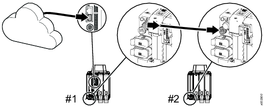
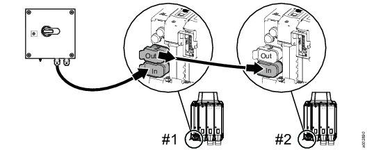
Connect all FlexCarriers together with FlexControl cables, pay attention to the IN and OUT markings on the FlexCarriers.
The first and the last FlexCarrier in the daisy chain must only have one FlexControl cable connected.
That you have access to the FlexSystem web GUI, Reports > Events > View all events. All alarms are shown in the Events list.
PROFINET IO Controller with PROFIsafe (Safety PLC) must be parameterized with configuration parameters as shown in table. PROFIsafe destination addresses must be unique within the station and the network.
Safety PLC must be programmed to activate safe output DO1 (bit 0) and monitor feedback of digital input DI4 (bit 3).
Power on
Power on the FlexSystem and wait for the FlexSystem to come online, verify that:
-
No tightening can be made.
-
An alarm stating that the FlexSystem is stopped.
Reset of stop condition
Reset the stop condition and verify that:
-
The alarm regarding the stop is removed and that it is possible to perform a tightening.
The FlexSystem is now potentially dangerous since the stop functionality is not tested yet.
Test e-stop sources
Trigger all possible stop safety PLC input sources individually, for example, e-stop buttons. Verify that:
-
An alarm stating that the FlexSystem is stopped is triggered.
Between every stop a reset has to be made.
Test loss of PROFINET cable
-
Disconnect the PROFINET cable and verify that:
-
An alarm stating that the FlexSystem is stopped is triggered.
-
-
2. Reconnect the cable and verify that:
-
The FlexSystem remains stopped until reset has been made.
-
Test loss of FlexCarrier e-stop plug
-
Trigger a stop condition and verify that:
-
An alarm stating that the FlexSystem is stopped is triggered.
-
-
Disconnect one or more FlexCarrier’s e-stop plug and verify that:
-
A reset action is not possible, that is, the FlexSystem remains stopped regardless of reset activity.
-
-
3. Reconnect the e-stop plug and verify that:
-
The FlexSystem remains stopped until reset is activated.
-
Stop functionality test during tightening
Start a tightening and trigger one e-stop source, for example, an e-stop button. Verify that:
The tightening is stopped.
The tightening does not continue when the stop condition is removed. An automatic restart can be made if it can be implemented in a way that guaranties that no injury can occur.
The tightening is not restarting if reset is pressed and stop condition remains.
A new tightening is possible when stop condition is removed and reset function is activated.
Check configuration parameters
The configuration parameters for the safety module are included in the GSD-file provided by Atlas Copco. The parameters shall not be altered.
Check that the parameters are correct by verifying that the checksum is:
-
0x4DC13CF8.
Configuration parameters
Parameter | Atlas Copco FlexSystem |
|---|---|
CH1/2: Input Enabled | Disable |
CH1/2: Input Channel Mode | Single Channel |
CH1/2: Input Type | DIC |
CH1/2: Input Reset Type | Manual |
CH1/2: Input Test Output Signal | 2400us |
CH1/2: Input Debounce Filter Time (400us steps) | 0 |
CH1/2: Input Consistency Filter Time (400us steps) | 0 |
CH3/4: Input Enabled | Enable |
CH3/4: Input Channel Mode | Single Channel |
CH3/4: Input Type | DIC |
CH3/4: Input Reset Type | Manual |
CH3/4: Input Test Output Signal | 2400us |
CH3/4: Input Debounce Filter Time (400us steps) | 125 |
CH3/4: Input Consistency Filter Time (400us steps) | 625 |
CH5/6: Input Enabled | Disable |
CH5/6: Input Channel Mode | Single Channel |
CH5/6: Input Type | DIC |
CH5/6: Input Reset Type | Manual |
CH5/6: Input Test Output Signal | 2400us |
CH5/6: Input Debounce Filter Time (400us steps) | 0 |
CH5/6: Input Consistency Filter Time (400us steps) | 0 |
CH1/2: Output Enabled | Enable |
CH1/2: Output Channel Mode | Dual Channel |
CH1/2: Output Reset Type | Manual |
CH1/2: Output Test Offset (extension) | No Offset |
iPar CRC | 0x4DC13CF8 |
Test and validate entry plug controlled e-stop
Example
This is a FlexSystem using e-stop entry plug to control the e-stop, a discrete e-stop solution. The stop input source can be buttons, light curtains or other sensors, however they need to be able to break two signal paths in a safe manner. One or more stop sources can be connected in series.
Pos | |
|---|---|
A | E-stop. Stop input and reset input. |
B | Entry plug installed on the first FlexCarrier. |
C | Bypass plugs installed on the daisy chained FlexCarriers. |
Prerequisites for test and validation of FlexSystem
Make sure that all equipment is in place. Pay special attention to the following:
The first FlexCarrier have an e-stop entry plug connected.
The daisy chained FlexCarriers have a bypass plug connected.
The e-stop button is a breaking model (N.C. Contacts) and that it is connected to the e-stop entry plug
The reset button is of a closing model (N.O. Contacts) and that it is connected to the e-stop entry plug.
Make sure that the screws on the terminal block are securely tightened, to prevent cables from disconnecting.
All FlexCarriers are fully populated, no empty slots are allowed. If there is an empty slot equip it with a FlexBlank module.
Connect all FlexCarriers together with FlexControl cables, pay attention to the IN and OUT markings on the FlexCarriers.
The first and last FlexCarrier in the daisy chain should only have one FlexControl cable connected.
That you have access to the FlexSystem web GUI, Reports > Events > View all events. All alarms are shown in the Events list.
Power on
Power on the FlexSystem and wait for the FlexSystem to come online, verify that:
-
No tightening can be made.
-
An alarm stating that the FlexSystem is stopped is triggered.
Reset of stop condition
Reset the stop condition and verify that:
-
The alarm regarding the stop is removed and that it is possible to perform a tightening.
The FlexSystem is now potentially dangerous since the stop functionality is not tested yet.
Test e-stop source
Trigger one stop condition with all possible stop sources, for example, e-stop button, and for each input observe the following:
-
An alarm stating that the FlexSystem is stopped is triggered.
Between every stop a reset has to be made.
Test loss of FlexCarrier e-stop plug
-
Trigger a stop condition and verify that:
-
An alarm stating that the FlexSystem is stopped is triggered.
-
-
Disconnect one or more FlexCarrier’s e-stop plug and verify that:
-
A reset action is not possible, that is, the FlexSystem remains stopped regardless of reset activity.
-
-
Reconnect the e-stop plugs and verify that:
-
The FlexSystem remains stopped until reset is activated.
-
Stop functionality test
Start a tightening and trigger one e-stop source, for example, an e-stop button. Verify that:
The tightening is stopped.
The tightening doesn’t continue when the stop condition is removed. (An automatic restart can be made if it can be implemented in a way that guaranties that no injury can occur.)
The tightening is not restarting if reset is pressed and stop condition remains.
A new tightening is possible when stop condition is removed and reset function is activated.
Test loss of input stop
Start a tightening and disconnect the wires to the stop input source, for example, e-stop button. Verify that:
The tightening is halted.
An alarm stating that the FlexSystem is stopped is triggered.
Software upgrade
Installation of upgrade
To update the software perform the following steps:
Open the web GUI.
Click on the FlexSystem icon.
Select Software.
In the Software update field click on the Browse button.
Locate the new software.
Click Continue.
Follow the instructions on the screen.
When the system have restarted, restart the system again using the mains switch. This is to ensure that all system configurations have been updated. Wait 30 seconds before switching the main switch to ON again.
If the software is upgraded from version 1.2.X and the tightening program has errors in conversion after restart, do the following for all the programs in the Tightening Program list:
Double click on the tightening program, the tightening program page shows.
In the Properties of the tightening program, add a dot (.) in the Description field at the end of the string (if the field is empty, add a dot anyway).
Push the changes.
Software configuration
For information on how to configure the FlexSystem, see ToolsTalk 2 Configuration Manual.
Configuration
In this section, you can find detailed information about how to create, modify, and verify product settings.
Configuration overview
Configuration alternatives
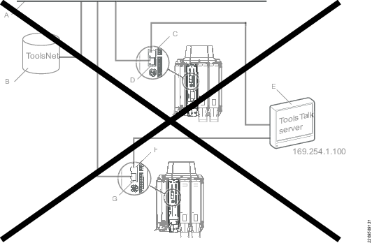
All components connected directly to factory network
In this alternative all components are connected directly to the factory network. The service ethernet port is used to connect to each separate FlexSystem.

|
Pos | |
|---|---|
|
A |
Factory network. |
|
B |
ToolsNet server. |
|
C |
ToolsTalk server. |
|
D |
Industrial PC (IPC) with a ToolsTalk client. |
|
E |
Computer connected to the factory network with a ToolsTalk client. |
|
F |
Service computer connected to the FlexSystem’s service ethernet port |
|
G |
Service ethernet port. |
|
H |
Factory ethernet port. |
|
I |
Factory ethernet port. |
Components connected via a switch to a local ToolsTalk server
In this alternative the FlexSystems are connected to a switch. The ToolsTalk server is installed on an Industrial PC (IPC) that is connected to the same switch. The service ethernet port is used to connect to each separate FlexSystem.
|
Pos | |
|---|---|
|
A |
Factory network |
|
B |
ToolsNet server |
|
C |
Switch |
|
D |
Service computer connected to the FlexSystem’s service ethernet port |
|
E |
Service ethernet port |
|
F |
Factory ethernet port |
|
G |
Industrial PC (IPC) with a ToolsTalk server and a ToolsTalk client. |
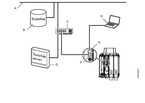
ToolsTalk server connect locally to service ethernet port
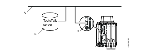
In this alternative the ToolsTalk server is installed on an IPC connected to the service ethernet port. The FlexSystem is connected to the factory network through the factory ethernet port.
|
Pos | |
|---|---|
|
A |
Factory network |
|
B |
ToolsNet server |
|
C |
Industrial PC (IPC) with a ToolsTalk server and a ToolsTalk client, connected to the FlexSystem’s service ethernet port. |
|
D |
Service ethernet port. |
|
E |
Factory ethernet port. |
More than one FlexSystem connected locally to one ToolsTalk server via service ethernet port
This alternative is not possible since the service ethernet port has a fixed IP-address.
|
POS | |
|---|---|
|
A |
Factory network |
|
B |
ToolsNet server |
|
C |
Service ethernet port. |
|
D |
Factory network |
|
E |
Industrial PC (IPC) with a ToolsTalk server, connected to the FlexSystem’s service ethernet port |
|
F |
Service ethernet port. |
|
G |
Factory ethernet port. |
Connect to web GUI
There are two ways to connect to the FlexController’s web GUI:
Through the service ethernet port (primary).
Through the factory ethernet port (secondary).
Getting started
Liability
Many events in the operating environment may affect the tightening process and shall require a validation of results. In compliance with applicable standards and/or regulations, we hereby require you to check the installed torque and rotational direction after any event that can influence the tightening result. Examples of such events include but are not limited to:
initial installation of the tooling system
change of part batch, bolt, screw batch, tool, software, configuration or environment
change of air- or electrical connections
change in line ergonomics, process, quality procedures or practices
changing of operator
any other change that influences the result of the tightening process
The check should:
Ensure that the joint conditions have not changed due to events of influence.
Be done after initial installation, maintenance or repair of the equipment.
Occur at least once per shift or at another suitable frequency.
Connecting to web GUI via service ethernet port when ToolsTalk server is connected to factory ethernet port
Make sure the DHCP settings are enabled on the computer.
When the ToolsTalk server is connected to the factory ethernet port, perform the following steps to connect to the web GUI:
-
Connect to the service ethernet port.
-
Open a web browser.
-
In the address field, type 169.254.1.1 .
The web GUI opens.
Setting up connection to ToolsTalk 2 server
|
A |
Factory network |
|
B |
ToolsTalk server |
|
C |
Factory ethernet port. |
To set the IP address for the factory ethernet port and point out the ToolsTalk server, perform the following steps:
-
Open the web GUI.
-
Click on the Settings icon.
-
Open the Network part.
-
Insert the settings for the factory ethernet port, manually or via DHCP.
-
Open the Server connections part.
-
Set the Server port and Server host obtained by ToolsTalk 2.
Relevant Information
Set PIN protection on the FlexSystem
PIN protection can be set in ToolsTalk 2 > Settings > Preferences.
PIN protection can also be set in the web GUI > Settings > PIN > Configure.
It is possible to have one or many different PIN configurations. Users can decide whether or not to activate one or several PIN configurations at the same time.
Each PIN configuration has a PIN code, a user name, a switch for enabling or disabling the user/PIN, and a list of available configurations that the user can access.
When PIN is enabled and the screen is locked, a locked padlock icon is shown at the upper-right corner of the GUI. The user can access and make changes only to the selected configuration(s) without entering any PIN code, and browse the unselected configurations with read-only access only. The unselected configurations are greyed out or disabled.
The screen lock goes automatically on after a certain time of inactivity, configurable by the user.
The minimum value of the inactivity time is 20 sec and the maximum value is 600 sec. The inactivity time is configurable and applies to all PIN configurations.
After a system startup, the controller is locked if the PIN is turned on, regardless of the current inactivity time.
The users and PIN configured apply also to the Service Port (169.254.1.1).
To enable PIN protection on the Service Port, in the PIN windows, set Use PIN for Service Port to On.
Each controller can configure up to 10 users.
The PIN of each configuration has to be unique. It is required to have at least one configuration to enable the PIN functionality on the controller.
The PIN can be configured from the Embedded controller-GUI, Web-based controller-GUI or Tools Talk 2.
Adding New Users
On the Home view, select the Settings Tab. Then, on the left, select PIN.
In the PIN window, select Configure.
Select the Plus icon at the upper-right corner of the GUI.
The PIN-Users window shows the new user. If there are not users stored in the controller, the new user is the first and only one in the list; if there are existing users stored in the controller, the new user is the last of the list.Select the new user.
The User window appears.
Enter the Name and the PIN of the new user, and then confirm the PIN.The User Name must be unique.
The Name text box can be 1 to 32 characters long.The PIN code must have 4 digits in length (numbers 1 through 9).
Enter PIN box and Confirm PIN box need to match for the changes to be applied. By default, dots are indicated in both the text box, but these are just placeholders and need to be replaced with actual PIN codes.Select Permissions. The list of the available configurations appears.
Select the check box at the left of the necessary configuration(s) the user can access and make changes.
After selecting the necessary configuration(s), select OK.
The User window appears.Select all selects all the available configurations at the same time.
Select Deselect all to clear the check boxes and undo the selection.The user can access and make changes only to the configuration(s) selected in the Permissions window, and browse the unselected configurations with read-only access. For the unselected configurations, no changes are allowed.
In the User window, select Apply.
Enabling Users
On the Home view, select the Settings Tab. Then, on the left, select PIN.
In the PIN window, select Configure.
In the PIN-Users window, select the check box at the left of the user name to be enabled.
PIN can also be enabled by clicking on the user name and setting - in the User window - the Enabled switch to On.
Activating the PIN configuration
On the Home view, select the Settings Tab. Then, on the left, select PIN.
In the PIN window, select Configure.
In the PIN-activating window, set the PIN Code switch to On.
The PIN can only be activated when at least one user/PIN is enabled. If no user/PIN is enabled, a Warning pop-up window appears.
Enter the Inactivity Timeout (in seconds), that defines the slot of time after which the screen is automatically locked up.
Default value for Inactivity Timeout is 120 seconds: this is a global setting, and cannot be set on a per user basis.
Deleting Users
On the Home view, select the Settings Tab. Then, on the left, select PIN.
In the PIN window, select Configure.
In the PIN-Users window, select the Delete icon at the right of the user name to be deleted.
If the User is removed, also the PIN is deleted. It is not possible to access any configuration through the deleted PIN.
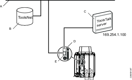
Configuring ToolsTalk 2 when ToolsTalk server is connected to service ethernet port
Open the web GUI.
Open the Settings menu and select the Server connections part.
Set the Server port and Server host, for example 4551 and 169.254.1.100 .
Connecting to web GUI via factory network when ToolsTalk server is connected to factory ethernet port
ToolsTalk 2 server must have been set up before you can connect to the web GUI.
To connect to the web GUI via the factory network, perform the following steps:
Open a web browser on a computer connected to the same factory network as the FlexSystem.
In the address field, type the IP address of the FlexSystem.
The web GUI opens.
Connecting to web GUI through the service ethernet port
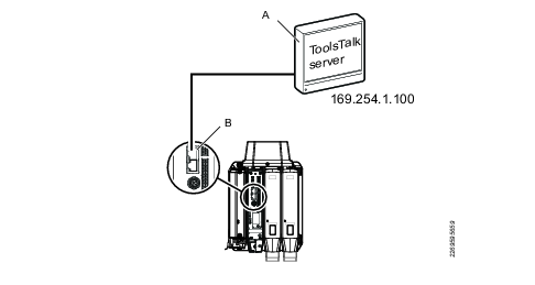
|
A |
ToolsTalk server |
|
B |
Service ethernet port. |
When the ToolsTalk server is connected to the service ethernet port, perform the following steps to connect to the web GUI:
-
Select IP address to the IPC, for example 169.254.1.100
-
Open a web browser on the IPC.
-
In the address field, type 169.254.1.1 .
The web GUI opens.
Features
Batch sequence menu

In this Section
Batch Sequence Settings
A batch sequence can consist of up to 99 batches, with a batch size of up to 250 tightenings. The batches in a batch sequence are carried out in the order listed, or by using a Socket selector to choose which batch to run.
Parameter name | Description | Default value |
|---|---|---|
Lock tool on Batch sequence compl. | A batch sequence is completed when the batch sequence counter is equal to the batch sequence size. On: The tool is locked and a tightening program or batch sequence must be selected to continue performing tightenings. Off: After completion, the batch sequence is ready to be repeated. | On |
Free order | No: The configured batches will be executed in the order listed, provided they have been configured to perform tightenings. If socket has been specified, the system will prompt for the socket when the batch is to be performed. Yes: The configured batches can be executed in any order. The operator must indicate to the system which batch is to be executed by using a Socket selector. A batch is regarded as complete when all joints have been completed. | No |
Increment on NOK | Makes it possible to increment the batch counter value even though the tightening is reported as NOK. For Max consecutive NOK to work (the maximum number of times a single bolt can be tightenened), Increment on NOK must be set to No. Setting this parameter to Yes, will allow the sequence to move on to the next tightening. | No |
Max consecutive NOK | Maximum consecutive not OK tightenings (NOK) are a defined maximum allowed number of NOK consecutive tightenings in a batch. If the Max consecutive NOK number is reached, the event Too many NOK tightenings (4020) is displayed. | 0 |
Decrement on loosening | Decrements the counter within the currently active batch. Completed batched cannot be decremented. Never: The setting is off. Counter is not decremented when loosening is performed in the active batch. Always: The batch counter is decremented when a loosening is performed. When last tightening was OK: If the preceding tightening was OK, the batch counter is decremented when a loosening is performed. | Never |
Sequence abort timer | On: The selected batch sequence can be aborted within a specified time limit Off: The selected batch sequence cannot be aborted. | Off |
Abort time (10-600) | The number of seconds during which the selected batch sequence can be aborted. | 10 |
Sources menu

Controller features, such as the Low Reaction Tightening Strategies and controller-wide functions among others, require licenses distributed through the Functionality Management System (FMS). Whereas configuration of features is possible without specific licenses, the assignment and use of those features will require the correct license to be installed on the controller. Please refer to Licenses (FMS) for more detailed information on licenses.
External signals used as tasks for tightenings are configured in the Sources menu. Sources are accessories or similar connected to a virtual station. Two types of source tasks are available:
Tightening
Batch sequence
Tightening is used to select a single tightening program.
Batch sequence is used to select a batch sequence, a series of tightening programs.
For more information about selection of tasks, see Assigning a Task to a Virtual Station.
Tool menu

Tool information
The Tool information view contains information used for giving service personnel accurate information about the tool connected to the controller, so that they can give adequate help and support, or for operators to see what tool is connected to the controller.
Parameter | Description |
|---|---|
Model | Tool model denomination. |
Max speed | The maximum rotation speed of the tool. |
Gear ratio | The ratio of the angular velocity of the input gear to the angular velocity of the output gear. |
Serial number | The tool’s serial number may be needed when the correct version of the product instruction is required, in order to get the correct spare parts or service instructions. |
Max torque | The maximum torque the tool can use for a tightening. |
Software version | Tool software version. |
Product number | The tool’s product or ordering number. |
Connection
The Connection pane displays what FlexDrive the tool is connected to.
Health
Parameter | Description |
|---|---|
Tool electronics temperature | Displays electronics temperature. Click to display a list of electronics peak temperature. |
Tool motor temperature | Displays motor temperature. Click to display a list of tool motor peak temperature. |
Maintenance
The tool stores a service interval number and counts how many tightenings can be performed before a tool maintenance or service should be performed.
Parameter | Description |
|---|---|
Last service | Date and time when last service was performed. The Last service date is set at the repair workshop. The Last service date is set to current date and time when the Reset service count button is pressed. |
Total tightenings at service | Total number of tightenings performed by the tool since it was used for the first time. This value is updated at each service, and will remain the same until the next service. |
Remaining tightenings | Total number of tightenings left until the service interval is reached. |
Service interval | Number of tightenings to be performed before the next service. Can be set in multiples of 10 000. |
Reset service counter | Reset of the Remaining tightenings counter and sets Last service date to current date. |
Calibration
Parameter | Description |
|---|---|
Last calibrated | Shows the last time the tool was calibrated. |
Calibration value | Calibration value |
Next calibration date | Set date for next calibration. |
Preparing the calibration
Make sure the tool and controller are set up to perform tightening. Set up the tool with a torque reference transducer such as an STanalyser, ACTA or BLM Bench. Refer to the torque reference transducer’s product information for set-up instructions.
Choose a tightening program with a target torque corresponding to a tightening normally used with your tool.
Calibrating the tool
To set the tool’s calibration value, it must first be calculated from the torque readings from the controller and the torque reference transducer by using the equation below.

In the Tool menu, select the tool to calibrate and go to Calibration.
Note the old calibration value in the Calibration value text box.
Make at least three tightenings and use the torque values read from the controller and the reference transducer (ACTA or similar) for calculating the mean torque values.
Calculate the new calibration value.
Store the new calibration value in the tool memory by entering the calculated value in the Calibration value text box and clicking Apply.
Tool diagnostics
To diagnose a tool, the angle or torque sensor, it is possible to start Sensor tracking in the Tool menu. A Sensor tracking session has a time out of 20 minutes. A warning is shown 5 minutes before timeout and it is then possible to extend the session or to stop it.
Sensor tracking is only possible for cable tools.
It is only possible to start one Sensor tracking session for each controller at a time.
Tool angle | How much the tool has turned since the sensor tracking session started or since the last reset. |
Torque | Readout: the instantaneous value for the torque. |
Speed | Readout: the instantaneous value for the speed. |
Start a sensor tracking session
In the HOME window select Tool.
Select Cable Tool and Sensor Tracking in Diagnostics.
Turn On Start sensor tracking.
Tool angle, torque and Speed are shown.
Zero position
This configuration makes a system always return to the original start position for each tightening or sequence. Zero Position is set for each tool separately for both handheld and fixtured. Zero position sets the current position of the tool. It is not possible to set Zero Position during an ongoing tightening or sequence.
Set a zero position:
In the home view select Tool.
Select Cable Tool and then Zero Position in the right menu.
Select SET. The current position of the tool will be set as Zero Position.
Motor tuning
A motor tuning adjusts the tool’s motor control unit to optimize the performance and minimize loss
Always do a motor tuning when a tool is moved from a Power MAC 4000 system to a PF6 FlexSystem.
Starting the motor tuning
The motor tuning will take approximately 1 minute to perform and will rotate the tool in high speed in both clockwise and counterclockwise directions before it is finished.
Open the Tool menu.
In the Motor tuning menu select Perform.
Click Start to start the motor tuning.
Zero offset and shunt
Information | Description |
|---|---|
Shunt value | Maximum allowed measured shunt calibration value in %. |
Shunt drift value | Maximum allowed change in measured shunt calibration value in %. |
Zero offset value | Maximum allowed Zero offset compensation in %. |
Zero offset drift value | Maximum allowed change in the zero offset compensation in %. |
Transducer information
Information | Description |
|---|---|
Enabled | Indicates if the transducer is enabled. |
Gear ratio | The gear ratio between the transducer and the out-going shaft of the tool. |
Wind-up | The wind-up compensation factor for the angle transducer. |
Information | Description |
|---|---|
Enabled | Indicates if the transducer is enabled. |
Serial Number | Serial number of the transducer as a string. |
Article Number | Article number of the transducer as a string. |
Calibration Value | Calibration value for the transducer expressed in Nm. |
Virtual station menu

Virtual stations are configured in the Virtual Station menu.
A virtual station is a software abstraction of a physical station and can be set up to use a specific tool and remotely execute different tasks using the tool.
It is possible to set up a number of virtual stations per controller. Each virtual station can be connected to:
one or more tools
one or more accessories
By using virtual stations, the operator can operate multiple tools and run different tasks using the same controller.
When configuring different tools, make sure the selected start signal in Start source matches the selected tool and that the selected task can be run on the specific tool.
Before any tightening can begin a task must be selected in the virtual stations menu. A task is of one of three types:
Sync Modes
Batch sequence
Sources
The selection can be made manually by the operator or by external signals.
Product Essentials Tutorials
https://www.youtube.com/watch?v=Ay0zO5fGSD8
In this Section
Creating a Virtual Station
Controller features, such as the Low Reaction Tightening Strategies and controller-wide functions among others, require licenses distributed through the Functionality Management System (FMS). Whereas configuration of features is possible without specific licenses, the assignment and use of those features will require the correct license to be installed on the controller. Please refer to Licenses (FMS) for more detailed information on licenses.
To create a new virtual station:
Tap on the plus sign in the upper right corner.
Edit the name and other parameters.
To remove a virtual station: Tap on delete at the bottom of the list of parameters.
The list of virtual stations created is presented in the order of creation.
Assigning licenses to a Virtual Station
To make virtual stations working, it is needed to assign them a Sync functionality license.
Select the Virtual Station menu and select the virtual station you want to assign licenses to.
In the Licenses section, select the arrow in the Sync functionality field
The Change license type window appears.
Select the Virtual Station Type you want to assign to the virtual station.
Select the number of channels.
[If additional Virtual Station Features need to be assigned] Select Edit in the Features field.
The Select Features window appears.
Check all features you want to assign to the virtual station, then select OK.
Unassigning licenses from a Virtual Station
Select the Virtual Station menu, then select the virtual station you want to unassign licenses from.
In the Licenses section, select the name of the license in the Sync Functionality field.
The Change License Type window appears.
Select the name of the assigned Virtual Station Type you want to unassign.
The Change License Type closes and the Virtual Station Type field will say None. All features will be removed from the controller as well.
Configuring Task Window in a Virtual Station
The Task menu enables users to change task and do test tightening. The test tightening is used for easier fault finding and testing of the system.
Enable test tightening from the web GUI
Open Virtual Station menu.
In the Task window, select Test Tightening.
In the Enable test tightening pane, switch from Off to On.
Activating test bolt will abort current task.
Test modes
Select number of iterations.
Click Add to add up to four modes. The modes are configured in ToolsTalk2 > Sync mode.
Test single channels
Select number of iterations.
Click Add to add up to four channels.
Select channel.
Set multistep index, The multistep index is shown in the list in ToolsTalk2 > Tightening and Multstep program.
Start test tightening
Click Execute to start the test tightening.
Stop test tightening
Click Stop to stop the test tightening.
Configuring Protocols Window in a Virtual Station
Under the tab Protocols, in the Virtual Station menu, you will find a list of available communication protocols depending on the current license in use. The Open Protocol is available for all licenses.
To gain access to ILM Protocol functionality, refer to the ILM Adapter User Guide.
To gain access to functionality through Open Protocol, a unique port for each Virtual Station needs to be defined.
Set the Open Protocol switch to On.
Enter the Server port number.
Enter the Communication timeout value in seconds, between 15 and 60.
Enter the PLC Index value between 1 to 6.
PLC Index is used to map where in the shared memory the Open Protocol commands are to be written. The default value is 1 but it is possible to enter values 1 to 6.
Choose the action to be applied when the connection to the client is lost.
The Disconnect setting controls the action applied when a connection error occurs:
None - The tightening program continues normally.
Lock tool - The tool is locked after finishing the current tightening normally.
Unassign task - The tightening is ended after finishing the ongoing task. Except for plain tightening programs or Batch sequences where the task will be removed after finishing.
Always lock tool - The tool is locked after finishing the current tightening, regardless of result.
Use legacy counter
The legacy counter setting counts all tightenings in a sequence and outputs that number to secondary systems. To enable this setting, set Use legacy counter to Yes.
MID0015 Echo selected identifier number
This setting allows for responding the selected identifier number value in MID0015 PSET_SELECTED if MID0015 Echo selected identifier number set to Yes. Otherwise, the actual tightening program id is sent.
MID2500 loosening program
This setting allows for the selection of a MID2500 loosening program from the list.
Tap or select Apply when ready.
As the default value for SoftPLC Index is always 1 and no checks are made to see if it is in use, there is a possibility that you may have configured the system so that the same index is configured several times when adding Virtual Stations. In this case, the Soft PLC will not be able to determine from which Virtual Station the incoming MID is originating from.
Configuring Fieldbus Window in a Virtual Station
The Fieldbus entry in the GUI shows the fieldbus mapping assigned to the controller.
To analyze the fieldbus configuration click on perform in the diagnostics field for the fieldbus mapping. Read more about the diagnostics tool in the Virtual station - Accessories section of this chapter.
To configure Fieldbus mappings, ToolsTalk 2 is required.

Configurations menu
 | A list of accessory configurations are given in the Configurations menu. Digital I/O signals are mapped to buttons, lamps, switches and connectors. |
In this Section
Internal I/O
Input signals are system commands that are carried out by using for example buttons or switches on an accessory or by connecting the signal to an I/O input plug.
Output signals are states or events of the system.
In this Section
Digital input
Nominal input: 24V ± 10%.

Pin | Signal Name | Dir | Description |
|---|---|---|---|
1 | 24V_OUT | Power out | |
2 | 24V_OUT | Power out | For pin 1-5: Maximum cable length 3 m. The I/O IN connector includes a low current 24 V / max 50 mA output intended to drive the opto couplers, which are sinking 24 V inputs. |
3 | GND_GND | Power out | |
4 | GND_GND | Power out | |
5 | GND_GND | Power out | |
6 | DIG_IN_GND | Input Gnd | Common Input Gnd. |
7 | DIG_IN1 | Input | Sinking input. |
8 | DIG_IN2 | Input | Sinking input. |
9 | DIG_IN3 | Input | Sinking input. |
10 | DIG_IN4 | Input | Sinking input. |
Digital output
The digital output consists of four individually isolated relay outputs. The relays are rated to 500 VACrms input to output isolation. The output pins comes in groups of three:
One relay have a center pin (Out X common)
Normally Closed pin (Out X NC)
Normally Open pin (Out x NO)
The Out X common pin should be connected to the equipment which is to be controlled and the two other pins to a suitable High or Low level for the equipment to be controlled
Max relay switch current is 2 A at 24VDC.
If the output is connected to an inductive load a fly back diode is required, to prevent the relay tongue from welding towards a pole when opening the circuit.
Max output cable length is 3 m.

Pin | Signal Name | Description |
|---|---|---|
1 | N.C. DIG_OUT1 | Relay Contacts |
2 | COM_DIG_OUT1 | Relay Contacts |
3 | N.O. DIG_OUT1 | Relay Contacts |
4 | N.C. DIG_OUT2 | Relay Contacts |
5 | COM_DIG_OUT2 | Relay Contacts |
6 | N.O. DIG_OUT2 | Relay Contacts |
7 | N.C. DIG_OUT3 | Relay Contacts |
8 | COM_DIG_OUT3 | Relay Contacts |
9 | N.O. DIG_OUT3 | Relay Contacts |
10 | N.C. DIG_OUT4 | Relay Contacts |
11 | COM_DIG_OUT4 | Relay Contacts |
12 | N.O. DIG_OUT4 | Relay Contacts |
I/O Expander
The I/O-expander is designed to extend I/O with 8 digital inputs and 8 relay outputs.
In this Section
Relays
Relays Relay out
There are 8 relayoutputs. Normally open or normally closed depending on the connection.
Connector
24-pin detachable screw terminal. Mating connector Phoenix MCVR 1.5/12-ST.3.81 or compatible.
Function
Two way dry contact relays. Isolated outputs. Logical function is set in the configuration of the PowerFocus or DS-drive.
Electrical data
Max 50VDC/AC. Switching load: min 1mA, max 500 mA resistive load.
Pos. No. | Function |
|---|---|
1 | Relay 5 normally open |
2 | Relay 5 common |
3 | Relay 5 normally closed |
4 | Relay 6 normally open |
5 | Relay 6 common |
6 | Relay 6 normally closed |
7 | Relay 7 normally open |
8 | Relay 7 common |
9 | Relay 7 normally closed |
10 | Relay 8 normally open |
11 | Relay 8 common |
12 | Relay 8 normally closed |
13 | 24V external output |
14 | 24V external output |
| |
25 | Relay 5 normally open |
26 | Relay 5 common |
27 | Relay 5 normally closed |
28 | Relay 5 normally open |
29 | Relay 5 common |
30 | Relay 5 normally closed |
31 | Relay 5 normally open |
32 | Relay 5 common |
33 | Relay 5 normally closed |
34 | Relay 5 normally open |
35 | Relay 5 common |
36 | Relay 5 normally closed |
37 | 24V external ground |
38 | 24V external ground |
Screw terminal
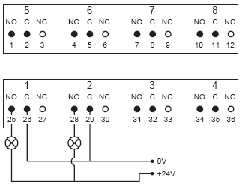
External output

Digital input
There are 8 optically isolated inputs. The internal supply and ground are galvanic isolated, providing a possibility to use for instance a pushbutton as signal.
Connector
20-pin detachable screw terminal. Mating connector Phoenix MCVR 1.5/10-ST-3.81 or compatible.
Function
Isolated optocoupled digital inputs. Logical function is set in the configuration of the PowerFocus.
Electrical data
According to IEC 61131-2.
Pos. No. | Function |
|---|---|
15 | digital input 5 + |
16 | digital input 5 – |
17 | digital input 6 + |
18 | digital input 6 – |
19 | digital input 7 + |
20 | digital input 7 – |
21 | digital input 8+ |
22 | digital input 8 – |
23 | +24 VDC isolated |
24 | GND (+24 VDC isolated) |
|
|
39 | digital input 1+ |
40 | digital input 1 – |
41 | digital input 2+ |
42 | digital input 2 – |
43 | digital input 3+ |
44 | digital input 4 – |
45 | digital input 4+ |
46 | digital input 4 – |
47 | +24 VDC isolated |
48 | GND (+24 VDC isolated) |
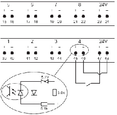
Operator panel
The operator panel is connected to the I/O bus and provides a configurable digital communication link between an operator and the controller. Lamps, buttons, buzzer, and switches are used in the communication. Read the operator panel documentation for address configuration and specifications of connections.
Stacklight
The stacklight can be configured to display the I/O signals from the controller.
The stacklight can be customized as follows:
A stack of four lights. One optional light can be added to this stack. You can also customize the order and the color of lights.
Two positions, A and B, which can be customized with indicator lamps or switches.
A buzzer placed on the side of the box that has a fixed frequency of 3000 Hz. The buzzer can be configured to activate on any tightening controller signal.
Two external outputs, two external inputs and a connector for external power.
Two I/O bus connectors. A termination plug, should be applied to the second I/O bus connector if it is at the end of the I/O bus line. The I/O bus termination plug is listed in the accessory list.
Indicatorbox
The Indicatorbox is a flexible display indicator used to display status signals from the controller. The display is equipped with 20 dual color LEDs, these are mounted in a square with five LEDs at each side.
Scanner
In this menu, scanner configurations can be added. Scanners can be configured to either have scanned strings handled by the controller, or passed through to a an external system. When the scanned string is passed through, the controller does not select a task based on the string, but instead passes the string to an external device via an output signal.
Adding a scanner and enabling pass through
Go to Configurations > Scanner, and click on the Plus sign at the top right.
Give the scanner configuration a name.
To enable pass through, click on Edit, and set Pass Through Mode to On.
General Virtual Station
In General Virtual Station, different specific result reporting and tightening settings can be saved. Different filters can be created, filtering out specific results. In the tightening settings, characteristics like the tool unlocking behavior can be set. These configurations can then be assigned to virtual stations.
Adding and editing a configuration
In the Configurations menu, select the General Virtual Station tab, and then select the plus icon in the top right corner.
Give the new configuration a name and select Edit.
In the Result filter for reporting window, set the switch to On for those parameters you want to include in the results. By default, all parameters are set to On.
Turning on a result filter prevents the respective result from being sent, but the result is still shown on the controller.
The following parameters can be set in the Result filter for reporting section:
Loosening
Batch increment
Batch decrement
Reset batch
Bypass Tightening Program
Abort sequence
Abort not started sequence
Reset batch sequence
In the Tightening Settings window, set a value for any of the parameters listed. By default, all parameters are set to Off.
The following parameters can be set in the Tightening Settings section:
Unlock tool on loosening - makes sure that the tool is locked after a NOK tightening.
Disable loosening - makes sure that an operator is not loosening a bolt that their processes do not allow to be loosened.
Disable tightening - makes sure that an operator is not tightening a bolt that their processes do not allow to be tightened.
Setting | Description |
|---|---|
Off | A disabled tool will remain disabled regardless of the loosening status. |
On OK | A disabled tool will be unlocked after an OK loosening has been performed. |
Always | A disabled tool will be unlocked as soon as a loosening has been performed, regardless of the loosening status. |
Disable loosening settings
To ensure that a bolt cannot be loosened by mistake, use the disable loosening function. There are four disable loosening settings:
Setting | Description |
|---|---|
Off | Loosening is always enabled. It is always possible to loosen a bolt. |
On OK tightening | Loosening is disabled after an OK tightening. It is not possible to loosen a correct tightened bolt. |
On NOK tightening | Loosening is disabled after an NOK tightening. It is not possible to loosen a not correct tightened bolt. |
Always | Loosening is always disabled. It is not possible to loosen a bolt. |
These settings are valid during the execution of a task. Loosening enables and disables depending on the setting and the status of the last tightening. For a new task the start state for disable loosening is set as follows:
Setting | Description |
|---|---|
Off | Loosening enabled. It is possible to loosen a bolt. |
On OK tightening | Loosening disabled. It is not possible to loosen a bolt. |
On NOK tightening | Loosening disabled. It is not possible to loosen a bolt. |
After every tightening | Loosening disabled. It is not possible to loosen a bolt. |
The start state applies whenever a new task is assigned to a Virtual station or when a task starts again. The start state can differ depending on the type of task, described as follows.
Setting | Start state for new task |
|---|---|
Off | Loosening enabled. It is possible to loosen a bolt. |
On OK Tightening | Loosening disabled. It is not possible to loosen a bolt. |
On NOK Tightening | Loosening disabled. It is not possible to loosen a bolt. |
Always | Loosening disabled. It is not possible to loosen a bolt. |
The start state applies whenever a new task is assigned to a Virtual station or when a task starts again. The start state can differ depending on the type of task, described as follows.
Tightening program and Sync mode
Enable and disable of loosening follows the disable loosening setting and is set to the status of the last tightening.
Batch Sequence
During a batch sequence the enable or disable of loosening follows the disable loosening setting and is set to the status of the last tightening. This also applies when a batch goes to the next one within a batch sequence. If a batch sequence starts again, the loosening is enabled or disabled according to the start state for a new task.
Source Batch
Enable and disable of loosening follow the same procedure as described in Batch sequence. If an ongoing source batch starts again or if a new one is selected, the loosening is enabled or disabled according to the start state for new task.
Source Tightening (No batch control)
During a batch, enable and disable is set according to the status of the last tightening. If another program is selected, enable and disable is set according to the start state for new task. If any change of program, tool or socket is done, enable and disable is set according to the start state for new task.
Multispindle tightening
Enable and disable of loosening always follows the status of the last tightening. This is also applicable for a new sync mode.
Disable tightening settings
To make sure that an operator does not tighten a bolt by mistake there is a function called disable tightening. There are four disable tightening settings:
Setting | Description |
|---|---|
Off | Tightening is always enabled. It is always possible to tighten a bolt. |
On OK tightening | Tightening is disabled after an OK tightening. It is not possible to tighten a correct tightened bolt. |
On NOK tightening | Tightening is disabled after an NOK tightening. It is not possible to tighten a not correct tightened bolt. |
Always | Tightening is always disabled. It is not possible to tighten a bolt. |
These settings are valid during the execution of a task. Tightening enables and disables depending on the setting and the status of the last tightening. For a new task the start state for disable tightening is set as follows:
Setting | Start state for new task |
|---|---|
Off | Tightening enabled |
On OK Tightening | Tightening enabled |
On NOK Tightening | Tightening enabled |
Always | Tightening disabled |
The start state applies whenever a new task is assigned to a Virtual station or when the task starts again. The start state can differ depending on the type of task, as described in the Disable Loosening settings section.
Allowing a disabled tool to unlock after loosening
In the general virtual station configuration assigned to the virtual station to which the tool is connected, set the Unlock tool on loosening to On OK or Always.
To enable the setting above, the following conditions need to be met:
The Disable loosening parameter cannot be set to Off or Always.
The Disable loosening parameter cannot be set to the same value as Disable tightening.
The tightening program used must have loosening enabled.
When the tool is locked for either tightening or loosening due to a disable state, it can be unlocked by any of the following input signals:
It is not possible to unlock a disabled tool with the input signals ifLock tool on loosening is set to Always.
Assigning a configuration to a virtual station
Each virtual station can have its own configuration and multiple virtual stations can share the same configuration. A configuration must be assigned to a virtual station to become active.
Go to the Virtual Station menu and select the Virtual Station to which you want to assign the configuration.
Under General, the first configuration is selected by default. Select the configuration name.
In the pop-up window, select a configuration from the list. The pop-up window closes upon selection.
PF6 FlexSystem menu

IAM
The Intelligent Application module (IAM) is a non volatile storage that is located in the controller. The storage module contains all the controller programs, configurations and results. Certain modules may also include additional loaded feature items.
Parameter | Description |
|---|---|
Name | Used as an identifier when connecting the system to ToolsTalk 2. |
IAM information | Information on the FlexIAM |
Software
Software is used to load new system software.
Parameter | Description |
|---|---|
Current version | Information on the current software version. |
Stored version | Information on the stored software version. |
Software activation | Select which software version to use, current or stored. |
Software update | Update software by clicking the Browse button. |
To update the software perform the following steps:
Open the web GUI.
Click on the Controller icon.
SelectPF6 FlexSystem.
In the Software update field click on the Browse button.
Locate the new software. It is bundled in a zip-file.
Click Continue.
Follow the instructions on the screen.
The controller can store two installed software versions, current and stored. By using Software activation, it is possible to choose which software version to use.
The configuration of the active software will not be cloned when you switch to the other software version. That is, any configuration changes in one software will not affect the other installed software.
To activate an installed software:
On the PF6 FlexSystem menu, go to Software.
Swipe Software activation and follow the instructions.
Restart the system.
Hardware
Parameter | Description |
|---|---|
Controller information | Information on the controller |
Battery status | Status of the battery. |
Anybus CC module | Information on the anybus CC module. |
Channels
Channels is used for fault finding. It lists all the channels in the system and show the current status of each one.
Parameter | Description |
|---|---|
Channel 1 | Displays information about FlexDrive and tool on each active channel. |
Channel 2 | |
... |
Export/Import
The Export/Import Tab supports the user to make one of the following operations: Export, Import, and Automated backup.
The Export window supports the user to export controller configurations, settings, results, and events. In addition, it is possible to export tool logs, which can be shared with Atlas Copco Service personnel to troubleshoot problems with the tool(s).
The Import window supports the user to import controller configurations and settings.
It is only possible to have one active Export or Import at the time. Any attempt to start a new Export/Import while there is an ongoing Export/Import is rejected.
The Automated backup window supports the user to generate automatically a backup file.
Export/Import Between Controllers
Controllers may have different IAM types that could have different capabilities.
A controller can export all the configurations that are applicable for the current type of IAM module.
A controller cannot import a file exported from a different type of IAM module. This is applicable also when using ToolsTalk 2.
In this Section
Automated Backup
The Automated Backup window enables or disables sFTP export.
By default, Enable sFTP export switch is set to OFF.
When turning ON Enable sFTP export switch, an export file is created 10 minutes after the last configuration change.
If Enable sFTP export switch is set to ON on system startup, an export file is automatically created within 2-3 minutes. The export file is created within 2-3 minutes to reflect changes that might have been done before the system was shutdown.
The old Backup file is deleted before the new Backup file is available.
The data in the exported file include all configurations and settings of the controller.
The sFTP users can retrieve the exported file stored in the following directory of the system: /Export/<export file name>.
A system supporting sFTP is needed.
To retrieve the file sFTP users do not need to use any password.
The username for sFTP users is as follows:
Username | autoexport |
Reports menu

In the Reports menu information regarding Events is displayed. This menu is useful for fault finding.
For detailed information of events:
-
Click on View all events to display a list of the latest events that occurred in the system.
-
Select one event to get more detailed information about the event.
Settings menu

The Settings menu is used to configure the IP address of the FlexController and set how the FlexController connects to ToolsTalk 2. It is also used to change the date and time of the system.
Network
The Ethernet ports pane includes an illustration that points out the service ethernet port and the factory ethernet port.
Parameter | Description |
|---|---|
Factory ethernet port | Set the IP address, subnet mask and gateway manually or via DHCP. |
Service ethernet port | The static IP-address of the service ethernet port is displayed. |
Firewall | See Setting up the Firewall for details. |
Server connections
Parameter | Description |
|---|---|
ToolsTalk | Turn the connection ToolsTalk on or off. |
ToolsNet | Turn the connection ToolsNet on or off. |
Atlas Copco license manager | Turn the communication with the Atlas Copco license manager on or off. |
Remote Logging | Turn the communication with the remote logging server on or off. |
Configuring the Log Levels
On the home view, got the Settings tab and select Server connection on the left pane.
On the Remote logging window, select Configure.
On the Configure events window, select the applicable check boxes.
Category
SysLog classification
Error
Alert, Critical, Emergency, Error
Warning
Warning
Info
Informational, Notice
To restore the selection to the previous configuration, select UNDO.
Select Apply.
Preferences
This is where you set the date and time for the FlexSystem.
Parameter | Description |
|---|---|
Date and time | Select the source of the systems date and time.
|
Language | Choose a language from the list. |
Torque units | Choose a unit from the list. |
Temperature units | Select in which unit the temperature should be displayed. |
Accessibility | Turn the access through the factory port on or off. |
PIN
Set if PIN should be active and after how long it should turned on. Refer to Set PIN protection on the FlexSystem.
Alarms
Alarms are set to control when to perform maintenance or calibration on the tools connected to the system.
The tool service interval and other information are found in the tool view in the Tool menu.
Field | Description |
|---|---|
Service indicator alarm | Enables an alarm for when the service interval is reached. |
Calibration alarm | Enables the tool calibration alarm for all tools connected to the controller. |
Enabling an alarm
Go to the Settings menu.
Open the Alarms menu.
Set On for the chosen alarm to enable it.
Events
It is possible to configure the events available in the controller as either or several of:
Acknowledged
Logged
Displayed
Fieldbus
Field | Description |
|---|---|
Fieldbus type | Indicates the fieldbus type in use. |
Connection status | Indicates the fieldbus connection status: online or offline. |
Extended logging
The FlexController automatically creates logs and stores them. These logs can be configured to include extended logging using log groups.
Reset
Field | Description |
|---|---|
Factory Reset Controller | Click Reset to clear:
You will need to confirm the action in a following confirmation message. The controller will restart at the end of the process. |
Clear Results | Click Clear to clear:
Settings and configurations will remain. You will need to confirm the action in a following confirmation message. The controller will restart at the end of the process. |
In this Section
Setting up the Firewall
The controller can be set up to use a firewall. The firewall is based on the trusted host principle, and only allows incoming connections via ports that are enabled, or addresses that are whitelisted.
By default, the firewall is disabled.
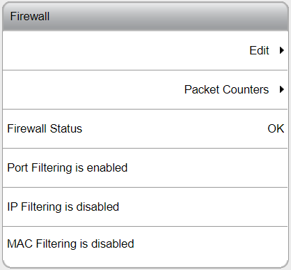
The firewall applies only to incoming connections on the Factory Ethernet Port.
Activating and configuring the firewall
From the home menu select Settings.
Select Network and scroll down to Firewall.
To activate and configure the firewall, select Edit.
Set Off to On to activate the firewall.
Set the remaining features:
Port Filtering (layer 4 firewall)
IP Filtering (layer 3 firewall)
MAC Filtering (layer 2 firewall)
When activating the general firewall feature, Port Filtering (layer 4 firewall) and all its predefined services are enabled by default.
A connection is allowed, when any of the firewall layers accepts it. When no firewall layer is enabled, all incoming connections are allowed through.
Further firewall configuring is done by enabling/disabling connections through the predefined services specified, by adding TCP or UDP ports manually and/or by whitelisting IP/MAC addresses.
Port Filtering (layer 4 firewall)
When Port Filtering (layer 4 firewall) is enabled, the following predefined services are shown with their respective On / Off switches:
Open ports for web (TCP 80, TCP 8080)
Open ports for SSH and SFTP (TCP 22)
Open ports for wireless tools (UDP 6677, TCP 6678)
Open ports for accessories (TCP 25000)
Predefined service | Description |
|---|---|
Open ports for web (TCP 80, TCP 8080) | Ports required for web services so the controller is accessible over the factory network. Setting Open ports for web (TCP 80, TCP 8080) to Off, triggers a warning that the connection with the Web HMI can be lost. |
Open ports for SSH and SFTP (TCP 22) | Port required for SSH and SFTP functionality on the Factory Ethernet Port. |
Open ports for accessories (TCP 25000) | Ports required for accessories to communicate with the controller over the factory network. |
Adding additional TCP and UDP ports
Any additional TCP and UDP ports can be added in their respective entry boxes, that is Open additional TCP ports and Open additional UDP ports. Accepted are both comma-separated ports and port ranges using a dash (-). Example: when entering 1,2,3,4-10, all ports between 1 and 10 are opened.
Invalid port entries trigger an immediate pop-up warning.
Ports are automatically sorted after pressing the Apply button.
Open Protocol and NTP
When using Open Protocol, the ports to be opened must be added manually in the Open additional TCP ports entry box. For example: 4545,4546,4547 (depending on the ports configured in Virtual Station > Virtual Station 1 > Protocols > Open Protocol > Server Port). When using an NTP server, port 123 must be added manually in the Open additional UDP ports entry box.
Multiple ports can be added by using comma separation. Port ranges can be added by using a dash.
IP Filtering (layer 3 firewall)
IP Filtering (layer 3 firewall) allows specifying trusted hosts or networks by entering their IP addresses in the IP White List entry box. To access the entry box, set the switch to On. Accepted entries are lists of IP addresses or network addresses in the form of IP tables, that is, host IP addresses or network IP addresses. The network mask can be entered as mask length (for example, /24) or as network IP address (for example, /255.255.255.0). Packets coming from a whitelisted IP address are immediately allowed. Other packets are screened by the other firewall layers (Port Filtering and MAC Filtering).
Due to security issues, entering host names or network names is not accepted.
Note that processes like NATing (Network Address Translation) may change source IP addresses. Consult your local network administrator when whitelisting a host based on source IP address is required.
MAC Filtering (layer 2 firewall)
MAC Filtering (layer 2 firewall) allows specifying trusted hosts or networks by entering their MAC addresses in the MAC White List entry box. To access the entry box, set the switch to On. Accepted entries are comma-separated lists of MAC addresses. Packets coming from a whitelisted MAC address are immediately allowed. Other packets are screened by the other firewall layers (Port Filtering and IP Filtering).
Invalid entries trigger an immediate pop-up warning.
Note that routing may change source MAC addresses. Consult your local network administrator when whitelisting a host based on source MAC address is required.
Packet counters
To view the packet counter values for each firewall layer, select Packet Counters. To refresh or reset the packet counter values, select the corresponding switch and release.
Firewall status
The status of the general firewall feature and its firewall layers is shown in the Firewall main view directly under Settings > Network.
Status | Description |
|---|---|
OK | The firewall is enabled and the firewall configuration is applied. |
Disabled | The firewall is disabled and the firewall configuration is not applied. |
Configuration Error | The firewall is enabled, but the firewall configuration is not applied due to an internal error. For safety reasons, the fail-open policy is applied, meaning all connections are allowed through. |
When the general firewall status is OK, the status (Enabled / Disabled) for the respective firewall layers is also shown.
License assignment

Many features and functions in the controller require a license in order to be assigned and used by a virtual station. In the License assignment menu it is possible to synchronize licenses and see current licenses status. The following types are available:
Virtual station types
Fixed collection of features bundled together in a single package. The Virtual Station Type determines, among other things, what tools can be run, how many programs and sequences can be used, which tightening strategies are available, and the type of reporting that can be done. The features contained in each Virtual Station Type are features that often are used in conjunction with each other, or which have internal dependencies that require the presence of other features in the package. Virtual Station Types are assigned in their entirety to a virtual station. The virtual station can then make use of all features contained in the Virtual Station Type. In order to be able to perform tightenings, a Virtual Station has to be assigned a Virtual Station Type license. Depending on the license type, various tightening options will be enabled or blocked.
Sync functionalities
Works in the same way as described in Virtual Station Type but used for fixtured systems.
Virtual station features
Individual features which can complement Virtual Station Types. A lot of features can be purchased as a single license.
Controller features
Features that are controller-wide. These are features which are assigned to a controller and once assigned can be used by all virtual stations on that controller.
Source Overview
The Source Overview tab, License assignment > Source Overview, provides the user with an overview of the licenses installed on the controller, as well as where they were installed from. A maximum number of 10 different sources can be displayed here, and each will be designated with FMS P (for FMS Portable, or dongle), or License Server (TT2).
Live results

The live result icon locates at the bottom of the home page. The live result window shows results from the different virtual stations on the controller in the upper four as well as the lower four panes. The reason for this is that you can choose two different result views for the same virtual station to be shown at the same time.
Click a result pane to open a window where you can step through the different result views by clicking the arrows at the side of the result window.
In this Section
Result View - Numbers
The first window will display the result in numbers.

1 | Virtual station name |
2 | Batch sequence name |
3 | Batches in sequence
|
4 | Tightenings in batch
|
5 | Result status An NOK tightening will give a detailed status of the unsuccessful tightening. |
6 | Target torque/angle |
7 | Tightening program name |
8 | Number of completed batches in sequence |
9 | Number of completed tightenings in a batch |
10 | Tightening result |
Result View - Identifier Strings
This result view shows the identifier strings included in a multiple barcode scan.
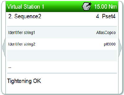
Operation
In this section, you can find step-by-step information about how to operate the product.
General operation
Do not place anything on top of the FlexSystem.
Make sure you know where the emergency stop (e-stop) is located and how to initiate a system start.
Wait at least 30 seconds between power off and power on when you restart the FlexSystem.
LED indicators
The FlexSystem light indicators are used to indicate if the system is running in normal mode, if a failure occurred or when it is time for service.
Status | Description | FlexCarrier | FlexController | FlexDrive | FlexDrive |
|---|---|---|---|---|---|
| |||||
| |||||
| |||||
| |||||
| |||||
| |||||
Booting | The red and green lights are on until the software is up and running. |  |  |  | |
| |||||
Normal operation | A constant green light on the FlexCarrier during normal operation indicates that the power is on. |  |  |  | |
| |||||
Channel error | A red flashing light on the FlexDrive indicates a channel error. The green light on the FlexCarrier indicates that the power is on. | | | | |
Change FlexIAM
Make sure that the power, 3-phase and 24 VDC, is off when you change the FlexIAM.

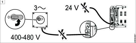


Reference
In this section, you can find miscellaneous useful information.
Input Signals
Abort Sequence - 10012
When a Batch sequence abort request is received, the Batch sequence functionality aborts the batch sequence only after getting the ongoing tightening result.
Name in SoftPLC: ABORT_BATCH_SEQUENCE
Signal Type | Value Type | Size Min [bit] | Size Max [bit] |
|---|---|---|---|
Event | Boolean | 1 | 1 |
Devices
Fieldbus: TRUE
Indicator Box: FALSE
Internal I/O: TRUE
Operator Panel: TRUE
Tool Functions: TRUE
ST Selector: FALSE
Stacklight: TRUE
TLS Tag: FALSE
I/O Expander: TRUE
Abort Sequence and Clear Results - 10127
When signal "Abort sequence and clear results" is set, the ongoing sequence is aborted and signals related to "Clear results" are cleared.
Name in SoftPLC:ABORT_SEQ_AND_CLEAR_RES
Signal Type | Value Type | Size Min [bit] | Size Max [bit] |
|---|---|---|---|
State | Boolean | 1 | 1 |
Devices
Fieldbus: TRUE
Indicator Box: FALSE
Internal I/O: TRUE
Operator Panel: TRUE
Tool Functions: TRUE
ST Selector: FALSE
Stacklight: TRUE
TLS Tag: FALSE
I/O Expander: TRUE
Acknowledge Events - 10004
Acknowledge of an event.
Name in SoftPLC: ACKNOWLEDGE_EVENT
Signal Type | Value Type | Size Min [bit] | Size Max [bit] |
|---|---|---|---|
Event | Boolean | 1 | 1 |
Devices
Fieldbus: TRUE
Indicator Box: FALSE
Internal I/O: TRUE
Operator Panel: TRUE
Tool Functions: TRUE
ST Selector: FALSE
Stacklight: TRUE
TLS Tag: FALSE
I/O Expander: TRUE
Activate Tool Scanner - 10075
Activates the tool scanner through an external source.
Name in SoftPLC: ACTIVATE_TOOL_SCANNER
Signal Type | Value Type | Size Min [bit] | Size Max [bit] |
|---|---|---|---|
Event | Boolean | 1 | 1 |
Devices
Fieldbus: TRUE
Indicator Box: FALSE
Internal I/O: TRUE
Operator Panel: TRUE
Tool Functions: TRUE
ST Selector: FALSE
Stacklight: TRUE
TLS Tag: FALSE
I/O Expander: TRUE
Batch Decrement - 10002
Incrementally decreases the batch counter by one.
Name in SoftPLC: BATCH_DECREMENT
Signal Type | Value Type | Size Min [bit] | Size Max [bit] |
|---|---|---|---|
Event | Boolean | 1 | 1 |
Devices
Fieldbus: TRUE
Indicator Box: FALSE
Internal I/O: TRUE
Operator Panel: TRUE
Tool Functions: TRUE
ST Selector: FALSE
Stacklight: TRUE
TLS Tag: FALSE
I/O Expander: TRUE
Batch Increment - 10001
Incrementally increases the batch counter by one.
Name in SoftPLC: BATCH_INCREMENT
Signal Type | Value Type | Size Min [bit] | Size Max [bit] |
|---|---|---|---|
Event | Boolean | 1 | 1 |
Devices
Fieldbus: TRUE
Indicator Box: FALSE
Internal I/O: TRUE
Operator Panel: TRUE
Tool Functions: TRUE
ST Selector: FALSE
Stacklight: TRUE
TLS Tag: FALSE
I/O Expander: TRUE
Bypass Identifier - 10123
In source batch string used to bypass an identifier string in string receiving sequence.
Signal Type | Value Type | Size Min [bit] | Size Max [bit] |
|---|---|---|---|
Event | Boolean | 1 | 1 |
Devices
Fieldbus: TRUE
Indicator Box: FALSE
Internal I/O: TRUE
Operator Panel: TRUE
Tool Functions: TRUE
ST Selector: FALSE
Stacklight: TRUE
TLS Tag: FALSE
I/O Expander: TRUE
Bypass Tightening Program - 10008
Skips the next tightening program in the running batch sequence.
Name in SoftPLC: BYPASS_PSET
Signal Type | Value Type | Size Min [bit] | Size Max [bit] |
|---|---|---|---|
Event | Boolean | 1 | 1 |
Devices
Fieldbus: TRUE
Indicator Box: FALSE
Internal I/O: TRUE
Operator Panel: TRUE
Tool Functions: TRUE
ST Selector: FALSE
Stacklight: TRUE
TLS Tag: FALSE
I/O Expander: TRUE
Channel Command - 10054
Channel Command is an input signal that inhibits individual tools and prevents that those tools are included in the next tightening. It is also possible to replace the tightening program or bolt number configured in the sync mode configuration. Up to 64 channels are supported.
Name in SoftPLC: CHANNEL_COMMAND
Signal Type | Value Type | Size Min [bit] | Size Max [bit] |
|---|---|---|---|
State | uint32 array | 1 | 64 |
The signal Channel Command -10054 contains sub-signals (for more information, see "Input Signals: Sub-signals").
Devices
Fieldbus: TRUE
Indicator Box: FALSE
Internal I/O: TRUE
Operator Panel: TRUE
Tool Functions: TRUE
ST Selector: FALSE
Stacklight: TRUE
TLS Tag: FALSE
I/O Expander: TRUE
Continue Step - 10128
Continue Step is an input signal that stops the Wait tightening step.
When the tightening has reached a Wait tightening step with the condition Signal configured as Wait Type, a rising edge of the signal Continue Step causes the system (one or more spindles) to release.
For more information, see the sub-signal Channel Command - 10054: Continue Step.
Name in SoftPLC: CONTINUE_STEP
Signal Type | Value Type | Size Min [bit] | Size Max [bit] |
|---|---|---|---|
Event | Boolean | 1 | 1 |
Devices
Fieldbus: TRUE
Indicator Box: FALSE
Internal I/O: TRUE
Operator Panel: TRUE
Tool Functions: FALSE
ST Selector: FALSE
Stacklight: TRUE
TLS Tag: FALSE
I/O Expander: TRUE
Data Hold - 10124
When signal DATAHOLD is set to true at the end of a tightening, transmission of the result data will be stopped.
Name in SoftPLC: DATAHOLD
Signal Type | Value Type | Size Min [bit] | Size Max [bit] |
|---|---|---|---|
State | Boolean | 1 | 1 |
Devices
Fieldbus: TRUE
Indicator Box: FALSE
Internal I/O: TRUE
Operator Panel: FALSE
Tool Functions: FALSE
ST Selector: FALSE
Stacklight: FALSE
TLS Tag: FALSE
I/O Expander: TRUE
Data Drop - 10125
When set DATADROP to true at the end of a tightening DATADROP signal will drop result from the tightening. The result will not be stored persistently or sent to any device or clients like ToolsNet or protocol adapters.
Name in SoftPLC: DATADROP
Signal Type | Value Type | Size Min [bit] | Size Max [bit] |
|---|---|---|---|
State | Boolean | 1 | 1 |
Devices
Fieldbus: TRUE
Indicator Box: FALSE
Internal I/O: TRUE
Operator Panel: TRUE
Tool Functions: FALSE
ST Selector: FALSE
Stacklight: TRUE
TLS Tag: FALSE
I/O Expander: TRUE
Disable Fieldbus - 10049
Disables the fieldbus.
Name in SoftPLC: DISABLE_FIELDBUS
Signal Type | Value Type | Size Min [bit] | Size Max [bit] |
|---|---|---|---|
State | Boolean | 1 | 1 |
Devices
Filedbus: FALSE
Indicator Box: FALSE
Internal I/O: TRUE
Operator Panel: TRUE
Tool Functions: FALSE
ST Selector: FALSE
Stacklight: TRUE
TLS Tag: FALSE
I/O Expander: TRUE
Disable Loosening at OK Tight - 20022
This lock signal is used to disable loosening after an OK tightening.
Name in SoftPLC:
Signal Type | Value Type | Size Min [bit] | Size Max [bit] |
|---|---|---|---|
State | Boolean | 1 | 1 |
Devices
Fieldbus: TRUE
Indicator Box: FALSE
Internal I/O: FALSE
Operator Panel: FALSE
Tool Functions: FALSE
ST Selector: FALSE
Stacklight: FALSE
TLS Tag: FALSE
I/O Expander: FALSE
Devices
Fieldbus: TRUE
Indicator Box: FALSE
Internal I/O: FALSE
Operator Panel: FALSE
Tool Functions: FALSE
ST Selector: FALSE
Stacklight: FALSE
TLS Tag: FALSE
I/O Expander: FALSE
Disable Test Bolt - 10057
Name in SoftPLC: DISABLE_TESTBOLT
Converter | Signal Type | Value Type | Size Min [bit] | Size Max [bit] |
|---|---|---|---|---|
Standard | State | Boolean | 1 | 1 |
Invert | State | Boolean | 1 | 1 |
To avoid duplicating signals, it is possible to define Value Converters.
Converters are used to support more than one representation of the same signal (for example Angle/Torque Status can both be represented bitwise or as a status character).
Devices
Fieldbus: TRUE
Indicator Box: FALSE
Internal I/O: TRUE
Operator Panel: TRUE
Tool Functions: FALSE
ST Selector: FALSE
Stacklight: TRUE
TLS Tag: FALSE
I/O Expander: TRUE
Disable tool - 30000
If the signal is set to True, a tool is immediately stopped and locked.
Converter | Signal Type | Value Type | Size Min [bit] | Size Max [bit] |
|---|---|---|---|---|
Standard | State | Boolean | 1 | 1 |
Invert | State | Boolean | 1 | 1 |
To avoid duplicating signals, it is possible to define Value Converters.
Converters are used to support more than one representation of the same signal (for example Angle/Torque Status can both be represented bitwise or as a status character).
Devices
Fieldbus: TRUE
Indicator Box: FALSE
Internal I/O: FALSE
Operator Panel: FALSE
Tool Functions: FALSE
ST Selector: FALSE
Stacklight: FALSE
TLS Tag: FALSE
I/O Expander: FALSE
Disable Tool Scanner - 10119
Disables tool scanner when scanning by tool trigger when signal is set. It is still possible to scan by using the scan button but the scan string is ignored.
Name in SoftPLC: DISABLE_TOOL_SCANNER
Signal Type | Value Type | Size Min [bit] | Size Max [bit] |
|---|---|---|---|
State | Boolean | 1 | 1 |
Devices
Fieldbus: TRUE
Indicator Box: FALSE
Internal I/O: TRUE
Operator Panel: TRUE
Tool Functions: FALSE
ST Selector: FALSE
Stacklight: TRUE
TLS Tag: TRUE
I/O Expander: TRUE
Dynamic Batch Size - 10074
Name in SoftPLC: DYNAMIC_BATCH_SIZE
Signal Type | Value Type | Size Min [bit] | Size Max [bit] |
|---|---|---|---|
State | Integer | 1 | 16 |
Devices
Fieldbus: TRUE
Indicator Box: FALSE
Internal I/O: FALSE
Operator Panel: FALSE
Tool Functions: FALSE
ST Selector: FALSE
Stacklight: FALSE
TLS Tag: FALSE
I/O Expander: FALSE
Enable Operation - 10055
Name in SoftPLC: ENABLE_OPERATION
Converter | Signal Type | Value Type | Size Min [bit] | Size Max [bit] |
|---|---|---|---|---|
Standard | State | Boolean | 1 | 1 |
Invert | State | Boolean | 1 | 1 |
To avoid duplicating signals, it is possible to define Value Converters.
Converters are used to support more than one representation of the same signal (for example Angle/Torque Status can both be represented bitwise or as a status character).
Devices
Fieldbus: TRUE
Indicator Box: FALSE
Internal I/O: TRUE
Operator Panel: TRUE
Tool Functions: FALSE
ST Selector: FALSE
Stacklight: TRUE
TLS Tag: FALSE
I/O Expander: TRUE
External OK - 10063
Name in SoftPLC: EXTERNAL_OK
Signal Type | Value Type | Size Min [bit] | Size Max [bit] |
|---|---|---|---|
Event | Boolean | 1 | 1 |
Devices
Fieldbus: TRUE
Indicator Box: FALSE
Internal I/O: TRUE
Operator Panel: TRUE
Tool Functions: FALSE
ST Selector: FALSE
Stacklight: TRUE
TLS Tag: FALSE
I/O Expander: TRUE
Fieldbus AsyncData To PF - 10077
Name in SoftPLC:
Signal Type | Value Type | Size Min [bit] | Size Max [bit] |
|---|---|---|---|
State | uint8 array | 16 | 2048 |
Devices
Fieldbus: TRUE
Indicator Box: FALSE
Internal I/O: FALSE
Operator Panel: FALSE
Tool Functions: FALSE
ST Selector: FALSE
Stacklight: FALSE
TLS Tag: FALSE
I/O Expander: FALSE
Fieldbus Lock Loosening - 20021
A Virtual Station is locked when starting a loosening if the signal is set from a connected and supported accessory.
An ongoing loosening is aborted immediately when Fieldbus Lock Loosening is set to True, due to the Stop Drive setting.
Converter | Signal Type | Value Type | Size Min [bit] | Size Max [bit] |
|---|---|---|---|---|
Standard | State | Boolean | 1 | 1 |
Invert | State | Boolean | 1 | 1 |
To avoid duplicating signals, it is possible to define Value Converters.
Converters are used to support more than one representation of the same signal (for example Angle/Torque Status can both be represented bitwise or as a status character).
Devices
Fieldbus: TRUE
Indicator Box: FALSE
Internal I/O: FALSE
Operator Panel: FALSE
Tool Functions: FALSE
ST Selector: FALSE
Stacklight: FALSE
TLS Tag: FALSE
I/O Expander: FALSE
Fieldbus Lock Tightening - 20020
A Virtual Station is locked when starting a tightening if the signal is set from a connected and supported accessory.
An ongoing tightening is aborted immediately when Fieldbus Lock Tightening is set to True, due to the Stop Drive setting.
Converter | Signal Type | Value Type | Size Min [bit] | Size Max [bit] |
|---|---|---|---|---|
Standard | State | Boolean | 1 | 1 |
Invert | State | Boolean | 1 | 1 |
To avoid duplicating signals, it is possible to define Value Converters.
Converters are used to support more than one representation of the same signal (for example Angle/Torque Status can both be represented bitwise or as a status character).
Devices
Fieldbus: TRUE
Indicator Box: FALSE
Internal I/O: FALSE
Operator Panel: FALSE
Tool Functions: FALSE
ST Selector: FALSE
Stacklight: FALSE
TLS Tag: FALSE
I/O Expander: FALSE
Flush Read Result Queue - 30005
Signal Type | Value Type | Size Min [bit] | Size Max [bit] |
|---|---|---|---|
Event | Boolean | 1 | 1 |
Devices
Fieldbus: TRUE
Indicator Box: FALSE
Internal I/O: FALSE
Operator Panel: FALSE
Tool Functions: FALSE
ST Selector: FALSE
Stacklight: FALSE
TLS Tag: FALSE
I/O Expander: FALSE
ID for Dynamic Batch Size - 10073
Name in SoftPLC: DYNAMIC_BATCH_SIZE_TPID
Converter | Signal Type | Value Type | Size Min [bit] | Size Max [bit] |
|---|---|---|---|---|
Standard | State | Integer | 1 | 16 |
TreatZeroAsOne | State | Integer | 1 | 16 |
To avoid duplicating signals, it is possible to define Value Converters.
Converters are used to support more than one representation of the same signal (for example Angle/Torque Status can both be represented bitwise or as a status character).
Devices
Fieldbus: TRUE
Indicator Box: FALSE
Internal I/O: FALSE
Operator Panel: FALSE
Tool Functions: FALSE
ST Selector: FALSE
Stacklight: FALSE
TLS Tag: FALSE
I/O Expander: FALSE
Lock Loosening - 20003
Signal Type | Value Type | Size Min [bit] | Size Max [bit] |
|---|---|---|---|
State | Boolean | 1 | 1 |
Devices
Filedbus: FALSE
Indicator Box: FALSE
Internal I/O: TRUE
Operator Panel: TRUE
Tool Functions: FALSE
ST Selector: FALSE
Stacklight: TRUE
TLS Tag: FALSE
I/O Expander: TRUE
Lock Tightening - 20002
Tool locked for tightening by digital input.
Signal Type | Value Type | Size Min [bit] | Size Max [bit] |
|---|---|---|---|
State | Boolean | 1 | 1 |
Devices
Filedbus: FALSE
Indicator Box: FALSE
Internal I/O: TRUE
Operator Panel: TRUE
Tool Functions: FALSE
ST Selector: FALSE
Stacklight: TRUE
TLS Tag: FALSE
I/O Expander: TRUE
Lock Tool Active High - 20004
Signal Type | Value Type | Size Min [bit] | Size Max [bit] |
|---|---|---|---|
State | Boolean | 1 | 1 |
Devices
Filedbus: FALSE
Indicator Box: FALSE
Internal I/O: TRUE
Operator Panel: TRUE
Tool Functions: FALSE
ST Selector: FALSE
Stacklight: TRUE
TLS Tag: FALSE
I/O Expander: TRUE
Lock Tool Active Low - 20061
Locks the tool when this signal is low.
Signal Type | Value Type | Size Min [bit] | Size Max [bit] |
|---|---|---|---|
State | Boolean | 1 | 1 |
Devices
Filedbus: FALSE
Indicator Box: FALSE
Internal I/O: TRUE
Operator Panel: TRUE
Tool Functions: FALSE
ST Selector: FALSE
Stacklight: TRUE
TLS Tag: FALSE
I/O Expander: TRUE
Manual Mode - 10061
Used to set the Virtual Station in manual mode.
If the signal is True (high) the signal 101 - Manual mode is high.
If the signal is False (low) the signal 101 - Manual mode is low.
Name in SoftPLC: SET_MANUAL_MODE
Converter | Signal Type | Value Type | Size Min [bit] | Size Max [bit] |
|---|---|---|---|---|
Standard | State | Boolean | 1 | 1 |
Invert | State | Boolean | 1 | 1 |
To avoid duplicating signals, it is possible to define Value Converters.
Converters are used to support more than one representation of the same signal (for example Angle/Torque Status can both be represented bitwise or as a status character).
Relevant Information
Devices
Fieldbus: TRUE
Indicator Box: FALSE
Internal I/O: TRUE
Operator Panel: TRUE
Tool Functions: FALSE
ST Selector: FALSE
Stacklight: TRUE
TLS Tag: FALSE
I/O Expander: TRUE
Master Unlock - 10005
Master Unlock is an input signal which unlocks the following functions and signals.
FUNCTIONS:
Disable loosening at OK tightening
Disable loosening at NOK tightening
Disable tightening
Max consecutive NOK
Tool Lock on Sequence complete
SIGNALS:
20001 - Pending Event Acknowledge Lock
20002 - Lock Tightening
20003 - Lock Loosening
20004 - Lock Tool Active High
20013 - WorkTask Lock Tightening
20014 - WorkTask Lock Loosening
20015 - Batch Done lLock
20018 - Open Protocol Lock
20020 - Fieldbus Lock Tightening
20021 - Fieldbus Lock Loosening
20022 - Disable Loosening At OK Tight
20023 - Too Many NOK Tightenings Lock
20033 - Line Control Lock
20034 - Locked By Alternative Identifier
Name in SoftPLC: MASTER_UNLOCK
Signal Type | Value Type | Size Min [bit] | Size Max [bit] |
|---|---|---|---|
Event | Boolean | 1 | 1 |
Devices
Fieldbus: TRUE
Indicator Box: FALSE
Internal I/O: TRUE
Operator Panel: TRUE
Tool Functions: TRUE
ST Selector: FALSE
Stacklight: TRUE
TLS Tag: FALSE
I/O Expander: TRUE
Pulse Stop - 10030
If this signal is generated any ongoing tightening or loosening will be stopped. Used in combination with 10024 or 10072.
Name in SoftPLC: TIGHTENING_STOP_PULSE
Signal Type | Value Type | Size Min [bit] | Size Max [bit] |
|---|---|---|---|
State | Boolean | 1 | 1 |
Devices
Fieldbus: TRUE
Indicator Box: FALSE
Internal I/O: TRUE
Operator Panel: TRUE
Tool Functions: FALSE
ST Selector: FALSE
Stacklight: TRUE
TLS Tag: FALSE
I/O Expander: TRUE
Read Result Handshake Ack - 30004
Enable the Read Result Handshake feature in the Fieldbus device for making the controller available for the signal Rear Result Handshake Ack.
Signal Type | Value Type | Size Min [bit] | Size Max [bit] |
|---|---|---|---|
State | Boolean | 1 | 1 |
Devices
Fieldbus: TRUE
Indicator Box: FALSE
Internal I/O: FALSE
Operator Panel: FALSE
Tool Functions: FALSE
ST Selector: FALSE
Stacklight: FALSE
TLS Tag: FALSE
I/O Expander: FALSE
Reset All Identifiers - 10115
In Source batch string used to reset all received string identifiers from string receiving sequence at once. In other worktasks clears VIN number.
Name in SoftPLC: RESET_ALL_IDENTIFIERS
Signal Type | Value Type | Size Min [bit] | Size Max [bit] |
|---|---|---|---|
Event | Boolean | 1 | 1 |
Devices
Fieldbus: TRUE
Indicator Box: FALSE
Internal I/O: TRUE
Operator Panel: TRUE
Tool Functions: TRUE
ST Selector: FALSE
Stacklight: TRUE
TLS Tag: FALSE
I/O Expander: TRUE
Reset Batch - 10003
Resets the batch counter to 0. No batch OK (nxOK). If batch OK is activated, it will be deactivated.
Name in SoftPLC: RESET_BATCH
Signal Type | Value Type | Size Min [bit] | Size Max [bit] |
|---|---|---|---|
Event | Boolean | 1 | 1 |
Devices
Fieldbus: TRUE
Indicator Box: FALSE
Internal I/O: TRUE
Operator Panel: TRUE
Tool Functions: TRUE
ST Selector: FALSE
Stacklight: TRUE
TLS Tag: FALSE
I/O Expander: TRUE
Reset Batch Sequence - 10053
Resets the Batch Sequence. Unlocks a tool that is locked by Tool Lock on Complete.
Name in SoftPLC: RESET_BATCH_SEQUENCE
Signal Type | Value Type | Size Min [bit] | Size Max [bit] |
|---|---|---|---|
Event | Boolean | 1 | 1 |
Devices
Fieldbus: TRUE
Indicator Box: FALSE
Internal I/O: TRUE
Operator Panel: TRUE
Tool Functions: TRUE
ST Selector: FALSE
Stacklight: TRUE
TLS Tag: FALSE
I/O Expander: TRUE
Reset Bistable Relay - 10022
Reset the bistable relay output.
Name in SoftPLC: RESET_BISTABLE_RELAY
Signal Type | Value Type | Size Min [bit] | Size Max [bit] |
|---|---|---|---|
Event | Boolean | 1 | 1 |
Devices
Fieldbus: TRUE
Indicator Box: FALSE
Internal I/O: TRUE
Operator Panel: TRUE
Tool Functions: FALSE
ST Selector: FALSE
Stacklight: TRUE
TLS Tag: FALSE
I/O Expander: TRUE
Reset Cycle Status - 10056
Name in SoftPLC: RESET_CYCLE_STATUS
Signal Type | Value Type | Size Min [bit] | Size Max [bit] |
|---|---|---|---|
Event | Boolean | 1 | 1 |
Devices
Fieldbus: TRUE
Indicator Box: FALSE
Internal I/O: TRUE
Operator Panel: TRUE
Tool Functions: FALSE
ST Selector: FALSE
Stacklight: TRUE
TLS Tag: FALSE
I/O Expander: TRUE
Reset Latest Identifier - 10114
In Source batch string used to reset latest received string from string receiving sequence. In other worktasks clears VIN number.
Name in SoftPLC: RESET_LATEST_IDENTIFIER
Signal Type | Value Type | Size Min [bit] | Size Max [bit] |
|---|---|---|---|
Event | Boolean | 1 | 1 |
Devices
Fieldbus: TRUE
Indicator Box: FALSE
Internal I/O: TRUE
Operator Panel: TRUE
Tool Functions: TRUE
ST Selector: FALSE
Stacklight: TRUE
TLS Tag: FALSE
I/O Expander: TRUE
Reset Relays - 10120
Resets all signals.
Name in SoftPLC: RESET_RELAYS
Signal Type | Value Type | Size Min [bit] | Size Max [bit] |
|---|---|---|---|
Event | Boolean | 1 | 1 |
Devices
Fieldbus: TRUE
Indicator Box: FALSE
Internal I/O: TRUE
Operator Panel: FALSE
Tool Functions: FALSE
ST Selector: FALSE
Stacklight: FALSE
TLS Tag: FALSE
I/O Expander: TRUE
Reset Sequence Status - 10118
Resets signals Batch Sequence Done/OK/NOK and Sequence Aborted.
Name in SoftPLC: RESET_SEQUENCE_STATUS
Signal Type | Value Type | Size Min [bit] | Size Max [bit] |
|---|---|---|---|
Event | Boolean | 1 | 1 |
Devices
Fieldbus: TRUE
Indicator Box: FALSE
Internal I/O: TRUE
Operator Panel: TRUE
Tool Functions: FALSE
ST Selector: FALSE
Stacklight: TRUE
TLS Tag: FALSE
I/O Expander: TRUE
Reset System Error - 10062
Name in SoftPLC: RESET_SYSTEM_ERROR
Signal Type | Value Type | Size Min [bit] | Size Max [bit] |
|---|---|---|---|
Event | Boolean | 1 | 1 |
Devices
Fieldbus: TRUE
Indicator Box: FALSE
Internal I/O: TRUE
Operator Panel: TRUE
Tool Functions: FALSE
ST Selector: FALSE
Stacklight: TRUE
TLS Tag: FALSE
I/O Expander: TRUE
Reset Too Many NOK - 10013
Reset the batch after receiving lock Too Many NOK
Name in SoftPLC: RESET_TOO_MANY_NOK
Signal Type | Value Type | Size Min [bit] | Size Max [bit] |
|---|---|---|---|
Event | Boolean | 1 | 1 |
Devices
Fieldbus: TRUE
Indicator Box: FALSE
Internal I/O: TRUE
Operator Panel: TRUE
Tool Functions: TRUE
ST Selector: FALSE
Stacklight: TRUE
TLS Tag: FALSE
I/O Expander: TRUE
Select Input - 10020
Selects Tightening Program withing Source Tightening/Batch within sequence.
Name in SoftPLC: SELECT_INPUT_VALUE
Converter | Signal Type | Value Type | Size Min [bit] | Size Max [bit] |
|---|---|---|---|---|
Standard | State | Integer | 1 | 16 |
TreatZeroAsOne | State | Integer | 1 | 1 |
To avoid duplicating signals, it is possible to define Value Converters.
Converters are used to support more than one representation of the same signal (for example Angle/Torque Status can both be represented bitwise or as a status character).
Devices
Fieldbus: TRUE
Indicator Box: FALSE
Internal I/O: FALSE
Operator Panel: FALSE
Tool Functions: FALSE
ST Selector: TRUE
Stacklight: FALSE
TLS Tag: FALSE
I/O Expander: FALSE
Select Input and Dynamic Batch Size - 30007
It is used to set the Batch Size for a specific "Identifier Number" in a Source Tightening Task, running "External batch control".
Batch size can be set to 1-250.
If Batch size is set to 0, it is treated as infinite batch. The user is not able to un-set a Batch back to a state where it has no size, once it has been set.
Converter | Signal Type | Value Type | Size Min [bit] | Size Max [bit] |
|---|---|---|---|---|
Standard | State | Integer | 16 | 16 |
TreatZeroAsOne | State | Integer | 16 | 16 |
To avoid duplicating signals, it is possible to define Value Converters.
Converters are used to support more than one representation of the same signal (for example Angle/Torque Status can both be represented bitwise or as a status character).
Devices
Fieldbus: TRUE
Indicator Box: FALSE
Internal I/O: FALSE
Operator Panel: FALSE
Tool Functions: FALSE
ST Selector: FALSE
Stacklight: FALSE
TLS Tag: FALSE
I/O Expander: FALSE
Select Input Bit 0 - 10016
Name in SoftPLC: SEL_INPUT_BIT_0
Signal Type | Value Type | Size Min [bit] | Size Max [bit] |
|---|---|---|---|
State | Boolean | 1 | 1 |
Devices
Filedbus: FALSE
Indicator Box: FALSE
Internal I/O: TRUE
Operator Panel: TRUE
Tool Functions: TRUE
ST Selector: FALSE
Stacklight: TRUE
TLS Tag: FALSE
I/O Expander: TRUE
Select Input Bit 1 - 10017
Name in SoftPLC: SEL_INPUT_BIT_1
Signal Type | Value Type | Size Min [bit] | Size Max [bit] |
|---|---|---|---|
State | Boolean | 1 | 1 |
Devices
Filedbus: FALSE
Indicator Box: FALSE
Internal I/O: TRUE
Operator Panel: TRUE
Tool Functions: TRUE
ST Selector: FALSE
Stacklight: TRUE
TLS Tag: FALSE
I/O Expander: TRUE
Select Input Bit 2 - 10018
Name in SoftPLC: SEL_INPUT_BIT_2
Signal Type | Value Type | Size Min [bit] | Size Max [bit] |
|---|---|---|---|
State | Boolean | 1 | 1 |
Devices
Filedbus: FALSE
Indicator Box: FALSE
Internal I/O: TRUE
Operator Panel: TRUE
Tool Functions: TRUE
ST Selector: FALSE
Stacklight: TRUE
TLS Tag: FALSE
I/O Expander: TRUE
Select Input Bit 3 - 10019
Name in SoftPLC: SEL_INPUT_BIT_3
Signal Type | Value Type | Size Min [bit] | Size Max [bit] |
|---|---|---|---|
State | Boolean | 1 | 1 |
Devices
Filedbus: FALSE
Indicator Box: FALSE
Internal I/O: TRUE
Operator Panel: TRUE
Tool Functions: TRUE
ST Selector: FALSE
Stacklight: TRUE
TLS Tag: FALSE
I/O Expander: TRUE
Select Input Bit 4 - 10066
Name in SoftPLC: SEL_INPUT_BIT_4
Signal Type | Value Type | Size Min [bit] | Size Max [bit] |
|---|---|---|---|
State | Boolean | 1 | 1 |
Devices
Filedbus: FALSE
Indicator Box: FALSE
Internal I/O: TRUE
Operator Panel: TRUE
Tool Functions: FALSE
ST Selector: FALSE
Stacklight: TRUE
TLS Tag: FALSE
I/O Expander: TRUE
Select Input Bit 5 - 10067
Name in SoftPLC: SEL_INPUT_BIT_5
Signal Type | Value Type | Size Min [bit] | Size Max [bit] |
|---|---|---|---|
State | Boolean | 1 | 1 |
Devices
Filedbus: FALSE
Indicator Box: FALSE
Internal I/O: TRUE
Operator Panel: TRUE
Tool Functions: FALSE
ST Selector: FALSE
Stacklight: TRUE
TLS Tag: FALSE
I/O Expander: TRUE
Select Input Bit 6 - 10068
Name in SoftPLC: SEL_INPUT_BIT_6
Signal Type | Value Type | Size Min [bit] | Size Max [bit] |
|---|---|---|---|
State | Boolean | 1 | 1 |
Devices
Filedbus: FALSE
Indicator Box: FALSE
Internal I/O: TRUE
Operator Panel: TRUE
Tool Functions: TRUE
ST Selector: FALSE
Stacklight: TRUE
TLS Tag: FALSE
I/O Expander: TRUE
Select Input Bit 7 - 10069
Name in SoftPLC: SEL_INPUT_BIT_7
Signal Type | Value Type | Size Min [bit] | Size Max [bit] |
|---|---|---|---|
State | Boolean | 1 | 1 |
Devices
Filedbus: FALSE
Indicator Box: FALSE
Internal I/O: TRUE
Operator Panel: TRUE
Tool Functions: TRUE
ST Selector: FALSE
Stacklight: TRUE
TLS Tag: FALSE
I/O Expander: TRUE
Select Input Bit 8 - 10070
Name in SoftPLC: SEL_INPUT_BIT_8
Signal Type | Value Type | Size Min [bit] | Size Max [bit] |
|---|---|---|---|
State | Boolean | 1 | 1 |
Devices
Filedbus: FALSE
Indicator Box: FALSE
Internal I/O: TRUE
Operator Panel: TRUE
Tool Functions: TRUE
ST Selector: FALSE
Stacklight: TRUE
TLS Tag: FALSE
I/O Expander: TRUE
Select Input Bit 9 - 10071
Name in SoftPLC: SEL_INPUT_BIT_9
Signal Type | Value Type | Size Min [bit] | Size Max [bit] |
|---|---|---|---|
State | Boolean | 1 | 1 |
Devices
Filedbus: FALSE
Indicator Box: FALSE
Internal I/O: TRUE
Operator Panel: TRUE
Tool Functions: TRUE
ST Selector: FALSE
Stacklight: TRUE
TLS Tag: FALSE
I/O Expander: TRUE
Select Loosening - 10029
Selects loosening as default operation mode and used in combination with Start Tools -10028 signal.
Name in SoftPLC: SELECT_LOOSENING
Signal Type | Value Type | Size Min [bit] | Size Max [bit] |
|---|---|---|---|
State | Boolean | 1 | 1 |
Relevant Information
Devices
Fieldbus: TRUE
Indicator Box: FALSE
Internal I/O: TRUE
Operator Panel: TRUE
Tool Functions: FALSE
ST Selector: FALSE
Stacklight: TRUE
TLS Tag: FALSE
I/O Expander: TRUE
Select Next Identifier Number - 10116
It is possible to use the signal Select Next Identifier Number when a task in the virtual station is configured as:
Batch Sequence
Source Tightening
Source Batch
Number Identifier method
String Identifier method
ST Selector configurable functions Take Next and Take Previous enable the input signals Select Next Identifier Number and Select Previous Identifier Number.
Batch Sequence selected as Virtual Station Task
If Free Order switch has been enabled, the signal Select Next Identifier Number can select different batches within the selected sequence.
Before selecting batches, it is mandatory that they have the identifier number assigned. If a batch does not have the identifier number assigned, the signal Select Next Identifier Number cannot select it, even if Free Order switch is enabled.
It enables looping through the batches that have a configured identifier number.
If identifier number is "None", it is possible to select it only after all Batches with configured identifier number are completed.
It is possible to do looping, but 0 is skipped. When a batch is finished, it is no longer selectable.
For example, in case of batches with assigned identifier numbers 1,2,4,5, the signal runs in loop: 1,2,4,5,1,2,4... as long as the batches are not finished.
Source Tightening selected as Virtual Station Task
The signal selects the next identifier number from the list of tightening programs specified in the Source Tightening task.
The selection runs from the currently selected identifier number to the next larger one.
When the biggest identifier number is selected, this signal selects 0; after 0, the signal selects the next bigger identifier number.
If 0 is selected as identifier number, the tool is locked.
If the identifier number has been added to the Source Tightening list, but no tightening program has ever been assigned to it, it is skipped while looping through the Source Tightening list.
If the tightening program is assigned to an identifier number and then it is removed from the list of tightening programs, it is still possible to select this identifier number. In this case, the tool is locked because there is not a specific tightening program.
When Selector Mode switch is set to Confirm, the socket selector needs to be assigned and configured. All tightening programs can be selected, but before running them, appropriate socket must be lifted from the socket selector.
Source Batch selected as Virtual Station Task
In Sources > Batch Sequence > Source Batch, when the identifier method is set to Number, the signal Select Next Identifier Number selects sequences from a list of sequences shown in Source Batch task.
It is possible to do looping through 0. The signal Select Next Identifier Number selects only the identifier numbers assigned to sequences.
For example, if there are 4 sequences available with identifier numbers 1,2,4, and 8, the signal Select Next Identifier Number iterates and selects 1,2,4,8,0,1,2...
The identifier numbers not defined are not selected.
In Sources > Batch Sequence > Source Batch, when the identifier method is set to String, it is necessary to select the sequence through external sources (like scanner or Open Protocol). The signal Select Next Identifier Number is able to select the batches within the selected sequence.
Name in SoftPLC: SELECT_NEXT_ID_NUMBER
Signal Type | Value Type | Size Min [bit] | Size Max [bit] |
|---|---|---|---|
Event | Boolean | 1 | 1 |
Devices
Fieldbus: TRUE
Indicator Box: FALSE
Internal I/O: TRUE
Operator Panel: TRUE
Tool Functions: TRUE
ST Selector: TRUE
Stacklight: TRUE
TLS Tag: FALSE
I/O Expander: TRUE
Select Previous Identifier Number - 10117
It is possible to use the signal Select Previous Identifier Number when a task in the virtual station is configured as:
Batch Sequence
Source Tightening
Source Batch
Number Identifier method
String Identifier method
ST Selector configurable functions Take Next and Take Previous enable the input signals Select Next Identifier Number and Select Previous Identifier Number.
Batch Sequence selected as Virtual Station Task
If Free Order switch has been enabled, the signal Select Previous Identifier Number can select different batches within the selected sequence.
Before selecting batches, it is mandatory that they have the identifier number assigned. If a batch does not have the identifier number assigned, the signal Select Previous Identifier Number cannot select it, even if Free Order switch is enabled.
It enables looping through the batches that have a configured identifier number.
If identifier number is "None", it is possible to select it only after all Batches with configured identifier number are completed.
It is possible to do looping, but 0 is skipped. When a batch is finished, it is no longer selectable.
For example, in case of batches with assigned identifier numbers 1,2,4,5, the signal runs in loop: 5,4,2,1,5,4,2... as long as the batches are not finished.
Source Tightening selected as Virtual Station Task
The signal selects the previous identifier number from the list of tightening programs specified in the Source Tightening task.
The selection runs from the currently selected identifier number to the previous lower one.
When the smallest identifier number is selected, this signal selects 0; after 0, the signal selects the next smaller identifier number.
If 0 is selected as identifier number, the tool is locked.
If the tightening program is assigned to an identifier number and then it is removed from the list of tightening programs, it is still possible to select this identifier number. In this case, the tool is locked because there is not a specific tightening program.
When Selector Mode switch is set to Confirm, the socket selector needs to be assigned and configured. All tightening programs can be selected, but before running them, appropriate socket must be lifted from the socket selector.
Source Batch selected as Virtual Station Task
In Sources > Batch Sequence > Source Batch, when the identifier method is set to Number, the signal Select Previous Identifier Number selects sequences from a list of sequences shown in Source Batch task.
It is possible to do looping through 0. The signal Select Previous Identifier Number selects only the identifier numbers assigned to sequences.
For example, if there are 4 sequences available with identifier numbers 1,2,4, and 8, the signal Select Previous Identifier Number iterates and selects 8,4,2,1,0,8,4...
The identifier numbers not defined are not selected.
In Sources > Batch Sequence > Source Batch, when the identifier method is set to String, it is necessary to select the sequence through external sources (like scanner or Open Protocol). The signal Select Previous Identifier Number is able to select the batches within the selected sequence.
Name in SoftPLC: SELECT_PREVIOUS_ID_NUMBER
Signal Type | Value Type | Size Min [bit] | Size Max [bit] |
|---|---|---|---|
Event | Boolean | 1 | 1 |
Devices
Fieldbus: TRUE
Indicator Box: FALSE
Internal I/O: TRUE
Operator Panel: TRUE
Tool Functions: TRUE
ST Selector: TRUE
Stacklight: TRUE
TLS Tag: FALSE
I/O Expander: TRUE
Set Bistable Relay - 10021
Set the bistable relay output.
Name in SoftPLC: SET_BISTABLE_RELAY
Signal Type | Value Type | Size Min [bit] | Size Max [bit] |
|---|---|---|---|
Event | Boolean | 1 | 1 |
Devices
Fieldbus: TRUE
Indicator Box: FALSE
Internal I/O: TRUE
Operator Panel: TRUE
Tool Functions: FALSE
ST Selector: FALSE
Stacklight: TRUE
TLS Tag: FALSE
I/O Expander: TRUE
Set CCW Direction - 10132
Set CCW Direction is an input signal which forces the SR21/SL tool to counterclockwise direction.
The SR21/SL tool is forced to counterclockwise direction only if, after being connected with the controller, the signal is set "high".
This operation is essential, even if the signal was set "high" before that the SR21/SL tool was connected with the controller.
If the tool is running clockwise, the signal will switch the direction to counterclockwise.
If the tool is running counterclockwise, the direction will not change.
Set CCW Direction overrides the input signal Toggle CW/CCW For Next Run.
If the signal is set "low", the tool will switch the direction to clockwise.
When the tool is set to counterclockwise, the orange direction LED on the tool lights up.
Signal Type | Value Type | Size Min [bit] | Size Max [bit] |
|---|---|---|---|
State | Boolean | 1 | 1 |
Devices
Fieldbus: TRUE
Indicator Box: FALSE
Internal I/O: TRUE
Operator Panel: TRUE
Tool Functions: TRUE
ST Selector: FALSE
Stacklight: TRUE
TLS Tag: FALSE
I/O Expander: TRUE
Socket Selector External Green Light - 10046
Controls green lights when socket selector is in external mode (how multiple physical devices are mapped to logical sockets are defined by the socket selector resource configuration).
Byte0 - logical sockets 1-4
Byte1 - logical sockets 5-8
Byte2 - logical sockets 9-12
Byte3 - logical sockets 13-16
Byte4 - logical sockets 17-20
Byte5 - logical sockets 21-24
Byte6 - logical sockets 25-28
Byte7 - logical sockets 29-32
2 bits per socket, 00=off, 01=flash, 10=solid
Name in SoftPLC: SOCKET_SEL_EXT_GREEN_LIGHT
Converter | Signal Type | Value Type | Size Min [bit] | Size Max [bit] |
|---|---|---|---|---|
Standard | State | uint64 | 1 | 64 |
SocketLedControlTwoDevices | State | uint64 | 1 | 64 |
To avoid duplicating signals, it is possible to define Value Converters.
Converters are used to support more than one representation of the same signal (for example Angle/Torque Status can both be represented bitwise or as a status character).
Devices
Fieldbus: TRUE
Indicator Box: FALSE
Internal I/O: FALSE
Operator Panel: FALSE
Tool Functions: FALSE
ST Selector: FALSE
Stacklight: FALSE
TLS Tag: FALSE
I/O Expander: FALSE
Socket Selector External Red Light - 10047
Controls red lights when socket selector is in external mode (how multiple physical devices are mapped to logical sockets are defined by the socket selector resource configuration).
Byte0 - logical sockets 1-4
Byte1 - logical sockets 5-8
Byte2 - logical sockets 9-12
Byte3 - logical sockets 13-16
Byte4 - logical sockets 17-20
Byte5 - logical sockets 21-24
Byte6 - logical sockets 25-28
Byte7 - logical sockets 29-32
2 bits per socket, 00=off, 01=flash, 10=solid
Name in SoftPLC: SOCKET_SEL_EXT_RED_LIGHT
Converter | Signal Type | Value Type | Size Min [bit] | Size Max [bit] |
|---|---|---|---|---|
Standard | State | uint64 | 1 | 64 |
SocketLedControlTwoDevices | State | uint64 | 1 | 64 |
To avoid duplicating signals, it is possible to define Value Converters.
Converters are used to support more than one representation of the same signal (for example Angle/Torque Status can both be represented bitwise or as a status character).
Devices
Fieldbus: TRUE
Indicator Box: FALSE
Internal I/O: FALSE
Operator Panel: FALSE
Tool Functions: FALSE
ST Selector: FALSE
Stacklight: FALSE
TLS Tag: FALSE
I/O Expander: FALSE
Start Loosening - 10011
Active signal starts loosening. Once digital input goes inactive the loosening must be stopped.
Name in SoftPLC: START_LOOSENING
Signal Type | Value Type | Size Min [bit] | Size Max [bit] |
|---|---|---|---|
State | Boolean | 1 | 1 |
Devices
Fieldbus: TRUE
Indicator Box: FALSE
Internal I/O: TRUE
Operator Panel: TRUE
Tool Functions: FALSE
ST Selector: FALSE
Stacklight: TRUE
TLS Tag: FALSE
I/O Expander: TRUE
Start Loosening, Pulse - 10072
Name in SoftPLC: SELECT_PREVIOUS_ID_NUMBER
Signal Type | Value Type | Size Min [bit] | Size Max [bit] |
|---|---|---|---|
Event | Boolean | 1 | 1 |
Devices
Fieldbus: TRUE
Indicator Box: FALSE
Internal I/O: TRUE
Operator Panel: TRUE
Tool Functions: TRUE
ST Selector: TRUE
Stacklight: TRUE
TLS Tag: FALSE
I/O Expander: TRUE
Start Tightening - 10010
Active signal starts tightening. Once input goes inactive the tightening must be stopped.
Name in SoftPLC: START_TIGHTENING
Signal Type | Value Type | Size Min [bit] | Size Max [bit] |
|---|---|---|---|
State | Boolean | 1 | 1 |
Devices
Fieldbus: TRUE
Indicator Box: FALSE
Internal I/O: TRUE
Operator Panel: TRUE
Tool Functions: FALSE
ST Selector: FALSE
Stacklight: TRUE
TLS Tag: FALSE
I/O Expander: TRUE
Start Tightening Pulse - 10024
The tightening starts at signal. Runs until the tightening is finished, or until the 30 sec timeout in tightening program occurs.
Name in SoftPLC: TIGHTENING_START_PULSE
Signal Type | Value Type | Size Min [bit] | Size Max [bit] |
|---|---|---|---|
Event | Boolean | 1 | 1 |
Devices
Fieldbus: TRUE
Indicator Box: FALSE
Internal I/O: TRUE
Operator Panel: TRUE
Tool Functions: FALSE
ST Selector: FALSE
Stacklight: TRUE
TLS Tag: FALSE
I/O Expander: TRUE
Start Tools - 10028
Active signal which starts the tool (default operation mode is tightening). As soon as signal goes inactive the tool must be stopped. Used in combination with Select Loosening - 10029 signal.
Name in SoftPLC: START_DRIVE_CONTINIOUS
Signal Type | Value Type | Size Min [bit] | Size Max [bit] |
|---|---|---|---|
State | Boolean | 1 | 1 |
Devices
Fieldbus: TRUE
Indicator Box: FALSE
Internal I/O: TRUE
Operator Panel: TRUE
Tool Functions: FALSE
ST Selector: FALSE
Stacklight: TRUE
TLS Tag: FALSE
I/O Expander: TRUE
Start Tools, Pulse - 10113
Signal Type | Value Type | Size Min [bit] | Size Max [bit] |
|---|---|---|---|
Event | Boolean | 1 | 1 |
Devices
Fieldbus: TRUE
Indicator Box: FALSE
Internal I/O: TRUE
Operator Panel: TRUE
Tool Functions: TRUE
ST Selector: TRUE
Stacklight: TRUE
TLS Tag: FALSE
I/O Expander: TRUE
Stop (pulse) - 10129
If this signal is generated any ongoing tightening or loosening will be stopped. Used in combination with 10024 or 10072.
Name in SoftPLC: EXTERNAL_STOP_PULSE
Signal Type | Value Type | Size Min [bit] | Size Max [bit] |
|---|---|---|---|
Event | Boolean | 1 | 1 |
Devices
Fieldbus: TRUE
Indicator Box: FALSE
Internal I/O: TRUE
Operator Panel: TRUE
Tool Functions: FALSE
ST Selector: FALSE
Stacklight: TRUE
TLS Tag: FALSE
I/O Expander: TRUE
Stop (state) - 10133
If this signal is set, any ongoing tightening or loosening will be stopped. Will also block any start attempts while set high. Used in combination with 10024 or 10072.
Name in SoftPLC: IN_EXTERNAL_STOP_STATE
Converter | Signal Type | Value Type | Size Min [bit] | Size Max [bit] |
|---|---|---|---|---|
Standard | State | Boolean | 1 | 1 |
Invert | State | Boolean | 1 | 1 |
To avoid duplicating signals, it is possible to define Value Converters.
Converters are used to support more than one representation of the same signal (for example Angle/Torque Status can both be represented bitwise or as a status character).
Devices
Fieldbus: TRUE
Indicator Box: FALSE
Internal I/O: TRUE
Operator Panel: TRUE
Tool Functions: FALSE
ST Selector: FALSE
Stacklight: TRUE
TLS Tag: FALSE
I/O Expander: TRUE
To SoftPLC - 10065
Name in SoftPLC: TO_PLC
Signal Type | Value Type | Size Min [bit] | Size Max [bit] |
|---|---|---|---|
State | uint8 array | 1 | 1 |
Devices
Filedbus: FALSE
Indicator Box: TRUE
Internal I/O: TRUE
Operator Panel: TRUE
Tool Functions: FALSE
ST Selector: FALSE
Stacklight: TRUE
TLS Tag: FALSE
I/O Expander: TRUE
Toggle CW/CCW - 10130
Toggle CW/CCW is an input signal which toggles the direction of the SR21/SL tool.
If the tool is running clockwise, the signal will toggle the direction to counterclockwise.
If the tool is running counterclockwise, the signal will toggle the direction to clockwise.
Toggle CW/CCW overrides the input signal Toggle CW/CCW For Next Run.
When the tool is toggled to counterclockwise, the orange direction LED on the tool lights up.
Signal Type | Value Type | Size Min [bit] | Size Max [bit] |
|---|---|---|---|
Event | Boolean | 1 | 1 |
Devices
Fieldbus: TRUE
Indicator Box: FALSE
Internal I/O: TRUE
Operator Panel: TRUE
Tool Functions: TRUE
ST Selector: FALSE
Stacklight: TRUE
TLS Tag: FALSE
I/O Expander: TRUE
Toggle CW/CCW For Next Run - 10131
Toggle CW/CCW For Next Run is an input signal which toggles the direction of the SR21/SL tool for the next tightening/loosening.
If the tool is running clockwise, the signal will toggle the direction to counterclockwise.
If the tool is running counterclockwise, the signal will toggle the direction to clockwise.
When the next tightening/loosening is complete, the tool toggles back to the direction it was before the signal was sent.
When the tool is toggled to counterclockwise for the next tightening/loosening, the orange direction LED on the tool blinks.
It is possible to trigger the signal Toggle CW/CCW For Next Run only once.
When the signal toggles the tool direction, any other update of this signal will be neglected.
Signal Type | Value Type | Size Min [bit] | Size Max [bit] |
|---|---|---|---|
Event | Boolean | 1 | 1 |
Devices
Fieldbus: TRUE
Indicator Box: FALSE
Internal I/O: TRUE
Operator Panel: TRUE
Tool Functions: TRUE
ST Selector: FALSE
Stacklight: TRUE
TLS Tag: FALSE
I/O Expander: TRUE
Unlock Tool on Complete - 10051
Unlocks a tool that is locked by "Tool Lock on Complete".
Name in SoftPLC: UNLOCK_TOOL_ON_COMPLETE
Signal Type | Value Type | Size Min [bit] | Size Max [bit] |
|---|---|---|---|
Event | Boolean | 1 | 1 |
Devices
Fieldbus: TRUE
Indicator Box: FALSE
Internal I/O: TRUE
Operator Panel: TRUE
Tool Functions: TRUE
ST Selector: FALSE
Stacklight: TRUE
TLS Tag: FALSE
I/O Expander: TRUE
Unlock Tool on Disable - 10059
Name in SoftPLC: UNLOCK_TOOL_ON_DISABLE
Signal Type | Value Type | Size Min [bit] | Size Max [bit] |
|---|---|---|---|
Event | Boolean | 1 | 1 |
Devices
Fieldbus: TRUE
Indicator Box: FALSE
Internal I/O: TRUE
Operator Panel: TRUE
Tool Functions: TRUE
ST Selector: FALSE
Stacklight: TRUE
TLS Tag: FALSE
I/O Expander: TRUE
Output Signals
Active Identifier String - 186
Set when an identifier string has been received and accepted by the work-task; it is necessary that even sequence or tightening program are running.
If running Source batch-string, it is set when all scans have been received and a sequence had been selected. In that case it includes concatenated string consisted of saved positions.
For other work-tasks it includes the “VIN” number.
Name in SoftPLC: ACTIVE_IDENTIFIER_STRING
Converter | Signal Type | Value Type | Size Min [bit] | Size Max [bit] |
|---|---|---|---|---|
Standard | State | String | 8 | 800 |
IdentifierU32Hnw | State | String | 8 | 800 |
IdentifierU32 | State | String | 8 | 800 |
To avoid duplicating signals, it is possible to define Value Converters.
Converters are used to support more than one representation of the same signal (for example Angle/Torque Status can both be represented bitwise or as a status character).
Devices
Fieldbus: TRUE
Indicator Box: FALSE
Internal I/O: FALSE
Operator Panel: FALSE
Tool Functions: FALSE
ST Selector: FALSE
Stacklight: FALSE
TLS Tag: FALSE
I/O Expander: FALSE
Active Identifier String 1 - 188
Signal corresponding to the first configured string in Source batch-string.
Active Identifier String 1 signal is sent once a scanning sequence is done and a sequence has been selected, thus the identifier parts are active.
The strings is filtered with saved position.
Only sent when running Source batch string.
Name in SoftPLC: ACTIVE_ID_STRING_1
Converter | Signal Type | Value Type | Size Min [bit] | Size Max [bit] |
|---|---|---|---|---|
Standard | State | String | 8 | 800 |
IdentifierU32Hnw | State | String | 8 | 800 |
IdentifierU32 | State | String | 8 | 800 |
To avoid duplicating signals, it is possible to define Value Converters.
Converters are used to support more than one representation of the same signal (for example Angle/Torque Status can both be represented bitwise or as a status character).
Devices
Fieldbus: TRUE
Indicator Box: FALSE
Internal I/O: FALSE
Operator Panel: FALSE
Tool Functions: FALSE
ST Selector: FALSE
Stacklight: FALSE
TLS Tag: FALSE
I/O Expander: FALSE
Active Identifier String 2 - 189
Signal corresponding to the second configured string in Source batch-string.
Active Identifier String 2 signal is sent once a scanning sequence is done and a sequence has been selected, thus the identifier parts are active.
The strings is filtered with saved position.
Only sent when running Source batch string.
Name in SoftPLC: ACTIVE_ID_STRING_2
Converter | Signal Type | Value Type | Size Min [bit] | Size Max [bit] |
|---|---|---|---|---|
Standard | State | String | 8 | 800 |
IdentifierU32Hnw | State | String | 8 | 800 |
IdentifierU32 | State | String | 8 | 800 |
To avoid duplicating signals, it is possible to define Value Converters.
Converters are used to support more than one representation of the same signal (for example Angle/Torque Status can both be represented bitwise or as a status character).
Devices
Fieldbus: TRUE
Indicator Box: FALSE
Internal I/O: FALSE
Operator Panel: FALSE
Tool Functions: FALSE
ST Selector: FALSE
Stacklight: FALSE
TLS Tag: FALSE
I/O Expander: FALSE
Active Identifier String 3 - 190
Signal corresponding to the third configured string in Source batch-string.
Active Identifier String 3 signal is sent once a scanning sequence is done and a sequence has been selected, thus the identifier parts are active.
The strings is filtered with saved position.
Only sent when running Source batch string.
Name in SoftPLC: ACTIVE_ID_STRING_3
Converter | Signal Type | Value Type | Size Min [bit] | Size Max [bit] |
|---|---|---|---|---|
Standard | State | String | 8 | 800 |
IdentifierU32Hnw | State | String | 8 | 800 |
IdentifierU32 | State | String | 8 | 800 |
To avoid duplicating signals, it is possible to define Value Converters.
Converters are used to support more than one representation of the same signal (for example Angle/Torque Status can both be represented bitwise or as a status character).
Devices
Fieldbus: TRUE
Indicator Box: FALSE
Internal I/O: FALSE
Operator Panel: FALSE
Tool Functions: FALSE
ST Selector: FALSE
Stacklight: FALSE
TLS Tag: FALSE
I/O Expander: FALSE
Active Identifier String 4 - 191
Signal corresponding to the fourth configured string in Source batch-string.
Active Identifier String 4 signal is sent once a scanning sequence is done and a sequence has been selected, thus the identifier parts are active.
The strings is filtered with saved position.
Only sent when running Source batch string.
Name in SoftPLC: ACTIVE_ID_STRING_4
Converter | Signal Type | Value Type | Size Min [bit] | Size Max [bit] |
|---|---|---|---|---|
Standard | State | String | 8 | 800 |
IdentifierU32Hnw | State | String | 8 | 800 |
IdentifierU32 | State | String | 8 | 800 |
To avoid duplicating signals, it is possible to define Value Converters.
Converters are used to support more than one representation of the same signal (for example Angle/Torque Status can both be represented bitwise or as a status character).
Devices
Fieldbus: TRUE
Indicator Box: FALSE
Internal I/O: FALSE
Operator Panel: FALSE
Tool Functions: FALSE
ST Selector: FALSE
Stacklight: FALSE
TLS Tag: FALSE
I/O Expander: FALSE
Batch Completed - 30
Batch Completed is an output signal which is triggered when the batch is complete.
The batch result status (OK or NOK) has no effect on the Batch Completed signal.
Name in SoftPLC: BATCH_COMPLETED
Signal Type | Value Type | Size Min [bit] | Size Max [bit] |
|---|---|---|---|
Event | Boolean | 1 | 1 |
Devices
Fieldbus: TRUE
Indicator Box: TRUE
Internal I/O: TRUE
Operator Panel: TRUE
Tool Functions: TRUE
ST Selector: FALSE
Stacklight: TRUE
TLS Tag: TRUE
I/O Expander: TRUE
Batch Completed NOK - 37
Batch finished with status NOK.
Name in SoftPLC: BATCH_COMPLETED_NOK
Signal Type | Value Type | Size Min [bit] | Size Max [bit] |
|---|---|---|---|
Event | Boolean | 1 | 1 |
Devices
Fieldbus: TRUE
Indicator Box: TRUE
Internal I/O: TRUE
Operator Panel: TRUE
Tool Functions: TRUE
ST Selector: FALSE
Stacklight: TRUE
TLS Tag: TRUE
I/O Expander: TRUE
Batch Completed OK - 36
Batch finished with status OK.
Name in SoftPLC: BATCH_COMPLETED_OK
Signal Type | Value Type | Size Min [bit] | Size Max [bit] |
|---|---|---|---|
Event | Boolean | 1 | 1 |
Devices
Fieldbus: TRUE
Indicator Box: TRUE
Internal I/O: TRUE
Operator Panel: TRUE
Tool Functions: TRUE
ST Selector: FALSE
Stacklight: TRUE
TLS Tag: TRUE
I/O Expander: TRUE
Batch Count - 31
Batch Count is an output signal which shows the current number of tightening in the batch.
Name in SoftPLC: BATCH_COUNT
Signal Type | Value Type | Size Min [bit] | Size Max [bit] |
|---|---|---|---|
State | Integer | 1 | 8 |
Devices
Fieldbus: TRUE
Indicator Box: FALSE
Internal I/O: FALSE
Operator Panel: FALSE
Tool Functions: FALSE
ST Selector: TRUE
Stacklight: FALSE
TLS Tag: FALSE
I/O Expander: FALSE
Batch Running - 32
Indicates that a batch in a batch sequence is running.
Name in SoftPLC: BATCH_RUNNING
Signal Type | Value Type | Size Min [bit] | Size Max [bit] |
|---|---|---|---|
State | Boolean | 1 | 1 |
Devices
Fieldbus: TRUE
Indicator Box: TRUE
Internal I/O: TRUE
Operator Panel: TRUE
Tool Functions: TRUE
ST Selector: FALSE
Stacklight: TRUE
TLS Tag: TRUE
I/O Expander: TRUE
Batch Sequence Completed NOK - 46
Batch sequence finished with status NOK.
Name in SoftPLC: BATCH_SEQUENCE_NOK
Signal Type | Value Type | Size Min [bit] | Size Max [bit] |
|---|---|---|---|
Event | Boolean | 1 | 1 |
Devices
Fieldbus: TRUE
Indicator Box: TRUE
Internal I/O: TRUE
Operator Panel: TRUE
Tool Functions: TRUE
ST Selector: FALSE
Stacklight: TRUE
TLS Tag: TRUE
I/O Expander: TRUE
Batch Sequence Completed OK - 45
Batch sequence finished with status OK.
Name in SoftPLC: BATCH_SEQUENCE_OK
Signal Type | Value Type | Size Min [bit] | Size Max [bit] |
|---|---|---|---|
Event | Boolean | 1 | 1 |
Devices
Fieldbus: TRUE
Indicator Box: TRUE
Internal I/O: TRUE
Operator Panel: TRUE
Tool Functions: TRUE
ST Selector: FALSE
Stacklight: TRUE
TLS Tag: TRUE
I/O Expander: TRUE
Batch Sequence Done - 48
Indicates when a sequence is completed, both in case Batch Sequence Completed OK and Batch Sequence Completed NOK.
Name in SoftPLC: BATCH_SEQUENCE_COMPLETED
Converter | Signal Type | Value Type | Size Min [bit] | Size Max [bit] |
|---|---|---|---|---|
Standard | Event | Boolean | 1 | 1 |
Invert | Event | Boolean | 1 | 1 |
To avoid duplicating signals, it is possible to define Value Converters.
Converters are used to support more than one representation of the same signal (for example Angle/Torque Status can both be represented bitwise or as a status character).
Devices
Fieldbus: TRUE
Indicator Box: TRUE
Internal I/O: TRUE
Operator Panel: TRUE
Tool Functions: TRUE
ST Selector: FALSE
Stacklight: TRUE
TLS Tag: TRUE
I/O Expander: TRUE
Batch Sequence Running - 47
Indicates if the Batch Sequence is running or not.
Name in SoftPLC: BATCHSEQUENCE_RUNNING
Converter | Signal Type | Value Type | Size Min [bit] | Size Max [bit] |
|---|---|---|---|---|
Standard | State | Boolean | 1 | 1 |
Invert | State | Boolean | 1 | 1 |
To avoid duplicating signals, it is possible to define Value Converters.
Converters are used to support more than one representation of the same signal (for example Angle/Torque Status can both be represented bitwise or as a status character).
Devices
Fieldbus: TRUE
Indicator Box: TRUE
Internal I/O: TRUE
Operator Panel: TRUE
Tool Functions: TRUE
ST Selector: FALSE
Stacklight: TRUE
TLS Tag: TRUE
I/O Expander: TRUE
Bistable Relay - 40
Bistable Relay is a signal controlled by the inputs "Set Bistable Relay" and "Reset Bistable Relay".
After receiving the input "Set Bistable Relay", Bistable Relay signal is set to True.
After receiving the input "Reset Bistable Relay", Bistable Relay signal is set to False.
If "Set Bistable Relay" or "Reset Bistable Relay" goes low, the Bistable relay keeps its state.
The state for the Bistable relay changes when "Set Bistable Relay" or "Reset Bistable Relay" goes high.
After restarting the controller, the Bistable relay is set to False as default.
Name in SoftPLC: BISTABLE_RELAY
Converter | Signal Type | Value Type | Size Min [bit] | Size Max [bit] |
|---|---|---|---|---|
Standard | State | Boolean | 1 | 1 |
Invert | State | Boolean | 1 | 1 |
To avoid duplicating signals, it is possible to define Value Converters.
Converters are used to support more than one representation of the same signal (for example Angle/Torque Status can both be represented bitwise or as a status character).
Devices
Fieldbus: TRUE
Indicator Box: TRUE
Internal I/O: TRUE
Operator Panel: TRUE
Tool Functions: TRUE
ST Selector: FALSE
Stacklight: TRUE
TLS Tag: TRUE
I/O Expander: TRUE
Bolt Tightening Status - 79
Bolt Tightening Status is an output signal that identifies the status for individual bolts in a synchronized tightening. 100 bolts are supported.
Bolt Tightening Status signal shows information related to the running tightening and the result of the last tightening.
Name in SoftPLC: BOLT_TIGHTENING_STATUS
Converter | Signal Type | Value Type | Size Min [bit] | Size Max [bit] |
|---|---|---|---|---|
Standard | State | uint32 array | 32 | 32 |
FordResultStatus | State | 4 | 4 | |
CompactErrorStatus | State | 4 | 4 |
To avoid duplicating signals, it is possible to define Value Converters.
Converters are used to support more than one representation of the same signal (for example Angle/Torque Status can both be represented bitwise or as a status character).
The signal Bolt Tightening Status - 79 contains sub-signals (for more information, see "Output Signals: Sub-signals").
Devices
Fieldbus: TRUE
Indicator Box: TRUE
Internal I/O: TRUE
Operator Panel: TRUE
Tool Functions: FALSE
ST Selector: FALSE
Stacklight: TRUE
TLS Tag: FALSE
I/O Expander: TRUE
Calibration Alarm - 138
The Calibration alarm from the Tool maintenance configuration. Provides a reminder for when it is time to calibrate the tool.
Name in SoftPLC: CALIBRATION_ALARM
Signal Type | Value Type | Size Min [bit] | Size Max [bit] |
|---|---|---|---|
State | Boolean | 1 | 1 |
Devices
Fieldbus: TRUE
Indicator Box: TRUE
Internal I/O: TRUE
Operator Panel: TRUE
Tool Functions: TRUE
ST Selector: FALSE
Stacklight: TRUE
TLS Tag: TRUE
I/O Expander: TRUE
Channel Hardware Status - 81
Channel Hardware Status is an output signal that identifies the hardware status for individual channels. 64 channels are supported.
Channel Hardware Status signal shows information about the hardware status and possible errors.
Name in SoftPLC: CHANNEL_HARDWARE_STATUS
Signal Type | Value Type | Size Min [bit] | Size Max [bit] |
|---|---|---|---|
State | uint32 array | 1 | 64 |
The signal Channel Hardware Status - 81 contains sub-signals (for more information, see "Output Signals: Sub-signals").
Devices
Fieldbus: TRUE
Indicator Box: TRUE
Internal I/O: TRUE
Operator Panel: TRUE
Tool Functions: FALSE
ST Selector: FALSE
Stacklight: TRUE
TLS Tag: FALSE
I/O Expander: TRUE
Channel Tightening Status - 80
Channel Tightening Status is an output signal that identifies the status for individual channels in a synchronized tightening. 64 channels are supported.
Channel Tightening Status signal shows information related to the running tightening and the result of the last tightening.
Name in SoftPLC: CHANNEL_TIGHTENING_STATUS
Converter | Signal Type | Value Type | Size Min [bit] | Size Max [bit] |
|---|---|---|---|---|
Standard | State | uint32 array | 1 | 64 |
FordResultStatus | State | 4 | 4 | |
CompactErrorStatus | State | 4 | 4 |
To avoid duplicating signals, it is possible to define Value Converters.
Converters are used to support more than one representation of the same signal (for example Angle/Torque Status can both be represented bitwise or as a status character).
The signal Channel Tightening Status - 80 contains sub-signals (for more information, see "Output Signals: Sub-signals").
Devices
Fieldbus: TRUE
Indicator Box: TRUE
Internal I/O: TRUE
Operator Panel: TRUE
Tool Functions: FALSE
ST Selector: FALSE
Stacklight: TRUE
TLS Tag: FALSE
I/O Expander: TRUE
Configuration Version - 88
Name in SoftPLC: CONFIGURATION_VERSION
Signal Type | Value Type | Size Min [bit] | Size Max [bit] |
|---|---|---|---|
State | Integer | 1 | 32 |
Devices
Fieldbus: TRUE
Indicator Box: FALSE
Internal I/O: FALSE
Operator Panel: FALSE
Tool Functions: FALSE
ST Selector: FALSE
Stacklight: FALSE
TLS Tag: FALSE
I/O Expander: FALSE
Confirm loosening - 206
Indicate if loosening is selected and possible to start. That is, a loosening sync mode or loosening program exists and are selected.
Name in SoftPLC: CONFIRM_LOOSENING
Converter | Signal Type | Value Type | Size Min [bit] | Size Max [bit] |
|---|---|---|---|---|
Standard | State | Boolean | 1 | 1 |
Invert | State | Boolean | 1 | 1 |
To avoid duplicating signals, it is possible to define Value Converters.
Converters are used to support more than one representation of the same signal (for example Angle/Torque Status can both be represented bitwise or as a status character).
Devices
Fieldbus: TRUE
Indicator Box: TRUE
Internal I/O: TRUE
Operator Panel: TRUE
Tool Functions: TRUE
ST Selector: FALSE
Stacklight: TRUE
TLS Tag: TRUE
I/O Expander: TRUE
Controller Switched On - 42
Set to true at start up of IO Exchange
Name in SoftPLC: IO_ON
Signal Type | Value Type | Size Min [bit] | Size Max [bit] |
|---|---|---|---|
State | Boolean | 1 | 1 |
Devices
Fieldbus: TRUE
Indicator Box: TRUE
Internal I/O: TRUE
Operator Panel: TRUE
Tool Functions: TRUE
ST Selector: FALSE
Stacklight: TRUE
TLS Tag: TRUE
I/O Expander: TRUE
Current Running Batch - 180
Current Running Batch is an output signal which shows the index of the current running batch in a sequence.
If the user uses a socket selector, "Zero" appears if none, more than one, or wrong socket is selected.
If the user uses batch mode and a batch is running, "1" appears for Source Tightening configurations.
Name in SoftPLC: CURRENT_RUNNING_BATCH_IX
Signal Type | Value Type | Size Min [bit] | Size Max [bit] |
|---|---|---|---|
State | Integer | 1 | 8 |
Devices
Fieldbus: TRUE
Indicator Box: FALSE
Internal I/O: FALSE
Operator Panel: FALSE
Tool Functions: FALSE
ST Selector: TRUE
Stacklight: FALSE
TLS Tag: FALSE
I/O Expander: FALSE
Cycle Complete - 77
Name in SoftPLC: CYCLE_COMPLETE
Signal Type | Value Type | Size Min [bit] | Size Max [bit] |
|---|---|---|---|
State | Boolean | 1 | 1 |
Devices
Fieldbus: TRUE
Indicator Box: TRUE
Internal I/O: TRUE
Operator Panel: TRUE
Tool Functions: FALSE
ST Selector: FALSE
Stacklight: TRUE
TLS Tag: FALSE
I/O Expander: TRUE
Cycle Emergency stopped - 202
Indicate last tightening or loosening was interrupted by emergency stop.
Name in SoftPLC: CYCLE_EMERGENCY_STOPPED
Signal Type | Value Type | Size Min [bit] | Size Max [bit] |
|---|---|---|---|
State | Boolean | 1 | 1 |
Devices
Fieldbus: TRUE
Indicator Box: TRUE
Internal I/O: TRUE
Operator Panel: TRUE
Tool Functions: FALSE
ST Selector: FALSE
Stacklight: TRUE
TLS Tag: FALSE
I/O Expander: TRUE
Cycle NOK - 76
Name in SoftPLC: CYCLE_NOK
Signal Type | Value Type | Size Min [bit] | Size Max [bit] |
|---|---|---|---|
State | Boolean | 1 | 1 |
Devices
Fieldbus: TRUE
Indicator Box: TRUE
Internal I/O: TRUE
Operator Panel: TRUE
Tool Functions: FALSE
ST Selector: FALSE
Stacklight: TRUE
TLS Tag: FALSE
I/O Expander: TRUE
Cycle OK - 75
Name in SoftPLC: CYCLE_OK
Signal Type | Value Type | Size Min [bit] | Size Max [bit] |
|---|---|---|---|
State | Boolean | 1 | 1 |
Devices
Fieldbus: TRUE
Indicator Box: TRUE
Internal I/O: TRUE
Operator Panel: TRUE
Tool Functions: FALSE
ST Selector: FALSE
Stacklight: TRUE
TLS Tag: FALSE
I/O Expander: TRUE
Cycle Ready To Start - 82
Name in SoftPLC: CYCLE_READY_TO_START
Signal Type | Value Type | Size Min [bit] | Size Max [bit] |
|---|---|---|---|
State | Boolean | 1 | 1 |
Devices
Fieldbus: TRUE
Indicator Box: TRUE
Internal I/O: TRUE
Operator Panel: TRUE
Tool Functions: FALSE
ST Selector: FALSE
Stacklight: TRUE
TLS Tag: FALSE
I/O Expander: TRUE
Cycle Running - 78
Name in SoftPLC: CYCLE_RUNNING
Signal Type | Value Type | Size Min [bit] | Size Max [bit] |
|---|---|---|---|
State | Boolean | 1 | 1 |
Devices
Fieldbus: TRUE
Indicator Box: TRUE
Internal I/O: TRUE
Operator Panel: TRUE
Tool Functions: FALSE
ST Selector: FALSE
Stacklight: TRUE
TLS Tag: FALSE
I/O Expander: TRUE
Data Hold Active - 198
This signal will be set high whenever the DATAHOLD function is active. When DATAHOLD signal is set and a worktask supporting DATAHOLD is selected.
Signal Type | Value Type | Size Min [bit] | Size Max [bit] |
|---|---|---|---|
State | Boolean | 1 | 1 |
Devices
Fieldbus: TRUE
Indicator Box: FALSE
Internal I/O: TRUE
Operator Panel: TRUE
Tool Functions: FALSE
ST Selector: FALSE
Stacklight: TRUE
TLS Tag: FALSE
I/O Expander: TRUE
Data Drop Active - 199
This signal will be set high whenever DATADROP function is active. When DATADROP input signal is set and worktask supporting DATADROP is selected.
Signal Type | Value Type | Size Min [bit] | Size Max [bit] |
|---|---|---|---|
State | Boolean | 1 | 1 |
Devices
Fieldbus: TRUE
Indicator Box: FALSE
Internal I/O: TRUE
Operator Panel: TRUE
Tool Functions: FALSE
ST Selector: FALSE
Stacklight: TRUE
TLS Tag: FALSE
I/O Expander: TRUE
Direction Switch CCW - 13
The direction switch on the tool is turned in counter clockwise direction.
Name in SoftPLC: DIRECTION_SWITCH_CCW
Signal Type | Value Type | Size Min [bit] | Size Max [bit] |
|---|---|---|---|
State | Boolean | 1 | 1 |
Devices
Fieldbus: TRUE
Indicator Box: TRUE
Internal I/O: TRUE
Operator Panel: TRUE
Tool Functions: TRUE
ST Selector: FALSE
Stacklight: TRUE
TLS Tag: TRUE
I/O Expander: TRUE
Direction Switch CW - 12
The direction switch on the tool is turned in clockwise direction.
Name in SoftPLC: DIRECTION_SWITCH_CW
Signal Type | Value Type | Size Min [bit] | Size Max [bit] |
|---|---|---|---|
State | Boolean | 1 | 1 |
Devices
Fieldbus: TRUE
Indicator Box: TRUE
Internal I/O: TRUE
Operator Panel: TRUE
Tool Functions: TRUE
ST Selector: FALSE
Stacklight: TRUE
TLS Tag: TRUE
I/O Expander: TRUE
Emergency Stop - 20036
Name in SoftPLC: EMERGENCY_STOP
Signal Type | Value Type | Size Min [bit] | Size Max [bit] |
|---|---|---|---|
State | Boolean | 1 | 1 |
Devices
Fieldbus: TRUE
Indicator Box: TRUE
Internal I/O: TRUE
Operator Panel: TRUE
Tool Functions: TRUE
ST Selector: FALSE
Stacklight: TRUE
TLS Tag: TRUE
I/O Expander: TRUE
Event Code - 30001
Relay an event when it is triggered. Momentary, on for two cycle times.
Name in SoftPLC: EVENT_CODE
Signal Type | Value Type | Size Min [bit] | Size Max [bit] |
|---|---|---|---|
State | Integer | 1 | 16 |
Devices
Fieldbus: TRUE
Indicator Box: FALSE
Internal I/O: FALSE
Operator Panel: FALSE
Tool Functions: FALSE
ST Selector: FALSE
Stacklight: FALSE
TLS Tag: FALSE
I/O Expander: FALSE
Event Code Severity - 30003
Event Code Severity is an output signal which is activated when the triggered event has severity of error or warning.
Name in SoftPLC: EVENT_CODE_SEVERITY
Signal Type | Value Type | Size Min [bit] | Size Max [bit] |
|---|---|---|---|
State | Boolean | 1 | 1 |
Devices
Fieldbus: TRUE
Indicator Box: FALSE
Internal I/O: FALSE
Operator Panel: FALSE
Tool Functions: FALSE
ST Selector: FALSE
Stacklight: FALSE
TLS Tag: FALSE
I/O Expander: FALSE
Event Present - 161
Indicates if event is triggered. It is only triggered on accessories if event requires an ACK.
Name in SoftPLC: EVENT_PRESENT
Signal Type | Value Type | Size Min [bit] | Size Max [bit] |
|---|---|---|---|
State | Boolean | 1 | 1 |
Devices
Fieldbus: TRUE
Indicator Box: TRUE
Internal I/O: TRUE
Operator Panel: TRUE
Tool Functions: TRUE
ST Selector: FALSE
Stacklight: TRUE
TLS Tag: TRUE
I/O Expander: TRUE
Fieldbus AsyncData From PF - 107
Name in SoftPLC:
Signal Type | Value Type | Size Min [bit] | Size Max [bit] |
|---|---|---|---|
State | uint8 array | 48 | 2048 |
Devices
Fieldbus: TRUE
Indicator Box: FALSE
Internal I/O: FALSE
Operator Panel: FALSE
Tool Functions: FALSE
ST Selector: FALSE
Stacklight: FALSE
TLS Tag: FALSE
I/O Expander: FALSE
Fieldbus Disconnected - 96
Name in SoftPLC: FIELDBUS_DISCONNECTED
Signal Type | Value Type | Size Min [bit] | Size Max [bit] |
|---|---|---|---|
State | Boolean | 1 | 1 |
Devices
Filedbus: FALSE
Indicator Box: TRUE
Internal I/O: TRUE
Operator Panel: TRUE
Tool Functions: TRUE
ST Selector: FALSE
Stacklight: TRUE
TLS Tag: TRUE
I/O Expander: TRUE
Final Angle - 31003
Actual measured Angle value at the end of the tightening cycle.
Name in SoftPLC: FINAL_ANGLE
Signal Type | Value Type | Size Min [bit] | Size Max [bit] |
|---|---|---|---|
State | Integer | 16 | 16 |
Devices
Fieldbus: TRUE
Indicator Box: FALSE
Internal I/O: FALSE
Operator Panel: FALSE
Tool Functions: FALSE
ST Selector: FALSE
Stacklight: FALSE
TLS Tag: FALSE
I/O Expander: FALSE
Final Angle - 8
Signal Type | Value Type | Size Min [bit] | Size Max [bit] |
|---|---|---|---|
Event | Float | 0 | 0 |
Devices
Filedbus: FALSE
Indicator Box: FALSE
Internal I/O: FALSE
Operator Panel: FALSE
Tool Functions: FALSE
ST Selector: TRUE
Stacklight: FALSE
TLS Tag: FALSE
I/O Expander: FALSE
Final Angle Status - 31006
This signal shows the status of the final angle, which can be:
OK - if the measured angle is within the limits configured in the tightening program.
HIGH - if the measured angle is more than the high limit configured in the tightening program.
LOW - if the measured angle is less than the low limit configured in the tightening program.
The value of the Final Angle Status signal shows differently, depending on the configuration of the fieldbus signal.
If the user selects the signal converter, the signal shows one of the following values:
O - Final Angle Status OK.
H - Final Angle Status High.
L - Final Angle Status Low.
If there is no filter applied, the signal shows one of the following values:
1 - Final Angle Status OK.
2 - Final Angle Status High.
3 - Final Angle Status Low.
Name in SoftPLC: FINAL_ANGLE_STATUS
Converter | Signal Type | Value Type | Size Min [bit] | Size Max [bit] |
|---|---|---|---|---|
Standard | State | Integer | 2 | 8 |
StatusAsChar | State | Integer | 2 | 8 |
To avoid duplicating signals, it is possible to define Value Converters.
Converters are used to support more than one representation of the same signal (for example Angle/Torque Status can both be represented bitwise or as a status character).
Devices
Fieldbus: TRUE
Indicator Box: FALSE
Internal I/O: FALSE
Operator Panel: FALSE
Tool Functions: FALSE
ST Selector: FALSE
Stacklight: FALSE
TLS Tag: FALSE
I/O Expander: FALSE
Final Measured Current - 31017
Current at the measurement step of final angle and final torque. It is sent when a result is available.
Converter | Signal Type | Value Type | Size Min [bit] | Size Max [bit] |
|---|---|---|---|---|
Standard | Event | Integer | 32 | 32 |
FixedPointToDecimal | Event | Integer | 32 | 32 |
To avoid duplicating signals, it is possible to define Value Converters.
Converters are used to support more than one representation of the same signal (for example Angle/Torque Status can both be represented bitwise or as a status character).
Devices
Fieldbus: TRUE
Indicator Box: FALSE
Internal I/O: FALSE
Operator Panel: FALSE
Tool Functions: FALSE
ST Selector: FALSE
Stacklight: FALSE
TLS Tag: FALSE
I/O Expander: FALSE
Final Target Speed - 31020
The target speed of the last step of the tightening program.
Signal Type | Value Type | Size Min [bit] | Size Max [bit] |
|---|---|---|---|
Event | Integer | 16 | 16 |
Devices
Fieldbus: TRUE
Indicator Box: FALSE
Internal I/O: FALSE
Operator Panel: FALSE
Tool Functions: FALSE
ST Selector: FALSE
Stacklight: FALSE
TLS Tag: FALSE
I/O Expander: FALSE
Final Target Torque - 31015
Gets the target torque of the tightening program for a performed tightening. The value is copied from the program of the tightening result and is published after the tightening.
The Multistep programs retrieve the Target Torque from the last tightening step in the tightening program defined as Step Category "Final".
Converter | Signal Type | Value Type | Size Min [bit] | Size Max [bit] |
|---|---|---|---|---|
Standard | Event | Integer | 32 | 32 |
FixedPointToDecimal | Event | Integer | 32 | 32 |
To avoid duplicating signals, it is possible to define Value Converters.
Converters are used to support more than one representation of the same signal (for example Angle/Torque Status can both be represented bitwise or as a status character).
Devices
Fieldbus: TRUE
Indicator Box: FALSE
Internal I/O: FALSE
Operator Panel: FALSE
Tool Functions: FALSE
ST Selector: FALSE
Stacklight: FALSE
TLS Tag: FALSE
I/O Expander: FALSE
Final Torque - 31002
Actual measured torque value at the end of the tightening cycle.
Name in SoftPLC: FINAL_TORQUE
Converter | Signal Type | Value Type | Size Min [bit] | Size Max [bit] |
|---|---|---|---|---|
Standard | State | Integer | 32 | 32 |
FixedPointToDecimal | State | Integer | 32 | 32 |
To avoid duplicating signals, it is possible to define Value Converters.
Converters are used to support more than one representation of the same signal (for example Angle/Torque Status can both be represented bitwise or as a status character).
Devices
Fieldbus: TRUE
Indicator Box: FALSE
Internal I/O: FALSE
Operator Panel: FALSE
Tool Functions: FALSE
ST Selector: FALSE
Stacklight: FALSE
TLS Tag: FALSE
I/O Expander: FALSE
Final Torque - 5
Signal Type | Value Type | Size Min [bit] | Size Max [bit] |
|---|---|---|---|
Event | Float | 1 | 1 |
Devices
Filedbus: FALSE
Indicator Box: FALSE
Internal I/O: FALSE
Operator Panel: FALSE
Tool Functions: FALSE
ST Selector: TRUE
Stacklight: FALSE
TLS Tag: FALSE
I/O Expander: FALSE
Final Torque Status - 31009
This signal shows the status of the final torque, which can be:
OK - if the measured torque is within the limits configured in the tightening program.
HIGH - if the measured torque is more than the high limit configured in the tightening program.
LOW - if the measured torque is less than the low limit configured in the tightening program.
The value of the Final Torque Status signal shows differently, depending on the configuration of the fieldbus signal.
If the user selects the signal converter, the signal shows one of the following values:
O - Final Torque Status OK.
H - Final Torque Status High.
L - Final Torque Status Low.
If there is no filter applied, the signal shows one of the following values:
1 - Final Torque Status OK.
2 - Final Torque Status High.
3 - Final Torque Status Low.
Name in SoftPLC: FINAL_TORQUE_STATUS
Converter | Signal Type | Value Type | Size Min [bit] | Size Max [bit] |
|---|---|---|---|---|
Standard | State | Integer | 2 | 8 |
StatusAsChar | State | Integer | 2 | 8 |
To avoid duplicating signals, it is possible to define Value Converters.
Converters are used to support more than one representation of the same signal (for example Angle/Torque Status can both be represented bitwise or as a status character).
Devices
Fieldbus: TRUE
Indicator Box: FALSE
Internal I/O: FALSE
Operator Panel: FALSE
Tool Functions: FALSE
ST Selector: FALSE
Stacklight: FALSE
TLS Tag: FALSE
I/O Expander: FALSE
First Target Torque - 31019
Retrieves the first target torque after a completed tightening.
Converter | Signal Type | Value Type | Size Min [bit] | Size Max [bit] |
|---|---|---|---|---|
Standard | Event | Integer | 32 | 32 |
FixedPointToDecimal | Event | Integer | 32 | 32 |
To avoid duplicating signals, it is possible to define Value Converters.
Converters are used to support more than one representation of the same signal (for example Angle/Torque Status can both be represented bitwise or as a status character).
Devices
Fieldbus: TRUE
Indicator Box: FALSE
Internal I/O: FALSE
Operator Panel: FALSE
Tool Functions: FALSE
ST Selector: FALSE
Stacklight: FALSE
TLS Tag: FALSE
I/O Expander: FALSE
From SoftPLC - 10064
Allocated bytes for data transfer from PLC to accessories.
Name in SoftPLC: FROM_PLC
Signal Type | Value Type | Size Min [bit] | Size Max [bit] |
|---|---|---|---|
State | uint8 array | 8 | 8 |
Devices
Filedbus: FALSE
Indicator Box: TRUE
Internal I/O: TRUE
Operator Panel: TRUE
Tool Functions: FALSE
ST Selector: FALSE
Stacklight: TRUE
TLS Tag: FALSE
I/O Expander: TRUE
High Angle - 10
Angle result is too high.
Name in SoftPLC: HIGH_ANGLE
Signal Type | Value Type | Size Min [bit] | Size Max [bit] |
|---|---|---|---|
Event | Boolean | 1 | 1 |
Devices
Fieldbus: TRUE
Indicator Box: TRUE
Internal I/O: TRUE
Operator Panel: TRUE
Tool Functions: TRUE
ST Selector: FALSE
Stacklight: TRUE
TLS Tag: TRUE
I/O Expander: TRUE
High Torque - 7
Torque result is higher than maximum torque limit.
Name in SoftPLC: HIGH_TORQUE
Signal Type | Value Type | Size Min [bit] | Size Max [bit] |
|---|---|---|---|
Event | Boolean | 1 | 1 |
Devices
Fieldbus: TRUE
Indicator Box: TRUE
Internal I/O: TRUE
Operator Panel: TRUE
Tool Functions: TRUE
ST Selector: FALSE
Stacklight: TRUE
TLS Tag: TRUE
I/O Expander: TRUE
Identifier Received - 100
Name in SoftPLC: IDENTIFIER_RECEIVED
Signal Type | Value Type | Size Min [bit] | Size Max [bit] |
|---|---|---|---|
Event | Boolean | 1 | 1 |
Devices
Fieldbus: TRUE
Indicator Box: TRUE
Internal I/O: TRUE
Operator Panel: TRUE
Tool Functions: TRUE
ST Selector: FALSE
Stacklight: TRUE
TLS Tag: TRUE
I/O Expander: TRUE
Last Cycle No Result - 200
This signal shall be set after a tightening is done if the tightening is considered as a free running.
Name in SoftPLC: LAST_CYCLE_NO_RESULT
Signal Type | Value Type | Size Min [bit] | Size Max [bit] |
|---|---|---|---|
State | Boolean | 1 | 1 |
Devices
Fieldbus: TRUE
Indicator Box: TRUE
Internal I/O: TRUE
Operator Panel: TRUE
Tool Functions: FALSE
ST Selector: FALSE
Stacklight: TRUE
TLS Tag: FALSE
I/O Expander: TRUE
Last Received Identifier String - 187
Set directly when an identifier has been received in the work-task.
For Source batch-string, it is set at every scanning in scan process, thus it is changed for every scanning and sent even if it does not match in length.
String set is in raw format and not only "saved positions" in the string.
For other work-tasks this signal is equal to Active Identifier String signal.
Name in SoftPLC: LAST_RECEIVED_ID_STRING
Converter | Signal Type | Value Type | Size Min [bit] | Size Max [bit] |
|---|---|---|---|---|
Standard | State | String | 8 | 800 |
IdentifierU32Hnw | State | String | 8 | 800 |
IdentifierU32 | State | String | 8 | 800 |
To avoid duplicating signals, it is possible to define Value Converters.
Converters are used to support more than one representation of the same signal (for example Angle/Torque Status can both be represented bitwise or as a status character).
Relevant Information
Devices
Fieldbus: TRUE
Indicator Box: FALSE
Internal I/O: FALSE
Operator Panel: FALSE
Tool Functions: FALSE
ST Selector: FALSE
Stacklight: FALSE
TLS Tag: FALSE
I/O Expander: FALSE
License Server Connection Lost - 134
Indicates that the connection to the Atlas Copco license server has been lost or the synchronization has failed. The signal is cleared when the License manager synchronization has been done successfully
Name in SoftPLC: LICENSE_SERVER_CONN_LOST
Signal Type | Value Type | Size Min [bit] | Size Max [bit] |
|---|---|---|---|
State | Boolean | 1 | 1 |
Devices
Fieldbus: TRUE
Indicator Box: TRUE
Internal I/O: TRUE
Operator Panel: TRUE
Tool Functions: TRUE
ST Selector: FALSE
Stacklight: TRUE
TLS Tag: TRUE
I/O Expander: TRUE
Loosening Disabled - 184
Loosening Disabled is an output signal which is activated when the loosening is externally locked by any of the following signals:
20003 - Lock Loosening
20004 - Lock Tool Active High
20033 - Line Control Lock
20018 - Open Protocol Lock
20021 - Fieldbus Lock Loosening
20041 - Soft PLC Lock Loosening
20061 - Lock Tool Active Low
Name in SoftPLC: LOOSENING_DISABLED
Signal Type | Value Type | Size Min [bit] | Size Max [bit] |
|---|---|---|---|
State | Boolean | 1 | 1 |
Devices
Fieldbus: TRUE
Indicator Box: TRUE
Internal I/O: TRUE
Operator Panel: TRUE
Tool Functions: TRUE
ST Selector: FALSE
Stacklight: TRUE
TLS Tag: TRUE
I/O Expander: TRUE
Loosening Enabled - 185
Loosening Disabled is an output signal which is activated when the loosening is not externally locked by any of the following signals:
20003 - Lock Loosening
20004 - Lock Tool Active High
20033 - Line Control Lock
20018 - Open Protocol Lock
20021 - Fieldbus Lock Loosening
20041 - Soft PLC Lock Loosening
20061 - Lock Tool Active Low
Name in SoftPLC: LOOSENING_ENABLED
Signal Type | Value Type | Size Min [bit] | Size Max [bit] |
|---|---|---|---|
State | Boolean | 1 | 1 |
Devices
Fieldbus: TRUE
Indicator Box: TRUE
Internal I/O: TRUE
Operator Panel: TRUE
Tool Functions: TRUE
ST Selector: FALSE
Stacklight: TRUE
TLS Tag: TRUE
I/O Expander: TRUE
Loosening is Locked - 28
The loosening is disabled.
Name in SoftPLC: LOOSENING_IS_LOCKED
Converter | Signal Type | Value Type | Size Min [bit] | Size Max [bit] |
|---|---|---|---|---|
Standard | State | Boolean | 1 | 1 |
Invert | State | Boolean | 1 | 1 |
To avoid duplicating signals, it is possible to define Value Converters.
Converters are used to support more than one representation of the same signal (for example Angle/Torque Status can both be represented bitwise or as a status character).
Devices
Fieldbus: TRUE
Indicator Box: TRUE
Internal I/O: TRUE
Operator Panel: TRUE
Tool Functions: TRUE
ST Selector: FALSE
Stacklight: TRUE
TLS Tag: TRUE
I/O Expander: TRUE
Loosening NOK - 74
NOK loosening took place.
Name in SoftPLC: LOOSENING_NOK
Signal Type | Value Type | Size Min [bit] | Size Max [bit] |
|---|---|---|---|
Event | Boolean | 1 | 1 |
Devices
Fieldbus: TRUE
Indicator Box: TRUE
Internal I/O: TRUE
Operator Panel: TRUE
Tool Functions: TRUE
ST Selector: FALSE
Stacklight: TRUE
TLS Tag: TRUE
I/O Expander: TRUE
Loosening OK - 70
OK loosening took place.
Name in SoftPLC: LOOSENING_OK
Signal Type | Value Type | Size Min [bit] | Size Max [bit] |
|---|---|---|---|
Event | Boolean | 1 | 1 |
Devices
Fieldbus: TRUE
Indicator Box: TRUE
Internal I/O: TRUE
Operator Panel: TRUE
Tool Functions: TRUE
ST Selector: FALSE
Stacklight: TRUE
TLS Tag: TRUE
I/O Expander: TRUE
Low Angle - 9
Angle result is lower than minimum angle limit.
Name in SoftPLC: LOW_ANGLE
Signal Type | Value Type | Size Min [bit] | Size Max [bit] |
|---|---|---|---|
Event | Boolean | 1 | 1 |
Devices
Fieldbus: TRUE
Indicator Box: TRUE
Internal I/O: TRUE
Operator Panel: TRUE
Tool Functions: TRUE
ST Selector: FALSE
Stacklight: TRUE
TLS Tag: TRUE
I/O Expander: TRUE
Low Torque - 6
Torque result is lower than minimum torque limit.
Name in SoftPLC: LOW_TORQUE
Signal Type | Value Type | Size Min [bit] | Size Max [bit] |
|---|---|---|---|
Event | Boolean | 1 | 1 |
Devices
Fieldbus: TRUE
Indicator Box: TRUE
Internal I/O: TRUE
Operator Panel: TRUE
Tool Functions: TRUE
ST Selector: FALSE
Stacklight: TRUE
TLS Tag: TRUE
I/O Expander: TRUE
Manual Mode - 101
Indicates on any supported and configured accessory the Virtual Station status for manual mode
Name in SoftPLC: MANUAL_MODE
Converter | Signal Type | Value Type | Size Min [bit] | Size Max [bit] |
|---|---|---|---|---|
Standard | State | Boolean | 1 | 1 |
Invert | State | Boolean | 1 | 1 |
To avoid duplicating signals, it is possible to define Value Converters.
Converters are used to support more than one representation of the same signal (for example Angle/Torque Status can both be represented bitwise or as a status character).
Devices
Fieldbus: TRUE
Indicator Box: TRUE
Internal I/O: TRUE
Operator Panel: TRUE
Tool Functions: TRUE
ST Selector: FALSE
Stacklight: TRUE
TLS Tag: TRUE
I/O Expander: TRUE
Max Consecutive NOK Reached - 35
Indicates Max coherent NOK tightening counter is reachead.
Name in SoftPLC: MAX_COHERENT_NOK_REACHED
Signal Type | Value Type | Size Min [bit] | Size Max [bit] |
|---|---|---|---|
State | Boolean | 1 | 1 |
Devices
Fieldbus: TRUE
Indicator Box: TRUE
Internal I/O: TRUE
Operator Panel: TRUE
Tool Functions: TRUE
ST Selector: FALSE
Stacklight: TRUE
TLS Tag: TRUE
I/O Expander: TRUE
No System Error - 83
Name in SoftPLC: NO_SYSTEM_ERROR
Converter | Signal Type | Value Type | Size Min [bit] | Size Max [bit] |
|---|---|---|---|---|
Standard | State | Boolean | 1 | 1 |
Invert | State | Boolean | 1 | 1 |
To avoid duplicating signals, it is possible to define Value Converters.
Converters are used to support more than one representation of the same signal (for example Angle/Torque Status can both be represented bitwise or as a status character).
Devices
Fieldbus: TRUE
Indicator Box: TRUE
Internal I/O: TRUE
Operator Panel: TRUE
Tool Functions: FALSE
ST Selector: FALSE
Stacklight: TRUE
TLS Tag: FALSE
I/O Expander: TRUE
No System Warning - 102
Name in SoftPLC: NO_SYSTEM_WARNING
Signal Type | Value Type | Size Min [bit] | Size Max [bit] |
|---|---|---|---|
State | Boolean | 1 | 1 |
Devices
Fieldbus: TRUE
Indicator Box: TRUE
Internal I/O: TRUE
Operator Panel: TRUE
Tool Functions: TRUE
ST Selector: FALSE
Stacklight: TRUE
TLS Tag: TRUE
I/O Expander: TRUE
Open End in Open Position - 89
Open End tool in open position.
Name in SoftPLC: OPEN_END_IN_OPEN_POSITION
Signal Type | Value Type | Size Min [bit] | Size Max [bit] |
|---|---|---|---|
State | Boolean | 1 | 1 |
Devices
Filedbus: FALSE
Indicator Box: TRUE
Internal I/O: TRUE
Operator Panel: TRUE
Tool Functions: TRUE
ST Selector: FALSE
Stacklight: TRUE
TLS Tag: TRUE
I/O Expander: TRUE
Open Protocol Disconnected - 95
If Open Protocol is set to off in the Virtual Station, "Open Protocol Disconnected" signal is set to False.
If Open Protocol is turned on in the Virtual Station the "Open Protocol Disconnected" signal is set to True.
When at least one client (several Open Protocol clients can connect to the same Virtual Station) is connected the "Open Protocol Disconnected" signal is set to False.
Name in SoftPLC: OPEN_PROTOCOL_DISCONNECTED
Converter | Signal Type | Value Type | Size Min [bit] | Size Max [bit] |
|---|---|---|---|---|
Standard | State | Boolean | 1 | 1 |
Invert | State | Boolean | 1 | 1 |
To avoid duplicating signals, it is possible to define Value Converters.
Converters are used to support more than one representation of the same signal (for example Angle/Torque Status can both be represented bitwise or as a status character).
Devices
Fieldbus: TRUE
Indicator Box: TRUE
Internal I/O: TRUE
Operator Panel: TRUE
Tool Functions: TRUE
ST Selector: FALSE
Stacklight: TRUE
TLS Tag: TRUE
I/O Expander: TRUE
Pass-Through Identifier - 104
Output signal for sending a scanned string from a scanner to an external device.
Name in SoftPLC: BARCODE_ID_PASSTHROUGH
Signal Type | Value Type | Size Min [bit] | Size Max [bit] |
|---|---|---|---|
Event | String | 8 | 800 |
Devices
Fieldbus: TRUE
Indicator Box: FALSE
Internal I/O: FALSE
Operator Panel: FALSE
Tool Functions: FALSE
ST Selector: FALSE
Stacklight: FALSE
TLS Tag: FALSE
I/O Expander: FALSE
Program End - 168
This signal indicates the torque level when the tightening cycle is complete. A timer - Program end timeout - starts when the torque falls below this level. Tightening is complete when the torque has fallen below the level for Program end torque and stayed there until Program end timeout has been reached.
Name in SoftPLC: PROGRAM_END
Signal Type | Value Type | Size Min [bit] | Size Max [bit] |
|---|---|---|---|
Event | Boolean | 1 | 1 |
Devices
Fieldbus: TRUE
Indicator Box: FALSE
Internal I/O: TRUE
Operator Panel: TRUE
Tool Functions: FALSE
ST Selector: FALSE
Stacklight: TRUE
TLS Tag: FALSE
I/O Expander: TRUE
Program Start - 132
Defines the starting level for a tightening cycle.
Name in SoftPLC: PROGRAM_START
Signal Type | Value Type | Size Min [bit] | Size Max [bit] |
|---|---|---|---|
Event | Boolean | 1 | 1 |
Devices
Fieldbus: TRUE
Indicator Box: FALSE
Internal I/O: TRUE
Operator Panel: TRUE
Tool Functions: FALSE
ST Selector: FALSE
Stacklight: TRUE
TLS Tag: FALSE
I/O Expander: TRUE
Pulse Tool Alarm Oil Level Empty - 167
Oil level supervision configured in the Tool maintenance, provides a mechanism to remind the users when it is time to fill up oil on a pulse tool. The signal does not notify the user when the trigger gets pressed.
The signal is cleared when tool is disconnected; then, it is sent again from the tool if the condition prevails next time the tool is connected.
Name in SoftPLC: TOOL_OIL_LEVEL_EMPTY
Signal Type | Value Type | Size Min [bit] | Size Max [bit] |
|---|---|---|---|
State | Boolean | 1 | 1 |
Devices
Fieldbus: TRUE
Indicator Box: TRUE
Internal I/O: TRUE
Operator Panel: TRUE
Tool Functions: TRUE
ST Selector: FALSE
Stacklight: TRUE
TLS Tag: TRUE
I/O Expander: TRUE
PVT Compensate Value - 31029
Converter | Signal Type | Value Type | Size Min [bit] | Size Max [bit] |
|---|---|---|---|---|
Standard | Event | Integer | 32 | 32 |
FixedPointToDecimal | Event | Integer | 32 | 32 |
To avoid duplicating signals, it is possible to define Value Converters.
Converters are used to support more than one representation of the same signal (for example Angle/Torque Status can both be represented bitwise or as a status character).
Devices
Fieldbus: TRUE
Indicator Box: FALSE
Internal I/O: FALSE
Operator Panel: FALSE
Tool Functions: FALSE
ST Selector: FALSE
Stacklight: FALSE
TLS Tag: FALSE
I/O Expander: FALSE
Read Result Queue Flushed - 30006
Signal Type | Value Type | Size Min [bit] | Size Max [bit] |
|---|---|---|---|
State | Boolean | 1 | 1 |
Devices
Fieldbus: TRUE
Indicator Box: FALSE
Internal I/O: FALSE
Operator Panel: FALSE
Tool Functions: FALSE
ST Selector: FALSE
Stacklight: FALSE
TLS Tag: FALSE
I/O Expander: FALSE
Ready to Start - 29
If a tool is connected to the virtual station, there is not any active tightening locks, emergency stop is not activated, and a valid Tightening Program is selected, this signal indicates that it is possible to start a tightening.
Name in SoftPLC: READY_TO_START
Converter | Signal Type | Value Type | Size Min [bit] | Size Max [bit] |
|---|---|---|---|---|
Standard | State | Boolean | 1 | 1 |
Invert | State | Boolean | 1 | 1 |
To avoid duplicating signals, it is possible to define Value Converters.
Converters are used to support more than one representation of the same signal (for example Angle/Torque Status can both be represented bitwise or as a status character).
Devices
Fieldbus: TRUE
Indicator Box: TRUE
Internal I/O: TRUE
Operator Panel: TRUE
Tool Functions: TRUE
ST Selector: FALSE
Stacklight: TRUE
TLS Tag: TRUE
I/O Expander: TRUE
Received Identifier 1 - 192
Signal corresponding to the first configured string in Source batch-string.
Active Identifier String 1 signal is sent in the order the strings/identifiers are received by the system as soon as a string has been received. If running in forced order scan, it is in the configured order, but if running free order scan, 1 might not correspond to the first configured string, but to the first received string.
The strings is the raw received string and not have the "saved position" applied.
Only sent when running Source batch string.
Name in SoftPLC: RECEIVED_IDENTIFIER_1
Converter | Signal Type | Value Type | Size Min [bit] | Size Max [bit] |
|---|---|---|---|---|
Standard | State | String | 8 | 800 |
IdentifierU32Hnw | State | String | 8 | 800 |
IdentifierU32 | State | String | 8 | 800 |
To avoid duplicating signals, it is possible to define Value Converters.
Converters are used to support more than one representation of the same signal (for example Angle/Torque Status can both be represented bitwise or as a status character).
Devices
Fieldbus: TRUE
Indicator Box: FALSE
Internal I/O: FALSE
Operator Panel: FALSE
Tool Functions: FALSE
ST Selector: FALSE
Stacklight: FALSE
TLS Tag: FALSE
I/O Expander: FALSE
Received Identifier 2 - 193
Signal corresponding to the second configured string in Source batch-string.
Active Identifier String 2 signal is sent in the order the strings/identifiers are received by the system as soon as a string has been received. If running in forced order scan, it is in the configured order, but if running free order scan, 2 might not correspond to the second configured string, but to the second received string.
The strings is the raw received string and not have the "saved position" applied.
Only sent when running Source batch string.
Name in SoftPLC: RECEIVED_IDENTIFIER_2
Converter | Signal Type | Value Type | Size Min [bit] | Size Max [bit] |
|---|---|---|---|---|
Standard | State | String | 8 | 800 |
IdentifierU32Hnw | State | String | 8 | 800 |
IdentifierU32 | State | String | 8 | 800 |
To avoid duplicating signals, it is possible to define Value Converters.
Converters are used to support more than one representation of the same signal (for example Angle/Torque Status can both be represented bitwise or as a status character).
Devices
Fieldbus: TRUE
Indicator Box: FALSE
Internal I/O: FALSE
Operator Panel: FALSE
Tool Functions: FALSE
ST Selector: FALSE
Stacklight: FALSE
TLS Tag: FALSE
I/O Expander: FALSE
Received Identifier 3 - 194
Signal corresponding to the third configured string in Source batch-string.
Active Identifier String 3 signal is sent in the order the strings/identifiers are received by the system as soon as a string has been received. If running in forced order scan, it is in the configured order, but if running free order scan, 3 might not correspond to the third configured string, but to the third received string.
The strings is the raw received string and not have the "saved position" applied.
Only sent when running Source batch string.
Name in SoftPLC: RECEIVED_IDENTIFIER_3
Converter | Signal Type | Value Type | Size Min [bit] | Size Max [bit] |
|---|---|---|---|---|
Standard | State | String | 8 | 800 |
IdentifierU32Hnw | State | String | 8 | 800 |
IdentifierU32 | State | String | 8 | 800 |
To avoid duplicating signals, it is possible to define Value Converters.
Converters are used to support more than one representation of the same signal (for example Angle/Torque Status can both be represented bitwise or as a status character).
Devices
Fieldbus: TRUE
Indicator Box: FALSE
Internal I/O: FALSE
Operator Panel: FALSE
Tool Functions: FALSE
ST Selector: FALSE
Stacklight: FALSE
TLS Tag: FALSE
I/O Expander: FALSE
Received Identifier 4 - 195
Signal corresponding to the fourth configured string in Source batch-string.
Active Identifier String 4 signal is sent in the order the strings/identifiers are received by the system as soon as a string has been received. If running in forced order scan, it is in the configured order, but if running free order scan, 4 might not correspond to the fourth configured string, but to the fourth received string.
The strings is the raw received string and not have the "saved position" applied.
Only sent when running Source batch string.
Name in SoftPLC: RECEIVED_IDENTIFIER_4
Converter | Signal Type | Value Type | Size Min [bit] | Size Max [bit] |
|---|---|---|---|---|
Standard | State | String | 8 | 800 |
IdentifierU32Hnw | State | String | 8 | 800 |
IdentifierU32 | State | String | 8 | 800 |
To avoid duplicating signals, it is possible to define Value Converters.
Converters are used to support more than one representation of the same signal (for example Angle/Torque Status can both be represented bitwise or as a status character).
Devices
Fieldbus: TRUE
Indicator Box: FALSE
Internal I/O: FALSE
Operator Panel: FALSE
Tool Functions: FALSE
ST Selector: FALSE
Stacklight: FALSE
TLS Tag: FALSE
I/O Expander: FALSE
Rehit - 31014
Name in SoftPLC: FIELDBUS_TIGHTENING_REHIT
Signal Type | Value Type | Size Min [bit] | Size Max [bit] |
|---|---|---|---|
State | Boolean | 1 | 1 |
Devices
Fieldbus: TRUE
Indicator Box: FALSE
Internal I/O: FALSE
Operator Panel: FALSE
Tool Functions: FALSE
ST Selector: FALSE
Stacklight: FALSE
TLS Tag: FALSE
I/O Expander: FALSE
Remaining Batch - 33
Remaining tightenings in a batch. Can only be viewed on a display.
Name in SoftPLC: REMAINING_BATCH
Signal Type | Value Type | Size Min [bit] | Size Max [bit] |
|---|---|---|---|
State | Integer | 1 | 8 |
Devices
Fieldbus: TRUE
Indicator Box: FALSE
Internal I/O: FALSE
Operator Panel: FALSE
Tool Functions: FALSE
ST Selector: TRUE
Stacklight: FALSE
TLS Tag: FALSE
I/O Expander: FALSE
Rundown Angle - 31038
Value of the rundown angle.
Name in SoftPLC: RUNDOWN_ANGLE
Signal Type | Value Type | Size Min [bit] | Size Max [bit] |
|---|---|---|---|
Event | Integer | 16 | 16 |
Devices
Fieldbus: TRUE
Indicator Box: FALSE
Internal I/O: FALSE
Operator Panel: FALSE
Tool Functions: FALSE
ST Selector: FALSE
Stacklight: FALSE
TLS Tag: FALSE
I/O Expander: FALSE
Rundown Angle High - 165
This signal is active if the rundown angle on the program level is higher than the set one.
Name in SoftPLC: RUNDOWN_ANGLE_HIGH
Signal Type | Value Type | Size Min [bit] | Size Max [bit] |
|---|---|---|---|
Event | Boolean | 1 | 1 |
Devices
Fieldbus: TRUE
Indicator Box: TRUE
Internal I/O: TRUE
Operator Panel: TRUE
Tool Functions: TRUE
ST Selector: FALSE
Stacklight: TRUE
TLS Tag: TRUE
I/O Expander: TRUE
Rundown Angle Low - 166
This signal is active if the rundown angle on the program level is lower than the set one.
Name in SoftPLC: RUNDOWN_ANGLE_LOW
Signal Type | Value Type | Size Min [bit] | Size Max [bit] |
|---|---|---|---|
Event | Boolean | 1 | 1 |
Devices
Fieldbus: TRUE
Indicator Box: TRUE
Internal I/O: TRUE
Operator Panel: TRUE
Tool Functions: TRUE
ST Selector: FALSE
Stacklight: TRUE
TLS Tag: TRUE
I/O Expander: TRUE
Selected Mode Id - 72
Name in SoftPLC: SELECTED_MODE_ID
Converter | Signal Type | Value Type | Size Min [bit] | Size Max [bit] |
|---|---|---|---|---|
Standard | State | Integer | 1 | 32 |
TreatZeroAsOne | State | Integer | 1 | 32 |
To avoid duplicating signals, it is possible to define Value Converters.
Converters are used to support more than one representation of the same signal (for example Angle/Torque Status can both be represented bitwise or as a status character).
Devices
Fieldbus: TRUE
Indicator Box: FALSE
Internal I/O: FALSE
Operator Panel: FALSE
Tool Functions: FALSE
ST Selector: FALSE
Stacklight: FALSE
TLS Tag: FALSE
I/O Expander: FALSE
Selected Sequence Bit 0 - 139
Bit pattern showing selected sequence.
Name in SoftPLC: SELECTED_SEQUENCE_BIT_0
Signal Type | Value Type | Size Min [bit] | Size Max [bit] |
|---|---|---|---|
State | Boolean | 1 | 1 |
Devices
Filedbus: FALSE
Indicator Box: FALSE
Internal I/O: TRUE
Operator Panel: FALSE
Tool Functions: FALSE
ST Selector: FALSE
Stacklight: FALSE
TLS Tag: FALSE
I/O Expander: TRUE
Selected Sequence Bit 1 - 140
Bit pattern showing selected sequence.
Name in SoftPLC: SELECTED_SEQUENCE_BIT_1
Signal Type | Value Type | Size Min [bit] | Size Max [bit] |
|---|---|---|---|
State | Boolean | 1 | 1 |
Devices
Filedbus: FALSE
Indicator Box: FALSE
Internal I/O: TRUE
Operator Panel: FALSE
Tool Functions: FALSE
ST Selector: FALSE
Stacklight: FALSE
TLS Tag: FALSE
I/O Expander: TRUE
Selected Sequence Bit 2 - 141
Bit pattern showing selected sequence.
Name in SoftPLC: SELECTED_SEQUENCE_BIT_2
Signal Type | Value Type | Size Min [bit] | Size Max [bit] |
|---|---|---|---|
State | Boolean | 1 | 1 |
Devices
Filedbus: FALSE
Indicator Box: FALSE
Internal I/O: TRUE
Operator Panel: FALSE
Tool Functions: FALSE
ST Selector: FALSE
Stacklight: FALSE
TLS Tag: FALSE
I/O Expander: TRUE
Selected Sequence Bit 3 - 142
Bit pattern showing selected sequence.
Name in SoftPLC: SELECTED_SEQUENCE_BIT_3
Signal Type | Value Type | Size Min [bit] | Size Max [bit] |
|---|---|---|---|
State | Boolean | 1 | 1 |
Devices
Filedbus: FALSE
Indicator Box: FALSE
Internal I/O: TRUE
Operator Panel: FALSE
Tool Functions: FALSE
ST Selector: FALSE
Stacklight: FALSE
TLS Tag: FALSE
I/O Expander: TRUE
Selected Sequence Bit 4 - 143
Bit pattern showing selected sequence.
Name in SoftPLC: SELECTED_SEQUENCE_BIT_4
Signal Type | Value Type | Size Min [bit] | Size Max [bit] |
|---|---|---|---|
State | Boolean | 1 | 1 |
Devices
Filedbus: FALSE
Indicator Box: FALSE
Internal I/O: TRUE
Operator Panel: FALSE
Tool Functions: FALSE
ST Selector: FALSE
Stacklight: FALSE
TLS Tag: FALSE
I/O Expander: TRUE
Selected Sequence Bit 5 - 144
Bit pattern showing selected sequence.
Name in SoftPLC: SELECTED_SEQUENCE_BIT_5
Signal Type | Value Type | Size Min [bit] | Size Max [bit] |
|---|---|---|---|
State | Boolean | 1 | 1 |
Devices
Filedbus: FALSE
Indicator Box: FALSE
Internal I/O: TRUE
Operator Panel: FALSE
Tool Functions: FALSE
ST Selector: FALSE
Stacklight: FALSE
TLS Tag: FALSE
I/O Expander: TRUE
Selected Sequence Bit 6 - 145
Bit pattern showing selected sequence.
Name in SoftPLC: SELECTED_SEQUENCE_BIT_6
Signal Type | Value Type | Size Min [bit] | Size Max [bit] |
|---|---|---|---|
State | Boolean | 1 | 1 |
Devices
Filedbus: FALSE
Indicator Box: FALSE
Internal I/O: TRUE
Operator Panel: FALSE
Tool Functions: FALSE
ST Selector: FALSE
Stacklight: FALSE
TLS Tag: FALSE
I/O Expander: TRUE
Selected Sequence Bit 7 - 146
Bit pattern showing selected sequence.
Name in SoftPLC: SELECTED_SEQUENCE_BIT_7
Signal Type | Value Type | Size Min [bit] | Size Max [bit] |
|---|---|---|---|
State | Boolean | 1 | 1 |
Devices
Filedbus: FALSE
Indicator Box: FALSE
Internal I/O: TRUE
Operator Panel: FALSE
Tool Functions: FALSE
ST Selector: FALSE
Stacklight: FALSE
TLS Tag: FALSE
I/O Expander: TRUE
Selected Sequence Bit 8 - 147
Bit pattern showing selected sequence.
Name in SoftPLC: SELECTED_SEQUENCE_BIT_8
Signal Type | Value Type | Size Min [bit] | Size Max [bit] |
|---|---|---|---|
State | Boolean | 1 | 1 |
Devices
Filedbus: FALSE
Indicator Box: FALSE
Internal I/O: TRUE
Operator Panel: FALSE
Tool Functions: FALSE
ST Selector: FALSE
Stacklight: FALSE
TLS Tag: FALSE
I/O Expander: TRUE
Selected Sequence Bit 9 - 163
Bit pattern showing selected sequence.
Name in SoftPLC: SELECTED_SEQUENCE_BIT_9
Signal Type | Value Type | Size Min [bit] | Size Max [bit] |
|---|---|---|---|
State | Boolean | 1 | 1 |
Devices
Filedbus: FALSE
Indicator Box: FALSE
Internal I/O: TRUE
Operator Panel: FALSE
Tool Functions: FALSE
ST Selector: FALSE
Stacklight: FALSE
TLS Tag: FALSE
I/O Expander: TRUE
Selected Sequence Id - 84
Shows the index of the selected batch sequence.
Name in SoftPLC: SELECTED_BATCH_SEQUENCE_ID
Converter | Signal Type | Value Type | Size Min [bit] | Size Max [bit] |
|---|---|---|---|---|
Standard | State | Integer | 1 | 16 |
TreatZeroAsOne | State | Integer | 1 | 16 |
To avoid duplicating signals, it is possible to define Value Converters.
Converters are used to support more than one representation of the same signal (for example Angle/Torque Status can both be represented bitwise or as a status character).
Devices
Fieldbus: TRUE
Indicator Box: FALSE
Internal I/O: FALSE
Operator Panel: FALSE
Tool Functions: FALSE
ST Selector: TRUE
Stacklight: FALSE
TLS Tag: FALSE
I/O Expander: FALSE
Selected Tightening Program - 69
The actual id of a selected tightening program; 0 if no tightening program selected.
Name in SoftPLC: SELECTED_PSET_ID
Converter | Signal Type | Value Type | Size Min [bit] | Size Max [bit] |
|---|---|---|---|---|
Standard | State | Integer | 1 | 16 |
TreatZeroAsOne | State | Integer | 1 | 16 |
To avoid duplicating signals, it is possible to define Value Converters.
Converters are used to support more than one representation of the same signal (for example Angle/Torque Status can both be represented bitwise or as a status character).
Devices
Fieldbus: TRUE
Indicator Box: FALSE
Internal I/O: FALSE
Operator Panel: FALSE
Tool Functions: FALSE
ST Selector: TRUE
Stacklight: FALSE
TLS Tag: FALSE
I/O Expander: FALSE
Selected Tightening Program Bit 0 - 148
Bit pattern showing selected tightening program.
Name in SoftPLC: SELECTED_PROGRAM_BIT_0
Signal Type | Value Type | Size Min [bit] | Size Max [bit] |
|---|---|---|---|
State | Boolean | 1 | 1 |
Devices
Filedbus: FALSE
Indicator Box: FALSE
Internal I/O: TRUE
Operator Panel: FALSE
Tool Functions: FALSE
ST Selector: FALSE
Stacklight: FALSE
TLS Tag: FALSE
I/O Expander: TRUE
Selected Tightening Program Bit 1 - 149
Bit pattern showing selected tightening program.
Name in SoftPLC: SELECTED_PROGRAM_BIT_1
Signal Type | Value Type | Size Min [bit] | Size Max [bit] |
|---|---|---|---|
State | Boolean | 1 | 1 |
Devices
Filedbus: FALSE
Indicator Box: FALSE
Internal I/O: TRUE
Operator Panel: FALSE
Tool Functions: FALSE
ST Selector: FALSE
Stacklight: FALSE
TLS Tag: FALSE
I/O Expander: TRUE
Selected Tightening Program Bit 2 - 150
Bit pattern showing selected tightening program.
Name in SoftPLC: SELECTED_PROGRAM_BIT_2
Signal Type | Value Type | Size Min [bit] | Size Max [bit] |
|---|---|---|---|
State | Boolean | 1 | 1 |
Devices
Filedbus: FALSE
Indicator Box: FALSE
Internal I/O: TRUE
Operator Panel: FALSE
Tool Functions: FALSE
ST Selector: FALSE
Stacklight: FALSE
TLS Tag: FALSE
I/O Expander: TRUE
Selected Tightening Program Bit 3 - 151
Bit pattern showing selected tightening program.
Name in SoftPLC: SELECTED_PROGRAM_BIT_3
Signal Type | Value Type | Size Min [bit] | Size Max [bit] |
|---|---|---|---|
State | Boolean | 1 | 1 |
Devices
Filedbus: FALSE
Indicator Box: FALSE
Internal I/O: TRUE
Operator Panel: FALSE
Tool Functions: FALSE
ST Selector: FALSE
Stacklight: FALSE
TLS Tag: FALSE
I/O Expander: TRUE
Selected Tightening Program Bit 4 - 152
Bit pattern showing selected tightening program.
Name in SoftPLC: SELECTED_PROGRAM_BIT_4
Signal Type | Value Type | Size Min [bit] | Size Max [bit] |
|---|---|---|---|
State | Boolean | 1 | 1 |
Devices
Filedbus: FALSE
Indicator Box: FALSE
Internal I/O: TRUE
Operator Panel: FALSE
Tool Functions: FALSE
ST Selector: FALSE
Stacklight: FALSE
TLS Tag: FALSE
I/O Expander: TRUE
Selected Tightening Program Bit 5 - 153
Bit pattern showing selected tightening program.
Name in SoftPLC: SELECTED_PROGRAM_BIT_5
Signal Type | Value Type | Size Min [bit] | Size Max [bit] |
|---|---|---|---|
State | Boolean | 1 | 1 |
Devices
Filedbus: FALSE
Indicator Box: FALSE
Internal I/O: TRUE
Operator Panel: FALSE
Tool Functions: FALSE
ST Selector: FALSE
Stacklight: FALSE
TLS Tag: FALSE
I/O Expander: TRUE
Selected Tightening Program Bit 6 - 154
Bit pattern showing selected tightening program.
Name in SoftPLC: SELECTED_PROGRAM_BIT_6
Signal Type | Value Type | Size Min [bit] | Size Max [bit] |
|---|---|---|---|
State | Boolean | 1 | 1 |
Devices
Filedbus: FALSE
Indicator Box: FALSE
Internal I/O: TRUE
Operator Panel: FALSE
Tool Functions: FALSE
ST Selector: FALSE
Stacklight: FALSE
TLS Tag: FALSE
I/O Expander: TRUE
Selected Tightening Program Bit 7 - 155
Bit pattern showing selected tightening program.
Name in SoftPLC: SELECTED_PROGRAM_BIT_7
Signal Type | Value Type | Size Min [bit] | Size Max [bit] |
|---|---|---|---|
State | Boolean | 1 | 1 |
Devices
Filedbus: FALSE
Indicator Box: FALSE
Internal I/O: TRUE
Operator Panel: FALSE
Tool Functions: FALSE
ST Selector: FALSE
Stacklight: FALSE
TLS Tag: FALSE
I/O Expander: TRUE
Selected Tightening Program Bit 8 - 156
Bit pattern showing selected tightening program.
Name in SoftPLC: SELECTED_PROGRAM_BIT_8
Signal Type | Value Type | Size Min [bit] | Size Max [bit] |
|---|---|---|---|
State | Boolean | 1 | 1 |
Devices
Filedbus: FALSE
Indicator Box: FALSE
Internal I/O: TRUE
Operator Panel: FALSE
Tool Functions: FALSE
ST Selector: FALSE
Stacklight: FALSE
TLS Tag: FALSE
I/O Expander: TRUE
Selected Tightening Program Bit 9 - 157
Bit pattern showing selected tightening program.
Name in SoftPLC: SELECTED_PROGRAM_BIT_9
Signal Type | Value Type | Size Min [bit] | Size Max [bit] |
|---|---|---|---|
State | Boolean | 1 | 1 |
Devices
Filedbus: FALSE
Indicator Box: FALSE
Internal I/O: TRUE
Operator Panel: FALSE
Tool Functions: FALSE
ST Selector: FALSE
Stacklight: FALSE
TLS Tag: FALSE
I/O Expander: TRUE
Sequence Aborted - 160
Output signal indicating if sequence was aborted.
Name in SoftPLC: SEQUENCE_ABORTED
Signal Type | Value Type | Size Min [bit] | Size Max [bit] |
|---|---|---|---|
Event | Boolean | 1 | 1 |
Devices
Fieldbus: TRUE
Indicator Box: TRUE
Internal I/O: TRUE
Operator Panel: TRUE
Tool Functions: TRUE
ST Selector: FALSE
Stacklight: TRUE
TLS Tag: TRUE
I/O Expander: TRUE
Service Indicator Alarm - 137
Service alarm configured in the Tool maintenance, provides a mechanism to remind the users when it is time to service the tool.
Name in SoftPLC: SERVICE_INDICATOR_ALARM
Signal Type | Value Type | Size Min [bit] | Size Max [bit] |
|---|---|---|---|
State | Boolean | 1 | 1 |
Devices
Fieldbus: TRUE
Indicator Box: TRUE
Internal I/O: TRUE
Operator Panel: TRUE
Tool Functions: TRUE
ST Selector: FALSE
Stacklight: TRUE
TLS Tag: TRUE
I/O Expander: TRUE
Size of Sequence - 181
Shows the size of the currently running sequence. Only set when a sequence is loaded and not reset when sequence is done.
Name in SoftPLC: SIZE_OF_RUNNING_SEQUENCE
Signal Type | Value Type | Size Min [bit] | Size Max [bit] |
|---|---|---|---|
State | Integer | 1 | 8 |
Devices
Fieldbus: TRUE
Indicator Box: FALSE
Internal I/O: FALSE
Operator Panel: FALSE
Tool Functions: FALSE
ST Selector: TRUE
Stacklight: FALSE
TLS Tag: FALSE
I/O Expander: FALSE
Socket Selector Disconnected Lock - 20039
Signal Type | Value Type | Size Min [bit] | Size Max [bit] |
|---|---|---|---|
State | Boolean | 1 | 1 |
Devices
Fieldbus: TRUE
Indicator Box: TRUE
Internal I/O: TRUE
Operator Panel: TRUE
Tool Functions: TRUE
ST Selector: FALSE
Stacklight: TRUE
TLS Tag: TRUE
I/O Expander: TRUE
Software Major Version - 86
Name in SoftPLC: SOFTWARE_MAJOR_VERSION
Signal Type | Value Type | Size Min [bit] | Size Max [bit] |
|---|---|---|---|
State | Integer | 1 | 32 |
Devices
Fieldbus: TRUE
Indicator Box: FALSE
Internal I/O: FALSE
Operator Panel: FALSE
Tool Functions: FALSE
ST Selector: FALSE
Stacklight: FALSE
TLS Tag: FALSE
I/O Expander: FALSE
Software Minor Version - 87
Name in SoftPLC: SOFTWARE_MINOR_VERSION
Signal Type | Value Type | Size Min [bit] | Size Max [bit] |
|---|---|---|---|
State | Integer | 1 | 32 |
Devices
Fieldbus: TRUE
Indicator Box: FALSE
Internal I/O: FALSE
Operator Panel: FALSE
Tool Functions: FALSE
ST Selector: FALSE
Stacklight: FALSE
TLS Tag: FALSE
I/O Expander: FALSE
Software Release Version - 85
Version of the software running.
Name in SoftPLC: SOFTWARE_RELEASE_VERSION
Signal Type | Value Type | Size Min [bit] | Size Max [bit] |
|---|---|---|---|
State | Integer | 1 | 32 |
Devices
Fieldbus: TRUE
Indicator Box: FALSE
Internal I/O: FALSE
Operator Panel: FALSE
Tool Functions: FALSE
ST Selector: FALSE
Stacklight: FALSE
TLS Tag: FALSE
I/O Expander: FALSE
Start Final Angle - 31016
The Start Final Angle torque value is shown if available. It is sent when a result is available.
Converter | Signal Type | Value Type | Size Min [bit] | Size Max [bit] |
|---|---|---|---|---|
Standard | State | Integer | 32 | 32 |
FixedPointToDecimal | State | Integer | 32 | 32 |
To avoid duplicating signals, it is possible to define Value Converters.
Converters are used to support more than one representation of the same signal (for example Angle/Torque Status can both be represented bitwise or as a status character).
Devices
Fieldbus: TRUE
Indicator Box: FALSE
Internal I/O: FALSE
Operator Panel: FALSE
Tool Functions: FALSE
ST Selector: FALSE
Stacklight: FALSE
TLS Tag: FALSE
I/O Expander: FALSE
Station Ready - 71
Indicates when the Virtual Station is ready.
Name in SoftPLC: STATION_READY
Converter | Signal Type | Value Type | Size Min [bit] | Size Max [bit] |
|---|---|---|---|---|
Standard | State | Boolean | 1 | 1 |
Invert | State | Boolean | 1 | 1 |
To avoid duplicating signals, it is possible to define Value Converters.
Converters are used to support more than one representation of the same signal (for example Angle/Torque Status can both be represented bitwise or as a status character).
Devices
Fieldbus: TRUE
Indicator Box: TRUE
Internal I/O: TRUE
Operator Panel: TRUE
Tool Functions: TRUE
ST Selector: FALSE
Stacklight: TRUE
TLS Tag: TRUE
I/O Expander: TRUE
Sync Mode Valid - 207
Indicate if selected sync mode is valid or not. That is, if it exists and is configured properly.
Name in SoftPLC: SYNC_MODE_VALID
Converter | Signal Type | Value Type | Size Min [bit] | Size Max [bit] |
|---|---|---|---|---|
Standard | State | Boolean | 1 | 1 |
Invert | State | Boolean | 1 | 1 |
To avoid duplicating signals, it is possible to define Value Converters.
Converters are used to support more than one representation of the same signal (for example Angle/Torque Status can both be represented bitwise or as a status character).
Devices
Fieldbus: TRUE
Indicator Box: TRUE
Internal I/O: TRUE
Operator Panel: TRUE
Tool Functions: FALSE
ST Selector: FALSE
Stacklight: TRUE
TLS Tag: FALSE
I/O Expander: TRUE
Test Bolt Activated - 91
Name in SoftPLC: SELECTED_MODE_ID
Signal Type | Value Type | Size Min [bit] | Size Max [bit] |
|---|---|---|---|
State | Boolean | 1 | 1 |
Devices
Fieldbus: TRUE
Indicator Box: TRUE
Internal I/O: TRUE
Operator Panel: TRUE
Tool Functions: FALSE
ST Selector: FALSE
Stacklight: TRUE
TLS Tag: FALSE
I/O Expander: TRUE
Thread Direction CCW - 26
Selected tightening program has counterclockwise chosen as thread direction.
Name in SoftPLC: THREAD_DIRECTION_CCW
Signal Type | Value Type | Size Min [bit] | Size Max [bit] |
|---|---|---|---|
State | Boolean | 1 | 1 |
Devices
Fieldbus: TRUE
Indicator Box: TRUE
Internal I/O: TRUE
Operator Panel: TRUE
Tool Functions: TRUE
ST Selector: FALSE
Stacklight: TRUE
TLS Tag: TRUE
I/O Expander: TRUE
Tightening Date - 31030
Tightening date in the format YYYY:MM:DD.
Name in SoftPLC: TIGHTENING_DATE
Signal Type | Value Type | Size Min [bit] | Size Max [bit] |
|---|---|---|---|
Event | String | 80 | 80 |
Devices
Fieldbus: TRUE
Indicator Box: FALSE
Internal I/O: FALSE
Operator Panel: FALSE
Tool Functions: FALSE
ST Selector: FALSE
Stacklight: FALSE
TLS Tag: FALSE
I/O Expander: FALSE
Tightening Date Day - 31032
Day of month when the tightening was performed.
Name in SoftPLC: TIGHTENING_DATE_DAY
Signal Type | Value Type | Size Min [bit] | Size Max [bit] |
|---|---|---|---|
Event | Integer | 8 | 16 |
Devices
Fieldbus: TRUE
Indicator Box: FALSE
Internal I/O: FALSE
Operator Panel: FALSE
Tool Functions: FALSE
ST Selector: FALSE
Stacklight: FALSE
TLS Tag: FALSE
I/O Expander: FALSE
Tightening Date Month - 31033
Month when the tightening was performed.
Name in SoftPLC: TIGHTENING_DATE_MONTH
Signal Type | Value Type | Size Min [bit] | Size Max [bit] |
|---|---|---|---|
Event | Integer | 8 | 16 |
Devices
Fieldbus: TRUE
Indicator Box: FALSE
Internal I/O: FALSE
Operator Panel: FALSE
Tool Functions: FALSE
ST Selector: FALSE
Stacklight: FALSE
TLS Tag: FALSE
I/O Expander: FALSE
Tightening Date Year - 31034
Year when the tightening was performed.
Name in SoftPLC: TIGHTENING_DATE_YEAR
Signal Type | Value Type | Size Min [bit] | Size Max [bit] |
|---|---|---|---|
Event | Integer | 16 | 16 |
Devices
Fieldbus: TRUE
Indicator Box: FALSE
Internal I/O: FALSE
Operator Panel: FALSE
Tool Functions: FALSE
ST Selector: FALSE
Stacklight: FALSE
TLS Tag: FALSE
I/O Expander: FALSE
Tightening Disabled - 182
Tightening Disabled is an output signal which is activated when the tightening is externally disabled by any of the following signals:
20002 - Lock Tightening
20004 - Lock Tool Active High
20033 - Line Control Lock
20018 - Open Protocol Lock
20020 - Fieldbus Lock Tightening
20040 - Soft PLC Lock Tightening
20061 - Lock Tool Active Low
Name in SoftPLC: TIGHTENING_DISABLED
Signal Type | Value Type | Size Min [bit] | Size Max [bit] |
|---|---|---|---|
State | Boolean | 1 | 1 |
Devices
Fieldbus: TRUE
Indicator Box: TRUE
Internal I/O: TRUE
Operator Panel: TRUE
Tool Functions: TRUE
ST Selector: FALSE
Stacklight: TRUE
TLS Tag: TRUE
I/O Expander: TRUE
Tightening Done - 31010
Name in SoftPLC: TIGHTENING_DONE
Signal Type | Value Type | Size Min [bit] | Size Max [bit] |
|---|---|---|---|
State | Boolean | 1 | 1 |
Devices
Fieldbus: TRUE
Indicator Box: FALSE
Internal I/O: FALSE
Operator Panel: FALSE
Tool Functions: FALSE
ST Selector: FALSE
Stacklight: FALSE
TLS Tag: FALSE
I/O Expander: FALSE
Tightening Enabled - 183
Tightening Enabled is an output signal which is activated when the tightening is not externally disabled by any of the following signals:
20002 - Lock Tightening
20004 - Lock Tool Active High
20033 - Line Control Lock
20018 - Open Protocol Lock
20020 - Fieldbus Lock Tightening
20040 - Soft PLC Lock Tightening
20061 - Lock Tool Active Low
Name in SoftPLC: TIGHTENING_ENABLED
Signal Type | Value Type | Size Min [bit] | Size Max [bit] |
|---|---|---|---|
State | Boolean | 1 | 1 |
Devices
Fieldbus: TRUE
Indicator Box: TRUE
Internal I/O: TRUE
Operator Panel: TRUE
Tool Functions: TRUE
ST Selector: FALSE
Stacklight: TRUE
TLS Tag: TRUE
I/O Expander: TRUE
Tightening is Locked - 27
The tightening is disabled; it is not possible to make any tightening.
Name in SoftPLC: TIGHTENING_IS_LOCKED
Converter | Signal Type | Value Type | Size Min [bit] | Size Max [bit] |
|---|---|---|---|---|
Standard | State | Boolean | 1 | 1 |
Invert | State | Boolean | 1 | 1 |
To avoid duplicating signals, it is possible to define Value Converters.
Converters are used to support more than one representation of the same signal (for example Angle/Torque Status can both be represented bitwise or as a status character).
Devices
Fieldbus: TRUE
Indicator Box: TRUE
Internal I/O: TRUE
Operator Panel: TRUE
Tool Functions: TRUE
ST Selector: FALSE
Stacklight: TRUE
TLS Tag: TRUE
I/O Expander: TRUE
Tightening NOK - 4
At least one result of the tightening is outside the specified limits.
Name in SoftPLC: TIGHTENING_NOK
Signal Type | Value Type | Size Min [bit] | Size Max [bit] |
|---|---|---|---|
Event | Boolean | 1 | 1 |
Devices
Fieldbus: TRUE
Indicator Box: TRUE
Internal I/O: TRUE
Operator Panel: TRUE
Tool Functions: TRUE
ST Selector: FALSE
Stacklight: TRUE
TLS Tag: TRUE
I/O Expander: TRUE
Tightening OK - 3
The result of the tightening is within the specified limits.
Name in SoftPLC: TIGHTENING_OK
Signal Type | Value Type | Size Min [bit] | Size Max [bit] |
|---|---|---|---|
Event | Boolean | 1 | 1 |
Devices
Fieldbus: TRUE
Indicator Box: TRUE
Internal I/O: TRUE
Operator Panel: TRUE
Tool Functions: TRUE
ST Selector: FALSE
Stacklight: TRUE
TLS Tag: TRUE
I/O Expander: TRUE
Tightening Program Max Angle - 31004
Name in SoftPLC: MAX_ANGLE
Signal Type | Value Type | Size Min [bit] | Size Max [bit] |
|---|---|---|---|
State | Integer | 16 | 16 |
Devices
Fieldbus: TRUE
Indicator Box: FALSE
Internal I/O: FALSE
Operator Panel: FALSE
Tool Functions: FALSE
ST Selector: FALSE
Stacklight: FALSE
TLS Tag: FALSE
I/O Expander: FALSE
Tightening Program Max Torque - 31007
Name in SoftPLC: MAX_TORQUE
Converter | Signal Type | Value Type | Size Min [bit] | Size Max [bit] |
|---|---|---|---|---|
Standard | State | Integer | 32 | 32 |
FixedPointToDecimal | State | Integer | 32 | 32 |
To avoid duplicating signals, it is possible to define Value Converters.
Converters are used to support more than one representation of the same signal (for example Angle/Torque Status can both be represented bitwise or as a status character).
Devices
Fieldbus: TRUE
Indicator Box: FALSE
Internal I/O: FALSE
Operator Panel: FALSE
Tool Functions: FALSE
ST Selector: FALSE
Stacklight: FALSE
TLS Tag: FALSE
I/O Expander: FALSE
Tightening Program Min Angle - 31005
Name in SoftPLC: MIN_ANGLE
Signal Type | Value Type | Size Min [bit] | Size Max [bit] |
|---|---|---|---|
State | Integer | 16 | 16 |
Devices
Fieldbus: TRUE
Indicator Box: FALSE
Internal I/O: FALSE
Operator Panel: FALSE
Tool Functions: FALSE
ST Selector: FALSE
Stacklight: FALSE
TLS Tag: FALSE
I/O Expander: FALSE
Tightening Program Min Torque - 31008
Name in SoftPLC: MIN_TORQUE
Converter | Signal Type | Value Type | Size Min [bit] | Size Max [bit] |
|---|---|---|---|---|
Standard | State | Integer | 32 | 32 |
FixedPointToDecimal | State | Integer | 32 | 32 |
To avoid duplicating signals, it is possible to define Value Converters.
Converters are used to support more than one representation of the same signal (for example Angle/Torque Status can both be represented bitwise or as a status character).
Devices
Fieldbus: TRUE
Indicator Box: FALSE
Internal I/O: FALSE
Operator Panel: FALSE
Tool Functions: FALSE
ST Selector: FALSE
Stacklight: FALSE
TLS Tag: FALSE
I/O Expander: FALSE
Tightening Time - 31031
Tightening time in the format hh:mm:ss.
Name in SoftPLC: TIGHTENING_TIME
Signal Type | Value Type | Size Min [bit] | Size Max [bit] |
|---|---|---|---|
Event | String | 64 | 64 |
Devices
Fieldbus: TRUE
Indicator Box: FALSE
Internal I/O: FALSE
Operator Panel: FALSE
Tool Functions: FALSE
ST Selector: FALSE
Stacklight: FALSE
TLS Tag: FALSE
I/O Expander: FALSE
Tightening Time High - 135
Indicates if NOK tightenings occurred due to execution time exceeding the maximum allowed.
Signal Type | Value Type | Size Min [bit] | Size Max [bit] |
|---|---|---|---|
Event | Boolean | 1 | 1 |
Devices
Fieldbus: TRUE
Indicator Box: TRUE
Internal I/O: TRUE
Operator Panel: TRUE
Tool Functions: TRUE
ST Selector: FALSE
Stacklight: TRUE
TLS Tag: FALSE
I/O Expander: TRUE
Tightening Time Hour - 31035
Hour when the tightening was performed.
Name in SoftPLC: TIGHTENING_TIME_HOUR
Signal Type | Value Type | Size Min [bit] | Size Max [bit] |
|---|---|---|---|
Event | Integer | 8 | 16 |
Devices
Fieldbus: TRUE
Indicator Box: FALSE
Internal I/O: FALSE
Operator Panel: FALSE
Tool Functions: FALSE
ST Selector: FALSE
Stacklight: FALSE
TLS Tag: FALSE
I/O Expander: FALSE
Tightening Time Low - 136
Indicates if NOK tightenings occurred due to execution time lowering the minimum allowed.
Tightening Time Low signal works only for Tightening Programs.
Signal Type | Value Type | Size Min [bit] | Size Max [bit] |
|---|---|---|---|
Event | Boolean | 1 | 1 |
Devices
Fieldbus: TRUE
Indicator Box: TRUE
Internal I/O: TRUE
Operator Panel: TRUE
Tool Functions: TRUE
ST Selector: FALSE
Stacklight: TRUE
TLS Tag: FALSE
I/O Expander: TRUE
Tightening Time Minute - 31037
Minute when the tightening was performed.
Name in SoftPLC: TIGHTENING_TIME_MINUTES
Signal Type | Value Type | Size Min [bit] | Size Max [bit] |
|---|---|---|---|
Event | Integer | 8 | 16 |
Devices
Fieldbus: TRUE
Indicator Box: FALSE
Internal I/O: FALSE
Operator Panel: FALSE
Tool Functions: FALSE
ST Selector: FALSE
Stacklight: FALSE
TLS Tag: FALSE
I/O Expander: FALSE
Tightening Time Second - 31036
Second when the tightening was performed.
Name in SoftPLC: TIGHTENING_TIME_SEC
Signal Type | Value Type | Size Min [bit] | Size Max [bit] |
|---|---|---|---|
Event | Integer | 8 | 16 |
Devices
Fieldbus: TRUE
Indicator Box: FALSE
Internal I/O: FALSE
Operator Panel: FALSE
Tool Functions: FALSE
ST Selector: FALSE
Stacklight: FALSE
TLS Tag: FALSE
I/O Expander: FALSE
Tool Battery Low - 90
Name in SoftPLC: TOOL_BATTERY_LOW
Signal Type | Value Type | Size Min [bit] | Size Max [bit] |
|---|---|---|---|
State | Boolean | 1 | 1 |
Devices
Fieldbus: TRUE
Indicator Box: TRUE
Internal I/O: TRUE
Operator Panel: TRUE
Tool Functions: TRUE
ST Selector: FALSE
Stacklight: TRUE
TLS Tag: TRUE
I/O Expander: TRUE
Tool Connected - 73
Indicates if a tool is connected or not to a Virtual Station.
Name in SoftPLC: TOOL_CONNECTED
Converter | Signal Type | Value Type | Size Min [bit] | Size Max [bit] |
|---|---|---|---|---|
Standard | State | Boolean | 1 | 1 |
Invert | State | Boolean | 1 | 1 |
To avoid duplicating signals, it is possible to define Value Converters.
Converters are used to support more than one representation of the same signal (for example Angle/Torque Status can both be represented bitwise or as a status character).
Devices
Fieldbus: TRUE
Indicator Box: TRUE
Internal I/O: TRUE
Operator Panel: TRUE
Tool Functions: TRUE
ST Selector: FALSE
Stacklight: TRUE
TLS Tag: TRUE
I/O Expander: TRUE
Tool Disabled - 158
Tool Disabled is an output signal which is activated when the tool is externally disabled by any of the following signals:
20002 - Lock Tightening
20003 - Lock Loosening
20004 - Lock Tool Active High
20033 - Line Control Lock
20018 - Open Protocol Lock
20020 - Fieldbus Lock Tightening
20021 - Fieldbus Lock Loosening
20040 - Soft PLC Lock Tightening
20041 - Soft PLC Lock Loosening
20061 - Lock Tool Active Low
Name in SoftPLC: TOOL_DISABLED
Signal Type | Value Type | Size Min [bit] | Size Max [bit] |
|---|---|---|---|
State | Boolean | 1 | 1 |
Devices
Fieldbus: TRUE
Indicator Box: TRUE
Internal I/O: TRUE
Operator Panel: TRUE
Tool Functions: TRUE
ST Selector: FALSE
Stacklight: TRUE
TLS Tag: TRUE
I/O Expander: TRUE
Tool Enabled - 159
Tool Enabled is an output signal which is activated when the tool is not externally disabled by any of the following signals:
20002 - Lock Tightening
20003 - Lock Loosening
20004 - Lock Tool Active High
20033 - Line Control Lock
20018 - Open Protocol Lock
20020 - Fieldbus Lock Tightening
20021 - Fieldbus Lock Loosening
20040 - Soft PLC Lock Tightening
20041 - Soft PLC Lock Loosening
20061 - Lock Tool Active Low
Name in SoftPLC: TOOL_ENABLED
Signal Type | Value Type | Size Min [bit] | Size Max [bit] |
|---|---|---|---|
State | Boolean | 1 | 1 |
Devices
Fieldbus: TRUE
Indicator Box: TRUE
Internal I/O: TRUE
Operator Panel: TRUE
Tool Functions: TRUE
ST Selector: FALSE
Stacklight: TRUE
TLS Tag: TRUE
I/O Expander: TRUE
Tool Function Button Pressed - 179
Output signal tracking the Function button state. The signal is set when the Function button is pressed and cleared when the Function button is released. Not for critical use in case of battery tools.
Name in SoftPLC: FUNCTION_BUTTON_PRESSED
Signal Type | Value Type | Size Min [bit] | Size Max [bit] |
|---|---|---|---|
State | Boolean | 1 | 1 |
Devices
Fieldbus: TRUE
Indicator Box: FALSE
Internal I/O: TRUE
Operator Panel: TRUE
Tool Functions: FALSE
ST Selector: FALSE
Stacklight: TRUE
TLS Tag: FALSE
I/O Expander: TRUE
Tool Health OK - 103
Tool Health OK is High when there is no tool error present, while Tool Health OK is Low when any of the following tool errors are set:
Tool Overheated
Tool Requires motor tuning
Open End not tuned
Tool parameter file not supported
Tool battery empty
Tool trigger supervision failure
Tool cable not supported
Tool memory failure
Tool memory corrupt
Tool service interval expired
Tool software version mismatch
Converter | Signal Type | Value Type | Size Min [bit] | Size Max [bit] |
|---|---|---|---|---|
Standard | State | Boolean | 1 | 1 |
Invert | State | Boolean | 1 | 1 |
To avoid duplicating signals, it is possible to define Value Converters.
Converters are used to support more than one representation of the same signal (for example Angle/Torque Status can both be represented bitwise or as a status character).
Devices
Fieldbus: TRUE
Indicator Box: TRUE
Internal I/O: TRUE
Operator Panel: TRUE
Tool Functions: TRUE
ST Selector: FALSE
Stacklight: TRUE
TLS Tag: TRUE
I/O Expander: TRUE
Tool Loosening - 22
Indicates that the tool is loosening.
Name in SoftPLC: TOOL_LOOSENING
Signal Type | Value Type | Size Min [bit] | Size Max [bit] |
|---|---|---|---|
State | Boolean | 1 | 1 |
Devices
Fieldbus: TRUE
Indicator Box: TRUE
Internal I/O: TRUE
Operator Panel: TRUE
Tool Functions: FALSE
ST Selector: FALSE
Stacklight: TRUE
TLS Tag: TRUE
I/O Expander: TRUE
Tool Rotation CCW - 25
Tool rotation direction is counterclockwise for left-handed threaded screws.
Name in SoftPLC: TOOL_ROTATION_CCW
Signal Type | Value Type | Size Min [bit] | Size Max [bit] |
|---|---|---|---|
State | Boolean | 1 | 1 |
Devices
Fieldbus: TRUE
Indicator Box: TRUE
Internal I/O: TRUE
Operator Panel: TRUE
Tool Functions: FALSE
ST Selector: FALSE
Stacklight: TRUE
TLS Tag: TRUE
I/O Expander: TRUE
Tool Rotation CW - 24
Tool rotation direction is clockwise for right-handed threaded screws.
Name in SoftPLC: TOOL_ROTATION_CW
Signal Type | Value Type | Size Min [bit] | Size Max [bit] |
|---|---|---|---|
State | Boolean | 1 | 1 |
Devices
Fieldbus: TRUE
Indicator Box: TRUE
Internal I/O: TRUE
Operator Panel: TRUE
Tool Functions: FALSE
ST Selector: FALSE
Stacklight: TRUE
TLS Tag: TRUE
I/O Expander: TRUE
Tool Running - 23
Indicates that the tool is rotating (clockwise [CW] or counter-clockwise [CCW]).
Name in SoftPLC: TOOL_RUNNING
Signal Type | Value Type | Size Min [bit] | Size Max [bit] |
|---|---|---|---|
State | Boolean | 1 | 1 |
Devices
Fieldbus: TRUE
Indicator Box: TRUE
Internal I/O: TRUE
Operator Panel: TRUE
Tool Functions: FALSE
ST Selector: FALSE
Stacklight: TRUE
TLS Tag: TRUE
I/O Expander: TRUE
Tool Serial Number Numeric - 31021
Integer part of the serial number.
Signal Type | Value Type | Size Min [bit] | Size Max [bit] |
|---|---|---|---|
State | Integer | 32 | 32 |
Devices
Fieldbus: TRUE
Indicator Box: FALSE
Internal I/O: FALSE
Operator Panel: FALSE
Tool Functions: FALSE
ST Selector: FALSE
Stacklight: FALSE
TLS Tag: FALSE
I/O Expander: FALSE
Tool Tag Identifier - 94
Name in SoftPLC: TOOLTAG_IDENTIFIER
Signal Type | Value Type | Size Min [bit] | Size Max [bit] |
|---|---|---|---|
State | String | 8 | 800 |
Devices
Fieldbus: TRUE
Indicator Box: FALSE
Internal I/O: FALSE
Operator Panel: FALSE
Tool Functions: FALSE
ST Selector: FALSE
Stacklight: FALSE
TLS Tag: FALSE
I/O Expander: FALSE
Tool Tightening - 21
Indicates that the tool is tightening.
Name in SoftPLC: TOOL_TIGHTENING
Signal Type | Value Type | Size Min [bit] | Size Max [bit] |
|---|---|---|---|
State | Boolean | 1 | 1 |
Devices
Fieldbus: TRUE
Indicator Box: TRUE
Internal I/O: TRUE
Operator Panel: TRUE
Tool Functions: FALSE
ST Selector: FALSE
Stacklight: TRUE
TLS Tag: TRUE
I/O Expander: TRUE
ToolsNet Connection Lost - 133
Indicates if enabled connection between ToolsNet and controller got interrupted or is working as expected.
Name in SoftPLC: TOOLSNET_CONNECTION_LOST
Converter | Signal Type | Value Type | Size Min [bit] | Size Max [bit] |
|---|---|---|---|---|
Standard | State | Boolean | 1 | 1 |
Invert | State | Boolean | 1 | 1 |
To avoid duplicating signals, it is possible to define Value Converters.
Converters are used to support more than one representation of the same signal (for example Angle/Torque Status can both be represented bitwise or as a status character).
Devices
Fieldbus: TRUE
Indicator Box: TRUE
Internal I/O: TRUE
Operator Panel: TRUE
Tool Functions: TRUE
ST Selector: FALSE
Stacklight: TRUE
TLS Tag: TRUE
I/O Expander: TRUE
Total Remaining Sequence Counter - 205
The amount of remaining tightenings to be completed in a batch sequence.
Name in SoftPLC: TOTAL_REMAINING_SEQ_COUNT
Signal Type | Value Type | Size Min [bit] | Size Max [bit] |
|---|---|---|---|
State | Integer | 1 | 16 |
Devices
Fieldbus: TRUE
Indicator Box: FALSE
Internal I/O: FALSE
Operator Panel: FALSE
Tool Functions: FALSE
ST Selector: TRUE
Stacklight: FALSE
TLS Tag: FALSE
I/O Expander: FALSE
Total Sequence Counter - 204
The amount of completed tightenings in a batch sequence.
Name in SoftPLC: TOTAL_SEQ_COUNTER
Signal Type | Value Type | Size Min [bit] | Size Max [bit] |
|---|---|---|---|
State | Integer | 1 | 16 |
Devices
Fieldbus: TRUE
Indicator Box: FALSE
Internal I/O: FALSE
Operator Panel: FALSE
Tool Functions: FALSE
ST Selector: TRUE
Stacklight: FALSE
TLS Tag: FALSE
I/O Expander: FALSE
Total Sequence Size - 203
The total amount of tightenings to be completed in a batch sequence.
Name in SoftPLC: TOTAL_SEQ_SIZE
Signal Type | Value Type | Size Min [bit] | Size Max [bit] |
|---|---|---|---|
State | Integer | 1 | 16 |
Devices
Fieldbus: TRUE
Indicator Box: FALSE
Internal I/O: FALSE
I/O Expander: FALSE
Operator Panel: FALSE
ST Selector: TRUE
Stacklight: FALSE
Tool Functions: FALSE
TLS Tag: FALSE
Total Number of Tightenings - 31018
Total number of the tightenings performed by the tool over its entire lifetime.
Signal Type | Value Type | Size Min [bit] | Size Max [bit] |
|---|---|---|---|
Event | Integer | 8 | 32 |
Devices
Fieldbus: TRUE
Indicator Box: FALSE
Internal I/O: FALSE
Operator Panel: FALSE
Tool Functions: FALSE
ST Selector: FALSE
Stacklight: FALSE
TLS Tag: FALSE
I/O Expander: FALSE
Trigger pressed - 11
Indicates that the tool trigger has been pressed.
Name in SoftPLC: TRIGGER_PRESSED
Signal Type | Value Type | Size Min [bit] | Size Max [bit] |
|---|---|---|---|
State | Boolean | 1 | 1 |
Devices
Fieldbus: TRUE
Indicator Box: TRUE
Internal I/O: TRUE
Operator Panel: TRUE
Tool Functions: TRUE
ST Selector: FALSE
Stacklight: TRUE
TLS Tag: TRUE
I/O Expander: TRUE
Virtual Station Name - 105
Provides the virtual station name.
Signal Type | Value Type | Size Min [bit] | Size Max [bit] |
|---|---|---|---|
State | String | 8 | 800 |
Devices
Fieldbus: TRUE
Indicator Box: FALSE
Internal I/O: FALSE
Operator Panel: FALSE
Tool Functions: FALSE
ST Selector: FALSE
Stacklight: FALSE
TLS Tag: FALSE
I/O Expander: FALSE
Waiting To Continue - 201
Waiting To Continue is an output signal, which means that the tightening has reached a Wait tightening step with the condition Signal configured as Wait Type.
The system (one or more spindles) pauses the tightening waiting for the signal Continue Step - 10128 (for system release) or the sub-signal Channel Command - 10054: Continue Step (for individual spindle release).
For more information, see the sub-signals Bolt Tightening Status - 79: Waiting To Continue and Channel Tightening Status - 80: Waiting To Continue.
Name in SoftPLC: WAITING_FOR_CONTINUE
Signal Type | Value Type | Size Min [bit] | Size Max [bit] |
|---|---|---|---|
State | Boolean | 1 | 1 |
Devices
Fieldbus: TRUE
Indicator Box: TRUE
Internal I/O: TRUE
Operator Panel: TRUE
Tool Functions: FALSE
ST Selector: FALSE
Stacklight: TRUE
TLS Tag: FALSE
I/O Expander: TRUE
Input/Output Signals
Clear Results - 39
Clears status of other signals set to next tightening.
Name in SoftPLC: CLEAR_RESULTS
Signal Type | Value Type | Size Min [bit] | Size Max [bit] |
|---|---|---|---|
Event | Boolean | 1 | 1 |
Devices
Fieldbus: TRUE
Indicator Box: FALSE
Internal I/O: TRUE
Operator Panel: TRUE
Tool Functions: FALSE
ST Selector: FALSE
Stacklight: TRUE
TLS Tag: FALSE
I/O Expander: TRUE
Disable Open Protocol Commands - 10060
Disables the possibility to send commands over Open Protocol to the Virtual Station.
Name in SoftPLC: DISABLE_OPEN_PRTCOL_CMDS
Converter | Signal Type | Value Type | Size Min [bit] | Size Max [bit] |
|---|---|---|---|---|
Standard | State | Boolean | 1 | 1 |
Invert | State | Boolean | 1 | 1 |
To avoid duplicating signals, it is possible to define Value Converters.
Converters are used to support more than one representation of the same signal (for example Angle/Torque Status can both be represented bitwise or as a status character).
Devices
Fieldbus: TRUE
Indicator Box: TRUE
Internal I/O: TRUE
Operator Panel: TRUE
Tool Functions: TRUE
ST Selector: FALSE
Stacklight: TRUE
TLS Tag: TRUE
I/O Expander: TRUE
External Identifier - 10045
The string sent in External identifier is included in the result as VIN number. It is possible to provide up to 2 identifiers to be passed from Fieldbus for task selection.
Name in SoftPLC: EXTERNAL_IDENTIFIER
Converter | Signal Type | Value Type | Size Min [bit] | Size Max [bit] |
|---|---|---|---|---|
Standard | State | String | 8 | 800 |
IdentifierU32Hnw | State | String | 8 | 800 |
IdentifierU32 | State | String | 8 | 800 |
To avoid duplicating signals, it is possible to define Value Converters.
Converters are used to support more than one representation of the same signal (for example Angle/Torque Status can both be represented bitwise or as a status character).
Devices
Fieldbus: TRUE
Indicator Box: FALSE
Internal I/O: FALSE
Operator Panel: FALSE
Tool Functions: FALSE
ST Selector: FALSE
Stacklight: FALSE
TLS Tag: FALSE
I/O Expander: FALSE
External Monitored 1 - 10035
External Monitored 1 is an Input/Output signal that is not attached to any specific feature in the controller and can be used for customer specific needs.
Name in SoftPLC: EXTERNAL_MONITORED_1
Converter | Signal Type | Value Type | Size Min [bit] | Size Max [bit] |
|---|---|---|---|---|
Standard | State | Boolean | 1 | 1 |
Invert | State | Boolean | 1 | 1 |
To avoid duplicating signals, it is possible to define Value Converters.
Converters are used to support more than one representation of the same signal (for example Angle/Torque Status can both be represented bitwise or as a status character).
Devices
Fieldbus: TRUE
Indicator Box: TRUE
Internal I/O: TRUE
Operator Panel: TRUE
Tool Functions: TRUE
ST Selector: FALSE
Stacklight: TRUE
TLS Tag: TRUE
I/O Expander: TRUE
External Monitored 2 - 10036
External Monitored 2 is an Input/Output signal that is not attached to any specific feature in the controller and can be used for customer specific needs.
Name in SoftPLC: EXTERNAL_MONITORED_2
Converter | Signal Type | Value Type | Size Min [bit] | Size Max [bit] |
|---|---|---|---|---|
Standard | State | Boolean | 1 | 1 |
Invert | State | Boolean | 1 | 1 |
To avoid duplicating signals, it is possible to define Value Converters.
Converters are used to support more than one representation of the same signal (for example Angle/Torque Status can both be represented bitwise or as a status character).
Devices
Fieldbus: TRUE
Indicator Box: TRUE
Internal I/O: TRUE
Operator Panel: TRUE
Tool Functions: TRUE
ST Selector: FALSE
Stacklight: TRUE
TLS Tag: TRUE
I/O Expander: TRUE
External Monitored 3 - 10037
External Monitored 3 is an Input/Output signal that is not attached to any specific feature in the controller and can be used for customer specific needs.
Name in SoftPLC: EXTERNAL_MONITORED_3
Converter | Signal Type | Value Type | Size Min [bit] | Size Max [bit] |
|---|---|---|---|---|
Standard | State | Boolean | 1 | 1 |
Invert | State | Boolean | 1 | 1 |
To avoid duplicating signals, it is possible to define Value Converters.
Converters are used to support more than one representation of the same signal (for example Angle/Torque Status can both be represented bitwise or as a status character).
Devices
Fieldbus: TRUE
Indicator Box: TRUE
Internal I/O: TRUE
Operator Panel: TRUE
Tool Functions: TRUE
ST Selector: FALSE
Stacklight: TRUE
TLS Tag: TRUE
I/O Expander: TRUE
External Monitored 4 - 10038
External Monitored 4 is an Input/Output signal that is not attached to any specific feature in the controller and can be used for customer specific needs.
Name in SoftPLC: EXTERNAL_MONITORED_4
Converter | Signal Type | Value Type | Size Min [bit] | Size Max [bit] |
|---|---|---|---|---|
Standard | State | Boolean | 1 | 1 |
Invert | State | Boolean | 1 | 1 |
To avoid duplicating signals, it is possible to define Value Converters.
Converters are used to support more than one representation of the same signal (for example Angle/Torque Status can both be represented bitwise or as a status character).
Devices
Fieldbus: TRUE
Indicator Box: TRUE
Internal I/O: TRUE
Operator Panel: TRUE
Tool Functions: TRUE
ST Selector: FALSE
Stacklight: TRUE
TLS Tag: TRUE
I/O Expander: TRUE
External Monitored 5 - 10039
External Monitored 5 is an Input/Output signal that is not attached to any specific feature in the controller and can be used for customer specific needs.
Name in SoftPLC: EXTERNAL_MONITORED_5
Converter | Signal Type | Value Type | Size Min [bit] | Size Max [bit] |
|---|---|---|---|---|
Standard | State | Boolean | 1 | 1 |
Invert | State | Boolean | 1 | 1 |
To avoid duplicating signals, it is possible to define Value Converters.
Converters are used to support more than one representation of the same signal (for example Angle/Torque Status can both be represented bitwise or as a status character).
Devices
Fieldbus: TRUE
Indicator Box: TRUE
Internal I/O: TRUE
Operator Panel: TRUE
Tool Functions: TRUE
ST Selector: FALSE
Stacklight: TRUE
TLS Tag: TRUE
I/O Expander: TRUE
External Monitored 6 - 10040
External Monitored 6 is an Input/Output signal that is not attached to any specific feature in the controller and can be used for customer specific needs.
Name in SoftPLC: EXTERNAL_MONITORED_6
Converter | Signal Type | Value Type | Size Min [bit] | Size Max [bit] |
|---|---|---|---|---|
Standard | State | Boolean | 1 | 1 |
Invert | State | Boolean | 1 | 1 |
To avoid duplicating signals, it is possible to define Value Converters.
Converters are used to support more than one representation of the same signal (for example Angle/Torque Status can both be represented bitwise or as a status character).
Devices
Fieldbus: TRUE
Indicator Box: TRUE
Internal I/O: TRUE
Operator Panel: TRUE
Tool Functions: TRUE
ST Selector: FALSE
Stacklight: TRUE
TLS Tag: TRUE
I/O Expander: TRUE
External Monitored 7 - 10041
External Monitored 7 is an Input/Output signal that is not attached to any specific feature in the controller and can be used for customer specific needs.
Name in SoftPLC: EXTERNAL_MONITORED_7
Converter | Signal Type | Value Type | Size Min [bit] | Size Max [bit] |
|---|---|---|---|---|
Standard | State | Boolean | 1 | 1 |
Invert | State | Boolean | 1 | 1 |
To avoid duplicating signals, it is possible to define Value Converters.
Converters are used to support more than one representation of the same signal (for example Angle/Torque Status can both be represented bitwise or as a status character).
Devices
Fieldbus: TRUE
Indicator Box: TRUE
Internal I/O: TRUE
Operator Panel: TRUE
Tool Functions: TRUE
ST Selector: FALSE
Stacklight: TRUE
TLS Tag: TRUE
I/O Expander: TRUE
External Monitored 8 - 10042
External Monitored 8 is an Input/Output signal that is not attached to any specific feature in the controller and can be used for customer specific needs.
Name in SoftPLC: EXTERNAL_MONITORED_8
Converter | Signal Type | Value Type | Size Min [bit] | Size Max [bit] |
|---|---|---|---|---|
Standard | State | Boolean | 1 | 1 |
Invert | State | Boolean | 1 | 1 |
To avoid duplicating signals, it is possible to define Value Converters.
Converters are used to support more than one representation of the same signal (for example Angle/Torque Status can both be represented bitwise or as a status character).
Devices
Fieldbus: TRUE
Indicator Box: TRUE
Internal I/O: TRUE
Operator Panel: TRUE
Tool Functions: TRUE
ST Selector: FALSE
Stacklight: TRUE
TLS Tag: TRUE
I/O Expander: TRUE
Fieldbus Keep Alive - 30002
Signal Type | Value Type | Size Min [bit] | Size Max [bit] |
|---|---|---|---|
State | Integer | 1 | 8 |
Devices
Fieldbus: TRUE
Indicator Box: FALSE
Internal I/O: FALSE
Operator Panel: FALSE
Tool Functions: FALSE
ST Selector: FALSE
Stacklight: FALSE
TLS Tag: FALSE
I/O Expander: FALSE
Flash Tool Green LED (external protocol) - 10058
Name in SoftPLC: FLASH_TOOL_GREEN_LED
Signal Type | Value Type | Size Min [bit] | Size Max [bit] |
|---|---|---|---|
Event | Boolean | 1 | 1 |
Devices
Fieldbus: TRUE
Indicator Box: TRUE
Internal I/O: TRUE
Operator Panel: TRUE
Tool Functions: TRUE
ST Selector: FALSE
Stacklight: TRUE
TLS Tag: FALSE
I/O Expander: TRUE
Generic I/O 1 - 50
Input/Output 1 used for Open Protocol.
Name in SoftPLC: GENERIC_IO_1
Signal Type | Value Type | Size Min [bit] | Size Max [bit] |
|---|---|---|---|
State | Integer | 1 | 8 |
Devices
Fieldbus: TRUE
Indicator Box: TRUE
Internal I/O: TRUE
Operator Panel: TRUE
Tool Functions: TRUE
ST Selector: TRUE
Stacklight: TRUE
TLS Tag: TRUE
I/O Expander: TRUE
Generic I/O 10 - 59
Input/Output 10 used for Open Protocol.
Name in SoftPLC: GENERIC_IO_10
Signal Type | Value Type | Size Min [bit] | Size Max [bit] |
|---|---|---|---|
State | Integer | 1 | 8 |
Devices
Fieldbus: TRUE
Indicator Box: TRUE
Internal I/O: TRUE
Operator Panel: TRUE
Tool Functions: TRUE
ST Selector: TRUE
Stacklight: TRUE
TLS Tag: TRUE
I/O Expander: TRUE
Generic I/O 2 - 51
Input/Output 2 used for Open Protocol.
Name in SoftPLC: GENERIC_IO_2
Signal Type | Value Type | Size Min [bit] | Size Max [bit] |
|---|---|---|---|
State | Integer | 1 | 8 |
Devices
Fieldbus: TRUE
Indicator Box: TRUE
Internal I/O: TRUE
Operator Panel: TRUE
Tool Functions: TRUE
ST Selector: TRUE
Stacklight: TRUE
TLS Tag: TRUE
I/O Expander: TRUE
Generic I/O 3 - 52
Input/Output 3 used for Open Protocol.
Name in SoftPLC: GENERIC_IO_3
Signal Type | Value Type | Size Min [bit] | Size Max [bit] |
|---|---|---|---|
State | Integer | 1 | 8 |
Devices
Fieldbus: TRUE
Indicator Box: TRUE
Internal I/O: TRUE
Operator Panel: TRUE
Tool Functions: TRUE
ST Selector: TRUE
Stacklight: TRUE
TLS Tag: TRUE
I/O Expander: TRUE
Generic I/O 4 - 53
Input/Output 4 used for Open Protocol.
Name in SoftPLC: GENERIC_IO_4
Signal Type | Value Type | Size Min [bit] | Size Max [bit] |
|---|---|---|---|
State | Integer | 1 | 8 |
Devices
Fieldbus: TRUE
Indicator Box: TRUE
Internal I/O: TRUE
Operator Panel: TRUE
Tool Functions: TRUE
ST Selector: TRUE
Stacklight: TRUE
TLS Tag: TRUE
I/O Expander: TRUE
Generic I/O 5 - 54
Input/Output 5 used for Open Protocol.
Name in SoftPLC: GENERIC_IO_5
Signal Type | Value Type | Size Min [bit] | Size Max [bit] |
|---|---|---|---|
State | Integer | 1 | 8 |
Devices
Fieldbus: TRUE
Indicator Box: TRUE
Internal I/O: TRUE
Operator Panel: TRUE
Tool Functions: TRUE
ST Selector: TRUE
Stacklight: TRUE
TLS Tag: TRUE
I/O Expander: TRUE
Generic I/O 6 - 55
Input/Output 6 used for Open Protocol.
Name in SoftPLC: GENERIC_IO_6
Signal Type | Value Type | Size Min [bit] | Size Max [bit] |
|---|---|---|---|
State | Integer | 1 | 8 |
Devices
Fieldbus: TRUE
Indicator Box: TRUE
Internal I/O: TRUE
Operator Panel: TRUE
Tool Functions: TRUE
ST Selector: TRUE
Stacklight: TRUE
TLS Tag: TRUE
I/O Expander: TRUE
Generic I/O 7 - 56
Input/Output 7 used for Open Protocol.
Name in SoftPLC: GENERIC_IO_7
Signal Type | Value Type | Size Min [bit] | Size Max [bit] |
|---|---|---|---|
State | Integer | 1 | 8 |
Devices
Fieldbus: TRUE
Indicator Box: TRUE
Internal I/O: TRUE
Operator Panel: TRUE
Tool Functions: TRUE
ST Selector: TRUE
Stacklight: TRUE
TLS Tag: TRUE
I/O Expander: TRUE
Generic I/O 8 - 57
Input/Output 8 used for Open Protocol.
Name in SoftPLC: GENERIC_IO_8
Signal Type | Value Type | Size Min [bit] | Size Max [bit] |
|---|---|---|---|
State | Integer | 1 | 8 |
Devices
Fieldbus: TRUE
Indicator Box: TRUE
Internal I/O: TRUE
Operator Panel: TRUE
Tool Functions: TRUE
ST Selector: TRUE
Stacklight: TRUE
TLS Tag: TRUE
I/O Expander: TRUE
Generic I/O 9 - 58
Input/Output 9 used for Open Protocol.
Name in SoftPLC: GENERIC_IO_9
Signal Type | Value Type | Size Min [bit] | Size Max [bit] |
|---|---|---|---|
State | Integer | 1 | 8 |
Devices
Fieldbus: TRUE
Indicator Box: TRUE
Internal I/O: TRUE
Operator Panel: TRUE
Tool Functions: TRUE
ST Selector: TRUE
Stacklight: TRUE
TLS Tag: TRUE
I/O Expander: TRUE
Generic Rising Edge 1 - 169
Generic Input/Output signal.
Name in SoftPLC: GENERIC_RISING_EDGE_1
Signal Type | Value Type | Size Min [bit] | Size Max [bit] |
|---|---|---|---|
Event | Boolean | 1 | 1 |
Devices
Fieldbus: TRUE
Indicator Box: FALSE
Internal I/O: TRUE
Operator Panel: TRUE
Tool Functions: FALSE
ST Selector: FALSE
Stacklight: TRUE
TLS Tag: FALSE
I/O Expander: TRUE
Generic Rising Edge 10 - 178
Generic Input/Output signal.
Name in SoftPLC: GENERIC_RISING_EDGE_10
Signal Type | Value Type | Size Min [bit] | Size Max [bit] |
|---|---|---|---|
Event | Boolean | 1 | 1 |
Devices
Fieldbus: TRUE
Indicator Box: FALSE
Internal I/O: TRUE
Operator Panel: TRUE
Tool Functions: FALSE
ST Selector: FALSE
Stacklight: TRUE
TLS Tag: FALSE
I/O Expander: TRUE
Generic Rising Edge 2 - 170
Generic Input/Output signal.
Name in SoftPLC: GENERIC_RISING_EDGE_2
Signal Type | Value Type | Size Min [bit] | Size Max [bit] |
|---|---|---|---|
Event | Boolean | 1 | 1 |
Devices
Fieldbus: TRUE
Indicator Box: FALSE
Internal I/O: TRUE
Operator Panel: TRUE
Tool Functions: FALSE
ST Selector: FALSE
Stacklight: TRUE
TLS Tag: FALSE
I/O Expander: TRUE
Generic Rising Edge 3 - 171
Generic Input/Output signal.
Name in SoftPLC: GENERIC_RISING_EDGE_3
Signal Type | Value Type | Size Min [bit] | Size Max [bit] |
|---|---|---|---|
Event | Boolean | 1 | 1 |
Devices
Fieldbus: TRUE
Indicator Box: FALSE
Internal I/O: TRUE
Operator Panel: TRUE
Tool Functions: FALSE
ST Selector: FALSE
Stacklight: TRUE
TLS Tag: FALSE
I/O Expander: TRUE
Generic Rising Edge 4 - 172
Generic Input/Output signal.
Name in SoftPLC: GENERIC_RISING_EDGE_4
Signal Type | Value Type | Size Min [bit] | Size Max [bit] |
|---|---|---|---|
Event | Boolean | 1 | 1 |
Devices
Fieldbus: TRUE
Indicator Box: FALSE
Internal I/O: TRUE
Operator Panel: TRUE
Tool Functions: FALSE
ST Selector: FALSE
Stacklight: TRUE
TLS Tag: FALSE
I/O Expander: TRUE
Generic Rising Edge 5 - 173
Generic Input/Output signal.
Name in SoftPLC: GENERIC_RISING_EDGE_5
Signal Type | Value Type | Size Min [bit] | Size Max [bit] |
|---|---|---|---|
Event | Boolean | 1 | 1 |
Devices
Fieldbus: TRUE
Indicator Box: FALSE
Internal I/O: TRUE
Operator Panel: TRUE
Tool Functions: FALSE
ST Selector: FALSE
Stacklight: TRUE
TLS Tag: FALSE
I/O Expander: TRUE
Generic Rising Edge 6 - 174
Generic Input/Output signal.
Name in SoftPLC: GENERIC_RISING_EDGE_6
Signal Type | Value Type | Size Min [bit] | Size Max [bit] |
|---|---|---|---|
Event | Boolean | 1 | 1 |
Devices
Fieldbus: TRUE
Indicator Box: FALSE
Internal I/O: TRUE
Operator Panel: TRUE
Tool Functions: FALSE
ST Selector: FALSE
Stacklight: TRUE
TLS Tag: FALSE
I/O Expander: TRUE
Generic Rising Edge 7 - 175
Generic Input/Output signal.
Name in SoftPLC: GENERIC_RISING_EDGE_7
Signal Type | Value Type | Size Min [bit] | Size Max [bit] |
|---|---|---|---|
Event | Boolean | 1 | 1 |
Devices
Fieldbus: TRUE
Indicator Box: FALSE
Internal I/O: TRUE
Operator Panel: TRUE
Tool Functions: FALSE
ST Selector: FALSE
Stacklight: TRUE
TLS Tag: FALSE
I/O Expander: TRUE
Generic Rising Edge 8 - 176
Generic Input/Output signal.
Name in SoftPLC: GENERIC_RISING_EDGE_8
Signal Type | Value Type | Size Min [bit] | Size Max [bit] |
|---|---|---|---|
Event | Boolean | 1 | 1 |
Devices
Fieldbus: TRUE
Indicator Box: FALSE
Internal I/O: TRUE
Operator Panel: TRUE
Tool Functions: FALSE
ST Selector: FALSE
Stacklight: TRUE
TLS Tag: FALSE
I/O Expander: TRUE
Generic Rising Edge 9 - 177
Generic Input/Output signal.
Name in SoftPLC: GENERIC_RISING_EDGE_9
Signal Type | Value Type | Size Min [bit] | Size Max [bit] |
|---|---|---|---|
Event | Boolean | 1 | 1 |
Devices
Fieldbus: TRUE
Indicator Box: FALSE
Internal I/O: TRUE
Operator Panel: TRUE
Tool Functions: FALSE
ST Selector: FALSE
Stacklight: TRUE
TLS Tag: FALSE
I/O Expander: TRUE
Socket Lifted - 10014
Is generated when a unique socket is lifted on socket selector (integer = socket ID), no socket is lifted (integer = 0) or when more than one is lifted (integer = 0).
Name in SoftPLC: SOCKET_LIFTED
Signal Type | Value Type | Size Min [bit] | Size Max [bit] |
|---|---|---|---|
State | Integer | 1 | 32 |
Devices
Fieldbus: TRUE
Indicator Box: FALSE
Internal I/O: FALSE
Operator Panel: FALSE
Tool Functions: FALSE
ST Selector: FALSE
Stacklight: FALSE
TLS Tag: FALSE
I/O Expander: FALSE
Socket Lifted Raw - 10043
Added to support backwards compatibility with PF4000 in certain protocols for socket lifted notifications (as opposed to Socket Lifted 10013). Integer is bit pattern for all lifted sockets (regardless of flashing or how many is lifted).
Name in SoftPLC: SOCKET_LIFTED_RAW
Converter | Signal Type | Value Type | Size Min [bit] | Size Max [bit] |
|---|---|---|---|---|
Standard | State | uint64 | 1 | 32 |
SocketSelectorTwoDevices | State | uint64 | 1 | 32 |
To avoid duplicating signals, it is possible to define Value Converters.
Converters are used to support more than one representation of the same signal (for example Angle/Torque Status can both be represented bitwise or as a status character).
Devices
Fieldbus: TRUE
Indicator Box: FALSE
Internal I/O: FALSE
Operator Panel: FALSE
Tool Functions: FALSE
ST Selector: FALSE
Stacklight: FALSE
TLS Tag: FALSE
I/O Expander: FALSE
Tool in Production Space - 93
Name in SoftPLC: TOOL_IN_PRODUCT_SPACE
Signal Type | Value Type | Size Min [bit] | Size Max [bit] |
|---|---|---|---|
State | Boolean | 1 | 1 |
Devices
Fieldbus: TRUE
Indicator Box: TRUE
Internal I/O: TRUE
Operator Panel: TRUE
Tool Functions: TRUE
ST Selector: FALSE
Stacklight: TRUE
TLS Tag: TRUE
I/O Expander: TRUE
Tool in Work Space - 92
Name in SoftPLC: TOOL_IN_WORK_SPACE
Signal Type | Value Type | Size Min [bit] | Size Max [bit] |
|---|---|---|---|
State | Boolean | 1 | 1 |
Devices
Fieldbus: TRUE
Indicator Box: TRUE
Internal I/O: TRUE
Operator Panel: TRUE
Tool Functions: TRUE
ST Selector: FALSE
Stacklight: TRUE
TLS Tag: TRUE
I/O Expander: TRUE
User ID - 10050
Name in SoftPLC: USER_ID
Signal Type | Value Type | Size Min [bit] | Size Max [bit] |
|---|---|---|---|
State | String | 8 | 800 |
Devices
Fieldbus: TRUE
Indicator Box: FALSE
Internal I/O: FALSE
Operator Panel: FALSE
Tool Functions: FALSE
ST Selector: FALSE
Stacklight: FALSE
TLS Tag: FALSE
I/O Expander: FALSE
Event Codes
Different types of events are used to notify the user of certain state changes or occurrences in the system. Each event requires a different action.
Some of the procedures described can only be performed by Atlas Copco Service personnel.
For more information about a specific event code, use the below filters or enter the event code search criteria in the search box.
Search
Log / Display / Ack / Conf | |||||||
|---|---|---|---|---|---|---|---|
none | item | none | none | none | column | list | list |
1000 | Info | Controller Started | The controller is started. | Flex IxB Power Focus 6000 Power Focus 8 StepSync Power Focus XC PFHC | Controller and Tool | ||
1001 | Warning | Controller Serial Number Updated | Generated at start-up if IT-board box serial number (controller serial number) differs from AUX-board box serial number. AUX-board is considered to be non-replaceable in field. The controller will reboot when the serial number is updated. | Replace IT-board or box. | Log Conf | Power Focus 6000 Power Focus 8 StepSync Power Focus XC | Controller and Tool |
1010 | Info | Tool Connected | A tool is connected. | Log Display Conf | Flex Power Focus 6000 Power Focus 8 StepSync Power Focus XC PFHC | Controller and Tool | |
1011 | Info | Tool Disconnected | A tool is disconnected. | Log Display Conf | Flex Power Focus 6000 Power Focus 8 StepSync Power Focus XC PFHC | Controller and Tool | |
1012 | Info | Tool Rejected Controller Connection | This event can occur if the tool is into a skip-zone. | Verify if another controller is connected to the tool. Make sure that the tool settings are correctly set up. | Log Display Conf | Power Focus 6000 Power Focus 8 Power Focus XC | Controller and Tool |
2000 | Warning | Battery Low | Replace battery. | Log Display Conf | IxB Power Focus 6000 Power Focus 8 Power Focus XC | Tool | |
2001 | Warning | Battery Empty | Replace battery. | Log Display Conf | IxB Power Focus 6000 Power Focus 8 Power Focus XC | Tool | |
2002 | Warning | Tool Battery Health Low | Tool battery health problem is detected. | Replace battery. | Log Display Conf | IxB Power Focus 6000 Power Focus 8 Power Focus XC | Tool |
2004 | Warning | Tool is not of the preferred type | Tool has been replaced by a tool with a different Tool Max Torque. | Change tool. | Conf | IxB Power Focus 6000 Power Focus 8 Power Focus XC | Tool |
2006 | Warning | Tool Backup Battery Health low | The backup battery in the tool has too poor performance. | The backup battery should be replaced. | Log Display Ack Conf | IxB Power Focus 6000 Power Focus 8 Power Focus XC | Tool |
2007 | Warning | Tool Backup Battery Missing | Tool backup battery is missing. | Insert battery | Log Display Conf | IxB Power Focus 6000 Power Focus 8 Power Focus XC | Tool |
2008 | Warning | Tool Backup Battery Error | Tool backup battery error detected. | Replace battery. | Log Display Conf | IxB Power Focus 6000 Power Focus 8 Power Focus XC | Tool |
2009 | Warning | Backup Battery Voltage Low | The controller's backup battery is almost empty | Replace battery. | Log Display Conf | IxB Power Focus 6000 Power Focus 8 Power Focus XC | Tool |
2010 | Error | Tool Software Version Mismatch | Tool and controller software versions not compatible. | Service tool - update tool software. | Log Display Ack Conf | Flex IxB Power Focus 6000 Power Focus 8 StepSync Power Focus XC | Tool |
2012 | Warning | Tool Communication Disturbance | Communication between tool and controller interrupted. | Relocate antenna placement. | Conf | Flex Power Focus 6000 Power Focus 8 StepSync Power Focus XC PFHC | Tool |
2013 | Warning | Illegal Ring Position | Tool direction switch in faulty position. | If occurring frequently - service the tool. | Log Display Conf | Flex Power Focus 6000 Power Focus 8 Power Focus XC | Tool |
2014 | Warning | Tool Overheated | Tool overheated. | Allow tool to cool down. | Log Display Conf | Flex IxB Power Focus 6000 Power Focus 8 StepSync Power Focus XC | Tool |
2015 | Error | Tool Temperature Sensor Error | SRB, TBP and IxB tools only. | Service the tool. | Log Display Conf | Flex IxB Power Focus 6000 Power Focus 8 StepSync Power Focus XC | Tool |
2016 | Warning | Tool Pulse Unit Overheated | Pulse unit overheated. Tool is not locked, but the warning is displayed whenever the tool is started as long as the pulse unit temperature is over threshold. | Allow tool to cool down. | Log Display Conf | Power Focus 6000 Power Focus 8 Power Focus XC | Tool |
2019 | Warning | Tool Could not Start Motor | Tool motor failure. | Log Display Conf | IxB Power Focus 6000 Power Focus 8 Power Focus XC | Tool | |
2020 | Warning | Tool Requires Motor Tuning | Tool requires motor tuning. | Perform a motor tuning. | Log Display Conf | Flex IxB Power Focus 6000 Power Focus 8 StepSync Power Focus XC | Tool |
2021 | Warning | Motor Tuning Failed | Motor tuning failed. | Complete motor tuning or service the tool. | Log | Flex IxB Power Focus 6000 Power Focus 8 StepSync Power Focus XC | Tool |
2022 | Info | Motor Tuning Completed | Motor tuning completed. | Log Conf | Flex IxB Power Focus 6000 Power Focus 8 StepSync Power Focus XC | Tool | |
2023 | Warning | The Tool Requires Open End Tuning | The tool requires open end tuning. | Perform open end tuning. | Log Display Conf | IxB Power Focus 6000 Power Focus 8 Power Focus XC | Tool |
2024 | Warning | Open End Tuning Failed | Open end tuning failed. | Try to perform open end tuning one more time. If it fails again, service the tool. | Log Conf | IxB Power Focus 6000 Power Focus 8 Power Focus XC | Tool |
2025 | Info | Open End Tuning Successful | Open end tuning successful. | Log Conf | IxB Power Focus 6000 Power Focus 8 Power Focus XC | Tool | |
2026 | Warning | Open End Position Failed | Open end position failed. | Press the tool trigger again and wait for the positioning to be completed. If it fails again, service the tool. | Log Display Conf | IxB Power Focus 6000 Power Focus 8 Power Focus XC | Tool |
2027 | Warning | Usage Limited Due To High Tool Temperature | Temperature limit value has been reached. Tightening has been inhibited to reduce risk for tool shutting down due to overheating. | Wait until tool temperature has been reduced. | Log Display Conf | Flex IxB Power Focus 6000 Power Focus 8 StepSync Power Focus XC | Tool |
2030 | Error | Tool Memory Failure: Change Tool | Tool memory corrupt. | Service the tool. | Log Display Ack Conf | Flex IxB Power Focus 6000 Power Focus 8 StepSync Power Focus XC | Tool |
2031 | Error | Tool Accessory Memory Corrupt | Tool accessory memory corrupt. | Service the tool accessory. | Log Display Ack Conf | Flex IxB Power Focus 6000 Power Focus 8 StepSync Power Focus XC | Tool |
2040 | Error | System Check Failure | Log Display Ack Conf | Flex IxB Power Focus 6000 Power Focus 8 StepSync Power Focus XC | Tool | ||
2041 | Error | Torque Transducer Error | Will be generated either on calibration error or if tool reports transducer error. | Service the tool. | Log Display Conf | Flex IxB Power Focus 6000 Power Focus 8 StepSync Power Focus XC | Tool |
2042 | Error | Angle Transducer Error | Service the tool. | Log Display Ack Conf | Flex IxB Power Focus 6000 Power Focus 8 StepSync Power Focus XC | Tool | |
2043 | Error | Tool Ground Fault Error | Service the tool. | Log Display Ack Conf | Flex IxB Power Focus 6000 Power Focus 8 StepSync Power Focus XC | Tool | |
2044 | Info | Tool Service Interval Expired | Indicates that servicing of the tool is needed. Triggered when the number of set tightenings has been exceeded. | Perform service of tool. | Log Display Conf | Flex IxB Power Focus 6000 Power Focus 8 StepSync Power Focus XC | Tool |
2045 | Warning | Tool Calibration Data Invalid | If validation of calibration data fails. | Service the tool. | Log Display Conf | Flex IxB Power Focus 6000 Power Focus 8 StepSync Power Focus XC | Tool |
2046 | Info | Tool: Next Calibration Date Has Passed | Indicates that calibration of tool is needed. Triggered when calibration alarm is enabled in settings and the current time is greater than next calibration date. | Service the tool. | Log Display Conf | Flex IxB Power Focus 6000 Power Focus 8 StepSync Power Focus XC | Tool |
2048 | Info | Tool Calibration Value Updated By QA Device | Tool calibration was updated when a calibration with a QA device was performed. | Log Display Conf | IxB Power Focus 6000 Power Focus 8 Power Focus XC | Tool | |
2050 | Error | Tool Parameter File Not Supported | Required tool parameters are missing. | Update tool parameters. | Log Display Conf | Flex IxB Power Focus 6000 Power Focus 8 StepSync Power Focus XC | Tool |
2060 | Info | Unexpected Trigger Behavior | Used to prevent start of tool if accessory is connected. | Log Display Conf | IxB Power Focus 6000 Power Focus 8 StepSync Power Focus XC | Tool | |
2071 | Error | Tool Memory Corrupt | Tool descriptor is corrupt. | Service the tool. | Log Display Conf | Flex Power Focus 6000 Power Focus 8 StepSync Power Focus XC | Tool |
2072 | Info | Unknown Device Connected | Log Display Conf | Flex IxB Power Focus 6000 Power Focus 8 StepSync Power Focus XC | Tool | ||
2073 | Warning | Tool Trigger Supervision Failure | HW channel failure. Mismatch between hardware and software of tool trigger. | Log Display Conf | IxB Power Focus 6000 Power Focus 8 Power Focus XC | Tool | |
2074 | Warning | Tool Indicator Board Failure | Tool indicator board failure. | Service the tool. | Log Display Conf | Flex IxB Power Focus 6000 Power Focus 8 StepSync Power Focus XC | Tool |
2075 | Warning | Tool Fan Voltage Failure | Tool fan voltage failure. | Service the tool. | Log Display Conf | Power Focus 6000 Power Focus 8 StepSync Power Focus XC | Tool |
2076 | Warning | Tool Accessory Bus Voltage Failure | Tool accessory bus voltage failure. | Service the tool. | Log Display Conf | Flex IxB Power Focus 6000 Power Focus 8 StepSync Power Focus XC | Tool |
2077 | Warning | Tool Trigger Sensor Error | Tool trigger sensor error. | Service the tool. | Log Display Conf | IxB Power Focus 6000 Power Focus 8 StepSync Power Focus XC | Tool |
2078 | Info | Tool Tightening Program Updated | Tool locked due to tightening program update. | Log Display Conf | IxB Power Focus 6000 Power Focus 8 Power Focus XC | Tool | |
2079 | Error | Tool Cable Not Supported | Tool cable is corrupt. The chip in the cable is not responding or is damaged. | Switch cable. | Log Display Conf | Flex Power Focus 6000 Power Focus 8 StepSync Power Focus XC | Tool |
2080 | Error | Tool Battery Failure | DC voltage too high or too low. Battery failure. | Contact the Atlas Copco service representative and send back battery to Atlas Copco (do not reuse it!). | Log Display Conf | IxB Power Focus 6000 Power Focus 8 Power Focus XC | Tool |
2081 | Error | Tool Current Limit Reached | The current limit value has been reached and the drive is disabled. | Service the tool. | Log Display Conf | IxB Power Focus 6000 Power Focus 8 Power Focus XC | Tool |
2082 | Error | Tool Current Measurement Error | Current measurement error. Current cannot be measured with a reliable result. | Service the tool. | Log Display Conf | IxB Power Focus 6000 Power Focus 8 Power Focus XC | Tool |
2083 | Error | Tool Internal Error | Various internal hardware errors. | Service the tool. | Log Display Conf | IxB Power Focus 6000 Power Focus 8 Power Focus XC | Tool |
2084 | Error | Tool Internal Software Error | Various internal software errors. | Service the tool. | Log Display Conf | IxB Power Focus 6000 Power Focus 8 Power Focus XC | Tool |
2085 | Error | Tool RBU Error | An RBU error was detected by the tool software. | Check that the RBU is correctly installed. If error is still present then service the tool. | Log Display Conf | IxB Power Focus 6000 Power Focus 8 Power Focus XC | Tool |
2086 | Error | Tool Stall | Tool motor is stalling. | Service the tool. | Log Display Conf | IxB Power Focus 6000 Power Focus 8 Power Focus XC | Tool |
2087 | Warning | Tool Motor Current High | Tool motor current limit value is exceeded, and the tool is locked. Tool will enter failsafe mode. | Log Display Conf | IxB Power Focus 6000 Power Focus 8 Power Focus XC | Tool | |
2088 | Warning | Tool Battery Current High | Tool battery current is too high. | Log Display Conf | IxB Power Focus 6000 Power Focus 8 Power Focus XC | Tool | |
2089 | Warning | Tool Drive Voltage Low | Tool drive voltage is below the monitored lower voltage limit value. | Log Display Conf | IxB Power Focus 6000 Power Focus 8 Power Focus XC | Tool | |
2090 | Warning | Tool Drive Voltage High | Tool drive voltage is above monitored higher voltage limit value. | Log Display Conf | IxB Power Focus 6000 Power Focus 8 Power Focus XC | Tool | |
2091 | Warning | Tool Main Board Error | Tool main board internal error. | Log Display Conf | IxB Power Focus 6000 Power Focus 8 Power Focus XC | Tool | |
2092 | Warning | Tool Power Module Error | Tool power module internal error. | Log Display Conf | IxB Power Focus 6000 Power Focus 8 Power Focus XC | Tool | |
2093 | Warning | Pulse Unit Oil Level Low | The oil level of the connected pulse tool is low. | Service the tool. | Log Display Conf | Power Focus 6000 Power Focus 8 Power Focus XC | Tool |
2094 | Warning | Pulse Unit Oil Level Empty | The oil level of the connected pulse tool is below required operational level. | Service the tool. | Log Display Ack Conf | Power Focus 6000 Power Focus 8 Power Focus XC | Tool |
2095 | Warning | Tool Battery Communication Lost | Tool lost communication with battery. | Make sure battery is snugged correctly. Otherwise change battery. | Log Display Conf | IxB Power Focus 6000 Power Focus 8 Power Focus XC | Tool |
2096 | Error | Tool Battery Software Version Mismatch | Tool battery software incompatible with tool software. | Update software. | Log Display Conf | IxB Power Focus 6000 Power Focus 8 Power Focus XC | Tool |
2100 | Info | STwrench smartHEAD Removed | STwrench smartHEAD has been removed. | Reconnect smartHEAD and restart the wrench. | Log Display Conf | IxB Power Focus 6000 Power Focus 8 Power Focus XC | Tool |
2101 | Warning | Wrench Tightening When Locked | A wrench tightening was performed when the tool status was locked in the controller. | Wait until the tool status in controller is unlocked. | Log Display Conf | Power Focus 6000 Power Focus 8 | Tool |
2120 | Warning | Unable To Start: Tool Has No Active Torque Transducer | Log Display | Flex | Tool | ||
2121 | Warning | Transducers Are Disabled For Connected Tool | Log Display | Flex | Tool | ||
2122 | Warning | Unable To Start: Tool Is Missing Required Torque Transducer | Log Display | Flex IxB | Tool | ||
2123 | Warning | Unable To Start: Tool Is Missing Required Angle Transducer | Log Display | Flex | Tool | ||
2124 | Error | Torque Transducer Error On Main Transducer | Shows that there is an error on the Main torque transducer of a Tool with dual transducers. | Log Display | Flex | Tool | |
2125 | Error | Torque Transducer Error On Secondary Transducer | Shows that there is an error on the Secondary torque transducer of a Tool with dual transducers. | Log Display | Flex | Tool | |
2126 | Error | Tool Torque Transducer Calibration Error On Main Transducer | Log Display | Flex | Tool | ||
2127 | Error | Tool Torque Transducer Calibration Error | Log Display | Flex StepSync | Tool | ||
2128 | Error | Tool Torque Transducer: Shunt Test Failed On Main Transducer | Log Display | Flex | Tool | ||
2129 | Error | Tool Torque Transducer: Shunt Test Failed | Log Display | Flex StepSync | Tool | ||
2130 | Error | Tool Torque Transducer: Zero Offset Compensation Failed On Main Transducer | Log Display | Flex | Tool | ||
2131 | Error | Tool Torque Transducer: Zero Offset Compensation Failed | Log Display | Flex StepSync | Tool | ||
2132 | Error | Tool Torque Transducer Hardware Error On Main Transducer | Log Display | Flex | Tool | ||
2133 | Error | Tool Torque Transducer Hardware Error | Log Display | Flex StepSync | Tool | ||
2134 | Error | Tool Torque Transducer Error: Overflow In A/D Converter On Main Transducer | Log Display | Flex | Tool | ||
2135 | Error | Tool Torque Transducer Error: Overflow In A/D Converter | Log Display | Flex StepSync | Tool | ||
2136 | Error | Tool Torque Transducer Calibration Error On Secondary Transducer | Log Display | Flex | Tool | ||
2137 | Error | Tool Torque Transducer Error: Shunt Test Failed On Secondary Transducer | Log Display | Flex | Tool | ||
2138 | Error | Tool Torque Transducer Error: Zero Offset Compensation Failed On Secondary Transducer | Log Display | Flex | Tool | ||
2139 | Error | Tool Torque Transducer Hardware Error On Secondary Transducer | Log Display | Flex | Tool | ||
2140 | Error | Tool Torque Transducer Error: Overflow In A/D Converter On Secondary Transducer | Log Display | Flex | Tool | ||
2202 | Error | Tool HMI overcurrent occurred | Tool HMI overcurrent was detected. | Service the tool. Replace tool HMI. | Log Display Ack Conf | IxB | Tool |
2203 | Error | Tool front light overcurrent occurred | Tool front light overcurrent was detected | Service the tool. Replace tool front light. | Log Display Ack Conf | IxB | Tool |
2204 | Error | Accessory bus overcurrent occurred | Accessory bus overcurrent was detected. | Service the tool. Replace accessory bus. | Log Display Ack Conf | IxB | Tool |
2207 | Error | Vibrator overcurrent occurred | Vibrator overcurrent was detected. | Service the tool. Replace the vibrator. | Log Display Ack Conf | IxB | Tool |
2208 | Warning | System CPU temperature high | System CPU temperature high. | Wait until tool temperature has been reduced. | Log Display Conf | IxB | Tool |
2209 | Error | System CPU temperature critical | System CPU temperature critical. | Wait until tool temperature has been reduced. | Log Display Conf | IxB | Tool |
2210 | Error | Unsupported power source: tightening not permitted | Battery with too low voltage attached to the tool. | Attach battery with higher voltage to the tool. | Log Display Ack Conf | IxB | Tool |
2217 | Info | Running on backup battery | Running on backup battery. | Log | IxB | Tool | |
2218 | Info | Battery connected | Battery connected or controller/tool started. | Log | IxB | Tool | |
2219 | Info | Power source: unknown | Unknown power source connected or controller/tool started with unknown power source. | Log | IxB | Tool | |
2500 | Error | Tensioner puller bar max number | Tensioner puller bar must be replaced. System is locked for usage. Pressure can only be released. | Send the tensioner to service organization for replacement of the puller bar. | Log Display Ack | PFHC | Tool |
2501 | Error | Pump motor protection alarm | The pump motor protection has stopped the motor. The system must stop. If the system is under pressure, it needs manual actions to release pressure. | Turn off the system. If under pressure, mechanically release the pressure and send the pump to service. | Log Display Ack | PFHC | Tool |
2502 | Error | Pump motor oil level low alarm | The pump motor oil level is low which has stopped the motor. If the system is under pressure, it needs manual actions to release pressure. | Turn off the system. If under pressure, mechanically release the pressure and top up oil. | Log Display Ack | PFHC | Tool |
2503 | Error | Pump motor oil temperature high alarm | The pump motor oil temperature is high. | Turn off the system and wait for the oil to cool down. | Log Display Ack | PFHC | Tool |
2504 | Error | Tensioner pressure sensor alarm | Failure in the pressure sensor electronics of the tensioner. No pressure can be read nor reported to the system. | Turn off the system. If under pressure, mechanically release the pressure and send the tensioner to service. | Log Display Ack | PFHC | Tool |
2505 | Error | Pump pressure sensor alarm | Failure in the pressure sensor electronics of the pump. No pressure can be read nor reported to the system. | Turn off the system. If under pressure, mechanically release the pressure and send the pump to service. | Log Display Ack | PFHC | Tool |
2506 | Error | Unexpected clockwise rotation detected | A clockwise nut rotation while waiting for pressure release after completed tensioning. The result is invalidated. | Release pressure and tension the nut again. | Log Display Conf | PFHC | Tool |
2507 | Error | Unexpected counter clockwise rotation detected | A counter clockwise nut rotation while waiting for pressure release after completed tensioning. The result is invalidated. | Release pressure and tension the nut again. | Log Display Conf | PFHC | Tool |
2508 | Error | Pump or tensioner pressure sensor failure | Too large difference between the pressure sensor readings in the pump and the tensioner. Pressurization is halted. | Problem in the hydraulics or the calibration of the pressure sensors. Restart the system and try again. If the problem repeats, contact your local Atlas Copco sales representative. | Log Display Ack | PFHC | Tool |
2509 | Error | Tensioner pressure sensor failure or hydraulic hose failure | The tensioner's pressure sensor indicates no pressure but the pump's sensor reads a pressure increase. Pressurization is halted. | Problem in the hydraulics or the calibration of the pressure sensors. Restart the system and try again. If the problem repeats, contact your local Atlas Copco sales representative. | Log Display Ack | PFHC | Tool |
2510 | Error | Set custom ID failed | Setting custom ID failed. | Restart the system and check the connected devices. If Custom ID for the unit is wrong, redo the setting. | Log Display Ack | PFHC | Tool |
2511 | Info | Custom ID is set | Setting custom ID succeeded. | Log Display Ack | PFHC | Tool | |
2512 | Warning | Malformed Barcode string, ignored | The scanned string could not be parsed as a tower data bar code. | Scan a proper tower data qr code or scan tower section id. | Log Display Ack | PFHC | Tool |
2513 | Error | No pump pressure detected | The system is trying to pressurize but no pressure increase is registered in the pump. Possible cause is incorrect phase order in the three phase connector. | Power off the system and reverse the phases of the power connector. | Log Display Ack | PFHC | Tool |
2514 | Warning | Tensioner overtorque alarm | Too high torque is applied to the click wrench. This causes damage to the torque sensor. | Relax the torque. | Log | PFHC | Tool |
2515 | Warning | Tensioner overpressure alarm | The pressure in the tensioner is too high. | Let the pressure drop, or release the pressure. Check the hydraulic pressure parameters. | Log | PFHC | Tool |
2516 | Warning | Unexpected Pump or Tensioner firmware | Unexpected Pump or Tensioner firmware version detected, restart system. If the problem persists, the system may be possible to run, but carefully observe any unexpected behaviour. | Power cycle system | Log Display Ack | PFHC | Tool |
2517 | Error | Incompatible Pump or Tensioner firmware version, restart system. The system cannot run. | Incompatible Pump or Tensioner firmware version, restart system. The system cannot run. | Restart system, if this doesn’t help replace the failing unit. Check connected devices to see which one has not connected. | Log Display Ack | PFHC | Tool |
3000 | Error | Controller Internal Software Error | Software error in the controller. | Contact service. | Log Display Ack Conf | IxB Power Focus 6000 Power Focus 8 Power Focus XC | Controller, Drive and StepSync |
3001 | Error | Controller Clock Battery Empty | Internal battery is getting close to end of life. | Replace battery. | Log Display Ack Conf | Flex Power Focus 6000 Power Focus 8 StepSync Power Focus XC | Controller, Drive and StepSync |
3010 | Warning | System Overheated | The controller is overheated. | Cool down. | Log Display Conf | Power Focus 6000 Power Focus 8 Power Focus XC | Controller, Drive and StepSync |
3011 | Warning | Drive Overheated Controller Hardware | Cool down. | Log Display Conf | Flex | Controller, Drive and StepSync | |
3013 | Warning | Usage Limited Due To High Controller Temperature | Temperature limit value has been reached. Tightening has been inhibited to reduce risk for controller shutting down due to overheating. | Wait until controller temperature has been reduced. | Log Display Conf | Power Focus 6000 Power Focus 8 StepSync Power Focus XC | Controller, Drive and StepSync |
3020 | Warning | Controller Hardware Failure | Log Display Conf | Flex IxB Power Focus 6000 Power Focus 8 StepSync Power Focus XC | Controller, Drive and StepSync | ||
3021 | Warning | System Voltage Problem | DC voltage too high or too low. | Log Display Conf | Flex IxB Power Focus 6000 Power Focus 8 StepSync Power Focus XC | Controller, Drive and StepSync | |
3022 | Warning | Controller Voltage Problem: AC Input Voltage Too High | DC voltage too high or too low. | Fix the input voltage. | Log Display | Power Focus 6000 Power Focus 8 StepSync Power Focus XC | Controller, Drive and StepSync |
3023 | Warning | Controller Voltage Problem: AC Input Voltage Too Low | DC voltage too high or too low. | Fix the input voltage. | Log Display | Power Focus 6000 Power Focus 8 StepSync Power Focus XC | Controller, Drive and StepSync |
3024 | Warning | Drive Voltage Problem: AC Input Voltage Too High | DC voltage too high or too low. | Fix the input voltage. | Log Display | Flex | Controller, Drive and StepSync |
3025 | Warning | Drive Voltage Problem: AC Input Voltage Too Low | DC voltage too high or too low. | Fix the input voltage. | Log Display | Flex | Controller, Drive and StepSync |
3030 | Error | IP Address Conflicting With Another Node On The Network | The set IP address is in use by another device on the same network. | Change IP address on one of the devices. | Log Display Conf | Flex Power Focus 6000 Power Focus 8 StepSync Power Focus XC PFHC | Controller, Drive and StepSync |
3031 | Info | Network Cable Unplugged | The carrier of the factory port is lost (cable disconnected). | Check the cable connection. | Log Display Conf | Flex Power Focus 6000 Power Focus 8 StepSync Power Focus XC | Controller, Drive and StepSync |
3032 | Info | Pairing Started | Tool pairing started. | Log Display Conf | Power Focus 6000 Power Focus 8 Power Focus XC | Controller, Drive and StepSync | |
3033 | Info | Pairing Successful | Tool pairing successful. | Log Display Conf | Power Focus 6000 Power Focus 8 Power Focus XC | Controller, Drive and StepSync | |
3034 | Info | Pairing Unsuccessful: No Tool Found | The controller found no tool to pair with when scanning for radio peers. | Set the tool in pairing mode and try again. | Log Display Conf | Power Focus 6000 Power Focus 8 Power Focus XC | Controller, Drive and StepSync |
3035 | Error | Pairing Unsuccessful: More Than One Tool Found | The controller found more than one tool when scanning for radio peers. | Ensure that only one tool is in pairing mode when starting the pairing mode on the controller. | Log Display Conf | Power Focus 6000 Power Focus 8 Power Focus XC | Controller, Drive and StepSync |
3036 | Error | Pairing Unsuccessful: Communication Error | The controller experienced a loss of connection, an unexpected answer or timeout during the pairing process. | Try to perform pairing one more time. If it fails again, service the tool. | Log Display Conf | Power Focus 6000 Power Focus 8 Power Focus XC | Controller, Drive and StepSync |
3037 | Info | Pairing Unsuccessful: Tool Slot Is Full | Clear one tool slot. | Log Display Conf | Power Focus 6000 Power Focus 8 Power Focus XC | Controller, Drive and StepSync | |
3040 | Warning | Emergency Stop | Drive disabled due to emergency stop. | Reset emergency stop. | Log Display Conf | Flex Power Focus 6000 Power Focus 8 StepSync Power Focus XC | Controller, Drive and StepSync |
3050 | Info | System Clock Updated | System clock has been updated. | Log Conf | Flex IxB Power Focus 6000 Power Focus 8 StepSync Power Focus XC PFHC | Controller, Drive and StepSync | |
3051 | Error | System Clock Error | Wrong time read from hardware Real Time Clock (RTC). | Change RTC battery. | Log Display Ack Conf | Flex IxB Power Focus 6000 Power Focus 8 StepSync Power Focus XC PFHC | Controller, Drive and StepSync |
3052 | Warning | Remote Start Configuration Error | Mismatch between HW and SW remote start configuration. | Verify that HW dip switch matches the selected start source. | Log Display Conf | Power Focus 6000 Power Focus 8 StepSync Power Focus XC | Controller, Drive and StepSync |
3053 | Info | Drive Connected | StepSync drive has been connected. | Log Display | Flex Power Focus 6000 Power Focus 8 StepSync Power Focus XC | Controller, Drive and StepSync | |
3054 | Info | Drive Disconnected | StepSync drive disconnected. | Log Display | Flex Power Focus 6000 Power Focus 8 StepSync Power Focus XC | Controller, Drive and StepSync | |
3055 | Warning | Mode Configuration Error | Generated when selected mode is configured wrongly. E.g. configuring two bolts with the same bolt number or the same channel, incomplete mode configuration. | Check ToolsTalk 2 for mode configuration error. | Log Display | Flex StepSync | Controller, Drive and StepSync |
3056 | Warning | Unable to Start: Tool Or Drive Is Missing | Generated when a used channel is missing a drive or tool. | Verify Channel Menu on the HMI. Connect missing drive or tool. | Log Display | Flex StepSync | Controller, Drive and StepSync |
3057 | Info | Unable to Start: Channel Is Already In Use | Generated when a needed channel has been allocated to another virtual station. | Log Display | Flex | Controller, Drive and StepSync | |
3058 | Info | No Mode Selected | Select mode. | Log Display | Flex StepSync | Controller, Drive and StepSync | |
3059 | Warning | Failed To Connect To Atlas Copco License Manager | Indicates that the controller failed to connect to the local license manager to get licenses. | Verify the local network. If it fails again, service the controller. | Log Display Conf | IxB Power Focus 6000 Power Focus 8 StepSync Power Focus XC | Controller, Drive and StepSync |
3061 | Warning | Unable To Start: Enable Signal Is Low | Log Display | Flex StepSync | Controller, Drive and StepSync | ||
3062 | Warning | Unable To Start: Stop Signal Is High | Log Display | Flex StepSync | Controller, Drive and StepSync | ||
3063 | Warning | Unable To Start: All Channels Inhibited | All channels have been set inhibited, so no tightening can be started. | Set at least one channel to not be inhibited. | Log Display | Flex StepSync | Controller, Drive and StepSync |
3064 | Warning | Carrier Number Faulty | A FlexCarrier hex switch is set to zero. | Turn the switch to a non-zero value. | Log Display | Flex | Controller, Drive and StepSync |
3065 | Warning | Carrier E-Stop Configuration Plug Wrong Type Or Missing | A Carrier is missing its E-stop configuration plug, or the plug type is wrong. | Insert correct plug type. | Log Display | Flex | Controller, Drive and StepSync |
3066 | Warning | Carrier Voltage Inlet: No 3-Phase AC | Log Display | Flex | Controller, Drive and StepSync | ||
3067 | Warning | Carrier Voltage Inlet: One AC Phase Missing | Log Display | Flex | Controller, Drive and StepSync | ||
3068 | Warning | Carrier: Internal 24 VDC Power Supply Unit Broken | Log Display | Flex | Controller, Drive and StepSync | ||
3069 | Warning | Carrier 24 Voltage OUT-Port Disabled Due To Over-Current | Reset the system. | Log Display | Flex | Controller, Drive and StepSync | |
3070 | Warning | Carrier, Hardware Error In PF6 FlexControl Cable OUT | Reset the system. | Log Display | Flex | Controller, Drive and StepSync | |
3071 | Warning | Carrier, Hardware Error In PF6 FlexControl Cable IN | Reset the system. | Log Display | Flex | Controller, Drive and StepSync | |
3072 | Warning | Emergency Stop 24 VDC Power Failure Due To Short-Circuit | Log Display | Flex | Controller, Drive and StepSync | ||
3073 | Warning | Unable To Start: System Is Emergency Stopped | When allocating multiple spindles, this event is invoked by "preStartCheckFailed" due to emergency stop. | Reset the emergency stop. | Log Display | Flex StepSync | Controller, Drive and StepSync |
3074 | Warning | Carrier Overheated | Log Display | Flex | Controller, Drive and StepSync | ||
3075 | Warning | Carrier Temperature OK | Log Display | Flex | Controller, Drive and StepSync | ||
3076 | Warning | Carrier: Internal 24 VDC Power Supply Overload | Current output from internal PSU is too high. | Disconnect other carriers that are powered from the PSU. Disconnect any external equipment using 24 VDC. | Log Display | Flex | Controller, Drive and StepSync |
3077 | Warning | Carrier: Internal 24 VDC Power Supply Over Voltage | Voltage output from internal PSU is too high. | Replace the carrier. | Log Display | Flex | Controller, Drive and StepSync |
3078 | Warning | Carrier: Internal 24 VDC Power Supply Under Voltage | Voltage output from internal PSU is too low. | Replace the carrier. | Log Display | Flex | Controller, Drive and StepSync |
3079 | Warning | External Supply To Carrier: 24 VDC Over Voltage | Backup input voltage is more than 27 VDC. | Adjust the backup input voltage. | Log Display | Flex | Controller, Drive and StepSync |
3080 | Warning | External Supply To Carrier: 24 VDC Under Voltage | Backup input voltage is less than 19 VDC. | Adjust the backup input voltage. | Log Display | Flex | Controller, Drive and StepSync |
3081 | Warning | Carrier Voltage Inlet: 3-Phase AC Over Voltage | Input voltage is too high. | Lower input voltage: must be 400 VAC or 480 VAC. | Log Display | Flex | Controller, Drive and StepSync |
3082 | Warning | Carrier Voltage Inlet: 3-Phase AC Under Voltage | Input voltage is too low. | Higher input voltage: must be 400 VAC or 480 VAC. | Log Display | Flex | Controller, Drive and StepSync |
3083 | Error | Wrong Anybus/Profisafe Module Firmware | Log Display | Flex Power Focus 6000 Power Focus 8 StepSync | Controller, Drive and StepSync | ||
3084 | Error | Soft PLC Runtime Error | eCLR has terminated in an uncontrolled way. | Log Display Conf | Flex Power Focus 6000 Power Focus 8 StepSync | Controller, Drive and StepSync | |
3085 | Warning | Carrier: Fan Module Out Of Order | Log Display | Flex | Controller, Drive and StepSync | ||
3086 | Warning | Carrier: Fan Module Partly Out Of Order | Log Display | Flex | Controller, Drive and StepSync | ||
3087 | Warning | Carrier: Left Fan Module Out Of Order | Log Display | Flex | Controller, Drive and StepSync | ||
3088 | Warning | Carrier: Left Fan Module Partly Out Of Order | Log Display | Flex | Controller, Drive and StepSync | ||
3089 | Warning | Carrier: Right Fan Module Out Of Order | Log Display | Flex | Controller, Drive and StepSync | ||
3090 | Warning | Carrier: Right Fan Module Partly Out Of Order | Log Display | Flex | Controller, Drive and StepSync | ||
3096 | Warning | Cellular signal strength low | The RSSI value for the cellular connection is under the defined threshold value of -98 dBm. | Move the tool closer to the cellular antennas for a stronger connection and avoid data loss. | Conf | IxB | Controller, Drive and StepSync |
3097 | Warning | Cellular connection lost | The system lost connection to the cellular network. |
| Log Display Conf | IxB | Controller, Drive and StepSync |
3100 | Warning | Mode Configuration Does Not Exist | Log Display | Flex StepSync | Controller, Drive and StepSync | ||
3150 | Error | Software IAM Incompatibility | IAM is incompatible with the software that is installed on the controller. | Replace IAM. | Log Display Ack | Flex IxB Power Focus 6000 Power Focus 8 StepSync Power Focus XC | Controller, Drive and StepSync |
3160 | Error | Failed To Activate Newly Installed Software | Something went wrong during the activation. When the newly installed software starts, a fallback to the previous working software happens. This error happens when the new software fails to start for three times and only during software installation. | Take an export and contact Atlas Copco for further assistance. Note down the software version you are trying to install as well as the software version that is working. | Log Display Ack | Flex IxB Power Focus 6000 Power Focus 8 StepSync Power Focus XC | Controller, Drive and StepSync |
3161 | Error | Started On Unexpected Software Partition | The controller has started on the inactive software side and not on the expected software side. | Note down the software information (on the Home screen of the controller, select Controller > Software). Try to restart the controller and make sure its running on correct software when started again. If error persists, do an export and contact Atlas Copco. | Log Display Ack | Flex IxB Power Focus 6000 Power Focus 8 StepSync Power Focus XC | Controller, Drive and StepSync |
3500 | Error | Generic License Manager Error | Inconsistency detected in the feature management system used. | Contact Atlas Copco representative. | Log Display Ack | IxB Power Focus 6000 Power Focus 8 StepSync Power Focus XC | Controller, Drive and StepSync |
3501 | Error | License Manager Synchronization Error | Log Display Ack | IxB Power Focus 6000 Power Focus 8 StepSync Power Focus XC | Controller, Drive and StepSync | ||
3502 | Info | License Manager Synchronization Done | IxB Power Focus 6000 Power Focus 8 StepSync Power Focus XC | Controller, Drive and StepSync | |||
3503 | Warning | License Manager: Another Source in Use | License is used by another source. | Verify license assignment. | Log Display | IxB Power Focus 6000 Power Focus 8 StepSync Power Focus XC | Controller, Drive and StepSync |
3504 | Warning | License Manager Restart Needed | Restart license manager. | Log Display | IxB Power Focus 6000 Power Focus 8 StepSync Power Focus XC | Controller, Drive and StepSync | |
3505 | Info | USB License Synchronization Started | Log | Power Focus 6000 Power Focus 8 Power Focus XC | Controller, Drive and StepSync | ||
3506 | Error | USB License Synchronization Error | Log | Power Focus 6000 Power Focus 8 Power Focus XC | Controller, Drive and StepSync | ||
3507 | Info | USB License Synchronization Done | Log | Power Focus 6000 Power Focus 8 | Controller, Drive and StepSync | ||
3508 | Info | One or more of your licenses are about to expire. Please make sure you have a license server configured | Update licenses. | Log Display Conf | IxB Power Focus 6000 Power Focus 8 StepSync Power Focus XC | Controller, Drive and StepSync | |
3511 | Warning | One of your licenses has a different license definition | Inconsistency detected in a license to be used. | Contact Atlas Copco representative. | Log Display Conf | IxB Power Focus 6000 Power Focus 8 StepSync Power Focus XC | Controller, Drive and StepSync |
3550 | Warning | License Is Missing | Install the correct license. | Log Display Conf | IxB Power Focus 6000 Power Focus 8 StepSync Power Focus XC | Controller, Drive and StepSync | |
3551 | Warning | Wireless Communication Disabled By Licensing | Unassign Standalone license from the Virtual Station. | Log Display Conf | IxB Power Focus 6000 Power Focus 8 StepSync Power Focus XC | Controller, Drive and StepSync | |
4010 | Info | Tool Locked By Digital Input | The tool is locked by a digital input signal. | Log Display Conf | Flex IxB Power Focus 6000 Power Focus 8 StepSync Power Focus XC | Tightening Process | |
4011 | Info | Tool Locked By Open Protocol | The tool is locked by Open Protocol. | Log Display Conf | Flex IxB Power Focus 6000 Power Focus 8 StepSync Power Focus XC | Tightening Process | |
4012 | Info | Tool Locked By Fieldbus | The tool is locked by the Fieldbus. | Log Display Conf | Flex Power Focus 6000 Power Focus 8 StepSync Power Focus XC | Tightening Process | |
4013 | Info | Tool Locked By Socket Selector | Tool is locked when the socket selector is disconnected from the Virtual Station. | Unlock by Master Unlock. | Log Display Conf | IxB Power Focus 6000 Power Focus 8 Power Focus XC | Tightening Process |
4014 | Info | Tool Locked By Soft PLC | Soft PLC signal locked the tool. | Unlock by Master Unlock. | Log Display Conf | Flex Power Focus 6000 Power Focus 8 StepSync Power Focus XC | Tightening Process |
4015 | Info | Loosening Disabled | Loosening is disabled in the tightening program. | Log Display Conf | Flex IxB Power Focus 6000 Power Focus 8 StepSync Power Focus XC | Tightening Process | |
4016 | Info | Tightening Disabled | Log Display Conf | Flex IxB Power Focus 6000 Power Focus 8 StepSync Power Focus XC | Tightening Process | ||
4017 | Info | Loosening Not Configured | Loosening is not configured in the selected tightening program | Select different tightening program. | Log Display Conf | Flex IxB Power Focus 6000 Power Focus 8 StepSync Power Focus XC | Tightening Process |
4020 | Info | Too Many NOK Tightenings | Maximum consecutive NOK tightenings in batch is exceeded | Log Display Conf | Flex IxB Power Focus 6000 Power Focus 8 StepSync Power Focus XC | Tightening Process | |
4025 | Info | No Tightening Program Selected | No tightening program selected. | Select tightening program or batch sequence. | Display Conf | IxB Power Focus 6000 Power Focus 8 Power Focus XC | Tightening Process |
4030 | Info | Batch Sequence Aborted | The batch sequence has been aborted. | Log Conf | Flex IxB Power Focus 6000 Power Focus 8 StepSync Power Focus XC PFHC | Tightening Process | |
4031 | Info | Max Time To Complete Batch Sequence Reached | Log Display Conf | Flex IxB Power Focus 6000 Power Focus 8 StepSync Power Focus XC | Tightening Process | ||
4032 | Info | Max Time To Complete First Tightening Reached | Log Display Conf | Flex IxB Power Focus 6000 Power Focus 8 StepSync Power Focus XC | Tightening Process | ||
4035 | Info | Locked By Line Control | Log Display Conf | IxB Power Focus 6000 Power Focus 8 Power Focus XC | Tightening Process | ||
4040 | Info | Locked By Alternative Identifier | Tool locked by alternative identifier. | Log Display Conf | IxB Power Focus 6000 Power Focus 8 Power Focus XC | Tightening Process | |
4050 | Invalid Socket Configuration | Tightening program assigned to multiple sockets. | Tightening program assigned to multiple sockets. | Log Display Conf | IxB Power Focus 6000 Power Focus 8 Power Focus XC | Tightening Process | |
4060 | Info | Tool Locked On Batch Complete | When running a batch with flag Tool lock on batch sequence complete this event is generated when the user press the trigger. | Unlock with signal Unlock Tool on complete. | Log Display Conf | Flex IxB Power Focus 6000 Power Focus 8 StepSync Power Focus XC | Tightening Process |
4070 | Info | Process Enter Manual Mode | Indicates that manual mode has been activated for a virtual station. | Conf | IxB Power Focus 6000 Power Focus 8 Power Focus XC | Tightening Process | |
4071 | Info | Process Enter Automatic Mode | Indicates that automatic mode has been entered for a virtual station. | Conf | IxB Power Focus 6000 Power Focus 8 Power Focus XC | Tightening Process | |
4072 | Info | Test Bolt | Conf | Flex StepSync | Tightening Process | ||
4073 | Info | Tool zero position updated | Indicates that the tool zero position is set using signals. | Conf | Flex IxB Power Focus 6000 Power Focus 8 StepSync Power Focus XC | Tightening Process | |
4100 | Warning | Identifier Not Accepted: Invalid String Length | Display Conf | Flex IxB Power Focus 6000 Power Focus 8 StepSync Power Focus XC | Tightening Process | ||
4101 | Warning | String Selection Unsuccessful: Multiple Matches | Display Conf | Flex IxB Power Focus 6000 Power Focus 8 StepSync Power Focus XC | Tightening Process | ||
4102 | Warning | String Selection Unsuccessful: No Match Found | Display Conf | Flex IxB Power Focus 6000 Power Focus 8 StepSync Power Focus XC | Tightening Process | ||
4103 | Warning | Identifier Not Accepted: Identical String Already Received | Display Conf | Flex IxB Power Focus 6000 Power Focus 8 StepSync Power Focus XC | Tightening Process | ||
4104 | Warning | Identifier Not Accepted: No Match Found | Display Conf | Flex IxB Power Focus 6000 Power Focus 8 StepSync Power Focus XC | Tightening Process | ||
4500 | Info | Result DriveError | Internal driver error or driver loss detected. | Conf | Power Focus 6000 Power Focus 8 Power Focus XC | Tightening Process | |
4501 | Info | Result Rehit | Attempt to tighten an already tightened bolt when Rehit detection is on. | Conf | IxB Power Focus 6000 Power Focus 8 Power Focus XC | Tightening Process | |
4502 | Info | Result Soft Start Torque Low | Soft start torque below minimum level. | Conf | IxB Power Focus 6000 Power Focus 8 Power Focus XC | Tightening Process | |
4503 | Info | Result Soft Start Torque High | Soft start torque exceeded maximum level. | Conf | IxB Power Focus 6000 Power Focus 8 Power Focus XC | Tightening Process | |
4504 | Info | Result Self Tap Torque High | Self-tap torque exceeded maximum level. | Conf | IxB Power Focus 6000 Power Focus 8 Power Focus XC | Tightening Process | |
4505 | Info | Result Self Tap Torque Low | Self-tap torque below minimum limit. | Conf | IxB Power Focus 6000 Power Focus 8 Power Focus XC | Tightening Process | |
4506 | Info | Result Safety Torque Low | Automatically calculated torque value to ensure torque sensor is mounted correctly. | Conf | IxB Power Focus 6000 Power Focus 8 Power Focus XC | Tightening Process | |
4507 | Info | Result Rundown Torque High | Rundown torque exceeded maximum level. | Conf | IxB Power Focus 6000 Power Focus 8 Power Focus XC | Tightening Process | |
4508 | Info | Result Rundown Angle High | Rundown angle exceeded maximum level. | Conf | IxB Power Focus 6000 Power Focus 8 Power Focus XC | Tightening Process | |
4509 | Info | Result Rundown Time High | Rundown time exceeded maximum limit. | Conf | IxB Power Focus 6000 Power Focus 8 Power Focus XC | Tightening Process | |
4510 | Info | Result Rundown Time Low | Rundown time below minimum limit. | Conf | IxB Power Focus 6000 Power Focus 8 Power Focus XC | Tightening Process | |
4511 | Info | Result Rundown Torque Low | Rundown torque below minimum level. | Conf | IxB Power Focus 6000 Power Focus 8 Power Focus XC | Tightening Process | |
4512 | Info | Result Rundown Angle Low | Rundown angle below minimum level. | Conf | IxB Power Focus 6000 Power Focus 8 Power Focus XC | Tightening Process | |
4513 | Info | Result Final Torque High | Final step torque exceeded maximum level. | Conf | IxB Power Focus 6000 Power Focus 8 Power Focus XC | Tightening Process | |
4514 | Info | Result Final Angle High | Final step angle exceeded maximum level. | Conf | IxB Power Focus 6000 Power Focus 8 Power Focus XC | Tightening Process | |
4515 | Info | Result Final Torque Low | Final step torque below minimum level. | Conf | IxB Power Focus 6000 Power Focus 8 Power Focus XC | Tightening Process | |
4516 | Info | Result Final Angle Low | Final step angle below minimum level. | Conf | IxB Power Focus 6000 Power Focus 8 Power Focus XC | Tightening Process | |
4517 | Info | Result Tightening Timeout | Tightening time limit exceeded. For General Tightening Strategies max tightening time is 30 seconds. For Multistep max tightening time depends on step restriction Maximum Time Limit. Error code is dependent on tightening stage. | Redo tightening. | Conf | IxB Power Focus 6000 Power Focus 8 Power Focus XC | Tightening Process |
4518 | Info | Result Trigger Lost | Tool trigger was released before target was reached. For General Tightening Strategies it is not allowed to release the trigger before the tightening stage has finished. For Multistep, the error is displayed when trigger is lost before the target in a specific step is reached. | Conf | IxB Power Focus 6000 Power Focus 8 Power Focus XC | Tightening Process | |
4519 | Info | Premature Torque Loss | Socket has slipped off the nut. | Conf | IxB Power Focus 6000 Power Focus 8 Power Focus XC | Tightening Process | |
4520 | Info | Result Target Reached Before Final Step | Target torque reached before final step in tightening program. | Conf | IxB Power Focus 6000 Power Focus 8 Power Focus XC | Tightening Process | |
4521 | Info | Result Post View Torque Low | Post view torque below minimum level. | Conf | IxB Power Focus 6000 Power Focus 8 Power Focus XC | Tightening Process | |
4522 | Info | Result Post View Torque High | Post view torque exceeded maximum level. | Conf | IxB Power Focus 6000 Power Focus 8 Power Focus XC | Tightening Process | |
4523 | Info | Result Post View Torque Interval Not Reached | Post view torque interval not reached. | Conf | IxB Power Focus 6000 Power Focus 8 Power Focus XC | Tightening Process | |
4524 | Info | Result Torque Compensation Interval Not Reached | Torque compensation interval angle before rundown end not reached. | Conf | IxB Power Focus 6000 Power Focus 8 Power Focus XC | Tightening Process | |
4525 | Info | Result Tool Movement Exceeded | From a NOK tightening detailed status. | Conf | IxB Power Focus 6000 Power Focus 8 Power Focus XC | Tightening Process | |
4526 | Info | Result SafetyCurrMon Sensor Mismatch | Current monitoring error. | IxB Power Focus 6000 Power Focus 8 Power Focus XC | Tightening Process | ||
4527 | Info | Result Tool Movement Exceeded | IxB Power Focus 6000 Power Focus 8 Power Focus XC | Tightening Process | |||
4538 | Info | Result Final Supervision Torque Low | Final Supervision Torque was not reached. | Conf | IxB Power Focus 6000 Power Focus 8 Power Focus XC | Tightening Process | |
4543 | Info | Result Snug Monitor High | Wrench only. Monitor detected snug value exceeded. | Conf | IxB Power Focus 6000 Power Focus 8 Power Focus XC | Tightening Process | |
4545 | Info | Result No Residual Torque | Wrench only. Residual torque was under threshold. | Conf | IxB Power Focus 6000 Power Focus 8 Power Focus XC | Tightening Process | |
4546 | Info | Result Overspeed | Wrench only. Wrench gyro failed to measure angle due to high speed. | Conf | IxB Power Focus 6000 Power Focus 8 Power Focus XC | Tightening Process | |
4547 | Info | Result Effective Loosening | Wrench only. Wrench detected unexpected loosening. | Conf | IxB Power Focus 6000 Power Focus 8 Power Focus XC | Tightening Process | |
4548 | Info | Result Final Less Than Target | Final torque is below target torque set in tightening program. | Conf | IxB Power Focus 6000 Power Focus 8 Power Focus XC | Tightening Process | |
4549 | Info | TurboTight Time Limit Exceeded | Conf | IxB Power Focus 6000 Power Focus 8 Power Focus XC | Tightening Process | ||
4550 | Info | Result Rundown Pulses High | Maximum number of rundown pulses is exceeded. | Conf | IxB Power Focus 6000 Power Focus 8 Power Focus XC | Tightening Process | |
4551 | Info | Result Rundown Pulses Low | Rundown is completed before the minimum number of rundown pulses is reached. | Conf | IxB Power Focus 6000 Power Focus 8 Power Focus XC | Tightening Process | |
4552 | Info | Result Final Pulses High | Maximum number of pulses is exceeded. | Conf | IxB Power Focus 6000 Power Focus 8 Power Focus XC | Tightening Process | |
4553 | Info | Result Final Pulses Low | Tightening is completed before the minimum number of pulses is reached. | Conf | IxB Power Focus 6000 Power Focus 8 Power Focus XC | Tightening Process | |
4554 | Info | Current At Shutoff High | Current at shut off exceeded Current Limit High. | Conf | IxB Power Focus 6000 Power Focus 8 Power Focus XC | Tightening Process | |
4555 | Info | Current At Shutoff Low | Shut off current measured was below Current Limit Low. | Conf | IxB Power Focus 6000 Power Focus 8 Power Focus XC | Tightening Process | |
4556 | Info | Uncategorized Multistep Error | An error in the multistep configuration, often with tool validation. | Conf | IxB Power Focus 6000 Power Focus 8 Power Focus XC | Tightening Process | |
4557 | Info | Result Overload | Conf | IxB Power Focus 6000 Power Focus 8 Power Focus XC | Tightening Process | ||
4600 | Warning | Data Drop or Data Hold used in combination with Batch Tightening. The signals have no effect | Data Drop and Data Hold are only supported for worktasks, without batch control. Select another worktask if the signals must be used. | Flex StepSync | Tightening Process | ||
4601 | Info | Data Hold Active: tightening result is sent once signal is low | Flex StepSync | Tightening Process | |||
4602 | Info | Data Drop active: tightening result discarded | Flex StepSync | Tightening Process | |||
5010 | Warning | Invalid Tightening Program Parameter Value | The parameter in the selected tightening program are invalid. | Check the configuration of the selected tightening program to find and to change the value of the parameter. | Log Display Conf | Flex IxB Power Focus 6000 Power Focus 8 StepSync Power Focus XC PFHC | Program Configuration |
5011 | Warning | Couldn't prepare program storage in tool | It is not possible to read the current program storage size in the STB tool, or to prepare the program storage for downloading the updated - or newly selected - tightening program to the STB tool. |
| Log Display Conf | Power Focus 6000 Power Focus 8 Power Focus XC | Program Configuration |
5020 | Info | Main Trigger Is Not The Active Start Source | Generated when configured for push start only and user presses main trigger. Will be generated until user presses the push start. | Press push start to start the tool. | Log Display Conf | IxB Power Focus 6000 Power Focus 8 Power Focus XC | Program Configuration |
5030 | Info | Tightening Program Complexity Exceeds Tool Capacity | The selected tightening program is too complex for the STB tool that is used. Tool will be locked. | Reduce complexity of the tightening program, or choose different program. | Log Display Conf | Power Focus 6000 Power Focus 8 Power Focus XC | Program Configuration |
6010 | Info | Accessory Connected | Accessory is connected to the controller. | Log Display Ack Conf | Flex IxB Power Focus 6000 Power Focus 8 StepSync Power Focus XC | Accessory | |
6020 | Info | Accessory Disconnected | Accessory is disconnected from the controller. | Log Display Ack Conf | Flex IxB Power Focus 6000 Power Focus 8 StepSync Power Focus XC | Accessory | |
6021 | Warning | Fieldbus Offline | No communication with Fieldbus. | Log Display Ack Conf | Flex Power Focus 6000 Power Focus 8 StepSync Power Focus XC | Accessory | |
6030 | Warning | Accessory Address Collision | Two or more accessories with the same address are connected. | Change address on accessory. | Log Display Ack Conf | Flex IxB Power Focus 6000 Power Focus 8 StepSync Power Focus XC | Accessory |
6040 | Warning | Accessory Communication Error | Intermittent communication error with accessory. | Check cables and connectors. | Log Display Conf | Flex IxB Power Focus 6000 Power Focus 8 StepSync Power Focus XC | Accessory |
6041 | Warning | Fieldbus Error | Communication error with Fieldbus. |
| Log Display Ack Conf | Flex Power Focus 6000 Power Focus 8 StepSync | Accessory |
6042 | Warning | Fieldbus Module Mismatch | The installed Fieldbus module does not match with the configured module. | Change the configuration to match with the installed module, or replace the installed module with the correct one. | Log Display Ack Conf | Flex Power Focus 6000 Power Focus 8 StepSync | Accessory |
6043 | Warning | Fieldbus Output Buffer Overflow | The output buffer used for the Fieldbus communication is exhausted and an overflow of the buffer has occurred. One or more signal updates have been discarded. | Stop Fieldbus communication and Fieldbus diagnostics (if used) to recover the buffer. If this event occurs frequently, check your Fieldbus communication setup, including the PLC program: too frequent updates compared to your update interval can lead to this scenario. | Log Display Ack Conf | Flex Power Focus 6000 Power Focus 8 StepSync | Accessory |
6044 | Warning | Fieldbus Provider ID mismatch | The installed fieldbus module is not supported. | Connect a supported Atlas Copco fieldbus module. | Log Display Ack | Power Focus 8 | Accessory |
6050 | Info | Wrong Socket Selected | Generated when no or incorrect socket is selected. | Log Display Conf | IxB Power Focus 6000 Power Focus 8 Power Focus XC | Accessory | |
6090 | Warning | Barcode Scanner Could Not Be Identified | When no unique serial number is found. | Configure the barcode reader device. | Log Display Ack Conf | Flex Power Focus 6000 Power Focus 8 StepSync Power Focus XC PFHC | Accessory |
7010 | Info | Message Text To Display | General event for displaying of messages. | Display Ack Conf | Flex IxB Power Focus 6000 Power Focus 8 StepSync Power Focus XC PFHC | Message | |
8200 | Info | Failed To Open Serial Port | Serial port to be used could not be opened. | Check serial port connections. | Display Conf | IxB Power Focus 6000 Power Focus 8 Power Focus XC | Miscellaneous |
8300 | Warning | Open Protocol client communication timed out | Communication to an Open Protocol client has timed out. No keep alive message or command sent within expected time. |
| Log Display Conf | Flex IxB Power Focus 6000 Power Focus 8 StepSync Power Focus XC | Miscellaneous |
8214 | Error | EHMI Software Version Mismatch | EHMI software version does not match in compatibility with the controller. | Update the software version of the EHMI. | Log Display Ack Conf | IxB Power Focus 6000 Power Focus 8 Power Focus XC | Miscellaneous |
Glossary
Conf - Event Codes list
Available for - Event Codes list
List of products for which the event code is available.
Groups - Event Codes list
Group which the event codes belong to.
Event Description
A short description of the event and why it occurs.
Procedure - Event Codes list
If applicable, the procedure contains an instruction on how to clear the event.
Log - Event Codes list
Tells the user whether the event is to be saved in the event log or not. The value in this list is the default value.
display - Event Codes list
Tells the user whether the event is to be displayed on the screen or not. The value in this list is the default value.
Ack - Event Codes list
Tells the user whether the event must be acknowledged or not before you can proceed. The value in this list is the default value.
Event code
The unique event number.
Type of events - Event Codes list
Type of event: Info, Warning, and Error.
Event name
A descriptive name of the event.