E-stop source safety PLC connected FlexController
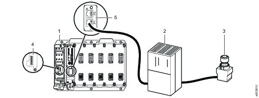
In this mode an external safety PLC controls the e-stop. The safety PLC is connected to a PROFINET fieldbus module on the FlexController. Use an ASM plug on the FlexCarrier.
Pos | |
1 | First FlexCarrier |
2 | Safety PLC |
3 | E-stop |
4 | ASM plug |
5 | PROFINET fieldbus |
Error-Bits reported by the FlexController via PROFIsafe shall not be used to trigger the safety function of a device or system.
GSD-file
Atlas Copco delivers a GSD-file that includes a description of the FlexSystem as an IO device in PROFINET. Use this GSD-file when configuring the PROFINET system.
Logical ports of PROFISafe module
Logical port | Description |
DO1 | Digital Output 1 |
DO2 | Digital Output 2 |
TO1 | Test Output 1. ProfiSafe module to external sensors. |
TO2 | Test Output 2. ProfiSafe module to external sensors. |
DI1 | Digital Input 1 |
DI2 | Digital Input 2 |
DI3 | Digital Input 3 |
DI4 | Digital Input 4 |
DI5 | Digital Input 5 |
DI6 | Digital Input 6 |
Logical illustration - PROFISafe implementation in the FlexSystem

Input process image
The input process image contains the data and status collected from the local digital inputs of the PROFISafe module as well as the PROFIsafe frame elements which are to be transported via PROFINET from the PROFISafe module to the PROFIsafe PLC.
Bit 0 | Bit 1 | Bit 2 | Bit 3 | Bit 4 | Bit 5 | Bit 6 | Bit 7 | |
Byte 0 | DI_1 | DI_2 | DI_3 | DI_4 | DI_5 | DI_6 | Res | Res |
Byte 1 | QDI_1 | QDI_2 | QDI_3 | QDI_4 | QDI_5 | QDI_6 | Res | Res |
Byte 2 | Res | Res | Res | Res | Res | Res | Res | Res |
Byte 3 | PROFIsafe Control Byte | |||||||
Byte 4 | PROFIsafe CRC2 | |||||||
Byte 5 | ||||||||
Byte 6 | ||||||||
The qualifier bits QDI_X indicate whether a fail-safe error was detected at the corresponding input or output channel of the ProfiSafe module. If set to 0, the input or output state is “fail-safe”, that is, the input data contains the fail-safe values or the output is locally set to the fail-safe value by the ProfiSafe module. A qualifier with the value 1 indicates that the input or output is operated without any fail-safe errors.
The input- and output channel qualifiers are operated individually, that is, the qualifiers show the error state only for the corresponding channel or channel group. Other channels may still operate correctly.
Bit | Value | Description |
DI_x | 0 | Input channel inactive (safe state) |
1 | Input channel active | |
QDI_x | 0 | Input channel status “error”, DI_x set to inactive / safe state |
1 | Input channel normal operation. DI_x reflects physical input value | |
QDO_x | 0 | Output channel status “error”. DO_x is set to safe state / inactive |
1 | Output channel normal operation. DO_x can be set/reset via safety fieldbus protocol |
Output process image
The output process image of the PROFISafe module contains all the safety-relevant data sent from the F-Host to the PROFISafe module. The data of the output process image is used on the one hand to control the safe digital output states of the PROFISafe module and on the other hand to send the fail-safe error acknowledge data for the digital inputs and outputs of the PROFISafe module.
Bit 0 | Bit 1 | Bit 2 | Bit 3 | Bit 4 | Bit 5 | Bit 6 | Bit 7 | |
Byte 0 | DO_1 | DO_2 | Res | Res | Res | Res | Res | Res |
Byte 1 | ERDI_1 | ERDI_2 | ERDI_3 | ERDI_4 | ERDI_5 | ERDI_6 | Res | Res |
Byte 2 | ERDO_1 | ERDO_2 | Res | Res | Res | Res | Res | Res |
Byte 3 | PROFIsafe Control Byte | |||||||
Byte 4 | PROFIsafe CRC2 | |||||||
Byte 5 | ||||||||
Byte 6 | ||||||||
Configuration | Dual-Channel | Single-Channel |
DO_1 | Requested value for dual channel output group | Requested value for DO1. |
DO_2 | Unused / Ignored | Requested value for DO2. |
ERDI_1, ERDI_3, ERDI_5 | Error-Reset Bits of the dual channel inputs | Error-Reset Bits of the inputs DI1, DI3, DI5, DI7. |
ERDI_2, ERDI_4, ERDI_6 | Unused / Ignored | Error-Reset Bits of the inputs DI1, DI3, DI5, DI7. |
ERDO_1 | Error-Reset Bits of the dual channel inputs | Error-Reset Bits of the output DO1. |
ERDO_2 | Unused / Ignored | Error-Reset Bits of the output DO2. |
Bit | Value | Description |
DO_x | 0 | Output channel inactive (safe state, low). |
1 | Output channel active (high). | |
ERDI_x | 0 | Input channel error reset not requested. |
1 | Input channel error reset requested. | |
ERDO_x | 0 | Output channel error reset not requested. |
1 | Output channel error reset requested. |


