Introduction
In this section, you can find the basic information about the product and also the formatting conventions used in the topics.
General Description
ToolsTalk 2, the new generation software in controller programming, is ready to take your line management to the next level. The client-server based software solution is geared to provide quick and easy configuration, as well as complete visibility and traceability to your entire line structure. Built on a state-of-the-art user experience and with an extended amount of unique features. Tailored to fit your needs and optimized to get the job done. It allows you to delegate additional features at any time to respective stations, through the embedded simple Functionality Management System (FMS). With 100% customizable user rights, you maintain quality control in complex production systems and increase uptime in production critical operations.
Features
Configuration master of PowerFocus6000, PF6 FlexSystem, accessories, multistep, Fieldbus and Soft plc
Traces analysis and export
Line structure management
Active directory and user administration
Embedded Functionality Management System
Programs library containing full history
Offline and Global programming
Line software visibility and management
Benefits
Reduced training needed due to simple and user friendly interface
Reduced defects with global programs and error notifications
Efficient new product introduction through quick and easy line configuration
Improved productivity due to visibility and traceability on program changes
Increased uptime due to live results analysis and line software management
Full line control thanks to 100% customizable user access permissions
Conventions
To enhance user understanding, certain formatting conventions are used throughout this document. The formatting conventions used are listed below.
Element | Notation | Description | Output |
|---|---|---|---|
General emphasis | In the Program workspace. | To make certain text elements stand out, or to highlight. | Text in Bold |
Graphical User Interface (GUI) items | Select the Function button. | Any reference to items found on screen in the GUI (for example, command buttons, icon names and field names). | Text in Bold |
Graphical User Interface (GUI) Path > | Generally, on the top of the GUI. | Navigation aid which keeps track of the location in the GUI. | For example: Controller > Program > Edit |
User input | Enter a Description for the program. | Any text input by the user. | Text in Bold |
File names | Enter a File Name for the export. | Files either exported from, or imported into the system. | Text in Bold Italic |
Variable and parameter names | Enter a Name for the export. | Variable and parameter names (not values). | Text in Italic |
Variable and parameter values | Enter a VALUE for the export. | Variable and parameter values. | Text in BOLD CAPS |
System output | Client.Domain.Models.ExportImportConfiguration | Any text output by the system. | Text in Monospace |
External links | Links to external sites that have information connected to the document or subject content. These could include:
| Selectable text to external sites | |
Internal documentation links |
If available, these links will be presented below the text. | Selectable text to internal content |
General Data Protection Regulation (GDPR)
This product offers the possibility to process personal identifiable information such as system user name, role and IP-address. The purpose of this processing capability could be to enhance quality control through traceability and proper access management.
If you decide to process personal data you need to be aware of and comply with relevant personal data protection rules, including, in the EU the GDPR as well as other applicable laws, directives and regulations. Atlas Copco can in no way be held liable for any use made by you of the product.
Liabilities and Warnings
Liability
Many events in the operating environment may affect the tightening process and shall require a validation of results. In compliance with applicable standards and/or regulations, we hereby require you to check the installed torque and rotational direction after any event that can influence the tightening result. Examples of such events include but are not limited to:
initial installation of the tooling system
change of part batch, bolt, screw batch, tool, software, configuration or environment
change of air- or electrical connections
change in line ergonomics, process, quality procedures or practices
changing of operator
any other change that influences the result of the tightening process
The check should:
Ensure that the joint conditions have not changed due to events of influence.
Be done after initial installation, maintenance or repair of the equipment.
Occur at least once per shift or at another suitable frequency.
Revision History
Document revision | ToolsTalk 2 Software version | Changes |
|---|---|---|
12.0 | 2.14 |
|
11.0 | 2.13.4 |
|
10.0 | 2.13 |
|
9.0 | 2.12 |
|
8.0 | 2.11 | N/A |
7.0 | 2.9 | N/A |
6.0 | 2.8 | N/A |
5.1 | 2.7.1 | N/A |
5.0 | 2.7 | N/A |
4.0 | 2.6 | N/A |
3.0 | 2.5 | N/A |
2.0 | 2.4 | N/A |
1.0 | 2.3 | First edition |
System Overview
A manufacturing system may consist of the functional blocks in the figure:
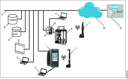
A | Factory network. | H | Controller factory port: connected to the factory network. |
B | ToolsNet server: for storing tightening results and for statistical analysis. | I | Power Focus 6000 controller: used with handheld tools. |
C | ToolsTalk 2 server: for configuration and parameter settings for controllers and IXB tools. | J | Handheld battery tool: uses a wireless connection to the controller. |
D | Industrial PC (IPC): can be used as client terminal to the ToolsTalk 2 and ToolsNet servers. | K | PF6 Flex controller: used with fixtured tools. |
E | Portable computer connected to the factory network: can be used as client terminal to the ToolsTalk 2 and ToolsNet servers. | L | IXB handheld battery tool: uses a wireless connection to the factory network. |
F | Service computer: can be connected to the service port of a controller or an IXB tool. | M | The internet cloud. |
G | Controller service port: can be used to connect a service computer. | N | Atlas Copco Licensing Portal (ACLP): located at Atlas Copco and provides support to licensed functionality in the Functional Management System (FMS). |
Software Structure
Icon | Description |
|---|---|
 | The ToolsTalk 2 system user administration. Selection of language, temperature, controller event notifications and torque units. |
 | The Help icon shows the following:
|
 | Plant Structure Within the plant structure workspace, individual controllers are selected. The workspace is divided into several icons. The menus under each icon are used for configuration of data and parameter settings. The icons differ from the controller interface and the web interface but are very similar in the partitioning and the configurations that can be made under each. |
 | Tightening Program When selected, the workspace shows a list of existing tightening programs. Selecting an individual program opens the different menus to configure and set parameters for the selected tightening program. |
 | Batch Sequence When selected, the workspace shows a list of existing batch sequences. Selecting an individual batch sequence opens the different menus to configure and set parameters for the selected batch sequence. |
 | Sync Mode The icon is only available on controllers with parallel multistep capabilities. The workspace is used to configure and set parameters for all the synchronized multistep tightening programs. |
 | Sources The workspace is used to configure and set parameters for scanners. The workspace is used to configure how identifiers are used to select the next task. |
 | Configurations When selected, the workspace shows a list of existing configurations. The menus where to configure and set parameters vary depending on selected type of device:
|
 | Tools The workspace is used to display which tools are connected to the controller and to see and set tool maintenance intervals and calibration data. |
 | Virtual Stations When selected, the workspace shows a list of existing Virtual Stations. Selecting an individual Virtual Station opens the different menus to configure and set parameters for the following:
|
 | Controller Information Controller hardware and software modules included in the controller. |
 | Fieldbus and SoftPLC The workspace is used to configure the Fieldbus and SoftPLC settings. |
 | Settings
|
 | Results Displays the latest tightening results of a selected controller. Results can be shown in a table format or in graphical trace format. |
 | Events Displays the latest tightening events for a selected controller. Define what events to display in the event configurations in settings |
 | Libraries Includes submenus for managing library templates that can be reused amongst controllers. |
 | Controller Library A library of controller configurations. It is very useful in Station Setup mode which provides a ToolsTalk 2 functionality on a single laptop computer without the need of a server installation. |
 | Program Templates Library This library contains multistep programs saved as templates to use when creating a new multistep program. Editing a multistep program template will not affect multistep programs based on that template. |
 | Tightening Program Library A library of tightening programs. It is possible to copy an existing tightening program to the library. Editing a tightening program in the library will affect all controllers that subscribe to the tightening program. |
 | Configurations Library A library of configurations for Virtual Stations, devices and accessories. It is possible to copy an existing configuration to the library. Editing a library configuration will affect all controllers that subscribe to the configuration. |
 | Fieldbus Library A library of fieldbus configurations. It is possible to copy an existing fieldbus configuration to the library. Editing a fieldbus configuration will affect all controllers that subscribe to the fieldbus configuration. |
 | Settings Library A library for Event configurations that can be distributed to other controllers. The events can be created here or in Settings |
 | System Administration Includes functions for software update, import/export of configuration parameters, program approval, task scheduling and the functionality management system. |
 | Controller Software and Data Management Manages controller software through the ToolsTalk 2 server. |
 | Scheduled Export and Import Schedules repetitive tasks that affect one or many controllers and that are executed by the ToolsTalk 2 server. |
 | Compare Configuration Select configuration files to compare. |
 | User Groups Manages different user groups and the user group rights to folders, controllers and configurations. |
 | Functionality Management System (FMS) Manages licensed controller functionality through the ToolsTalk 2 server. |
 | Program Approval Manages approvals for tightening and loosening programs. |
 | Push The push indicator is shown when configurations have been made to any controller in ToolsTalk 2. Configurations and parameter changes are copied to the controller via the Push function. |
The controller icons differ from the controller GUI and the web GUI but are very similar in the partitioning and the configurations that can be made under each icon.
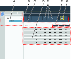
After a successful start of ToolsTalk 2 this view below is displayed, containing the icons described above:

A | Left side menu bar | C | System menu bar |
B | Plant structure workspace | D | Controller workspace |
The controller workspace area displays different content, depending on the selected icon or menu.
Configuration Options
The configuration and setting up of a controller can be done in the following ways:
Controller GUI: This is applicable to Power Focus 6000 controllers which have a touchscreen. A controller can be configured regardless whether it is connected to the network or not.
Web GUI: A PC can be directly connected to the controller service port or if the controller is connected to the network and its IP address is known, it can be accessed from a computer anywhere on the network. One controller at a time can be accessed. For a Power Focus 6000, the web-GUI has the same icons as the controller GUI. For a FlexController, the icons are slightly different. All controllers might have icons that could be unique to them.
ToolsTalk 2 GUI: If the controller is connected to a ToolsTalk 2 server, a ToolsTalk 2 client (PC) can access all connected controllers through the ToolsTalk 2 GUI. Both Power Focus 6000 controllers and FlexControllers can be accessed. The GUI uses a full PC screen and has different partitioning and a different icon, but provides the same functionality.
ToolsTalk 2 GUI in Station Setup mode: Provides a ToolsTalk 2 interface on a PC without a server installation. The PC is connected to the controller service port and provides access to one controller at a time.
License Introduction
Licenses for controller features are managed through the Functionality Management System (FMS). This allows customers to tailor controller functions to their specific needs through a dynamic licensing scheme.
Licenses can be obtained for individual features or collections of features and can be deployed across multiple virtual stations. The licenses can be returned to the pool when they are no longer required. Licenses can be obtained through the Atlas Copco License Portal (ACLP). Licenses can be downloaded from the ACLP and managed/distributed through ToolsTalk, or can be stored on a FMS Portable (USB drive) to be inserted into the controller.
Note that the creation and management of a customer account in the ACLP is not covered in this documentation. Contact your local Atlas Copco representative for more information.
Licenses Overview
Configuration of features governed by licenses can be done even in the absence of an installed license. E.g. configuration of tightening programs and configuration of Multistep programs. Assigning these features to a tool or virtual station is also possible. Running the feature without a valid license, however, will require the installation of the appropriate license.
License enforcement is performed at two stages: assignment and runtime (trigger pressed). If a feature for which no license is installed is assigned to a Virtual Station, a red exclamation mark will appear at the Virtual Station View in ToolsTalk 2. The controller GUI will also show a warning triangle at the tool or task section (depending on what is missing). If a feature for which no license is installed is started (i.e. trigger pressed), an event will be presented to the user informing the user of which license is missing. It will not be possible to proceed without a correct license installed.
Running an unlicensed feature will, in most cases, result in a locked tool.
Many features and functions in the controller require a license in order to be assigned and used by a virtual station. There are three types of licenses:
Virtual Station Type
Fixed collection of features bundled together in a single package. The Virtual Station Type determines, among other things, what tools can be run, how many programs and sequences can be used, which tightening strategies are available, and the type of reporting that can be done. The features contained in each Virtual Station Type are features that often are used in conjunction with each other, or which have internal dependencies that require the presence of other features in the package. Virtual Station Types are assigned in their entirety to a virtual station. The virtual station can then make use of all features contained in the Virtual Station Type. In order to be able to perform tightenings, a Virtual Station has to be assigned a Virtual Station Type license. Depending on the license type, various tightening options will be enabled or blocked.
Virtual Station Feature
Individual features which can complement Virtual Station Types. A lot of features can be purchased as a single license.
Controller Feature
Features that are controller-wide. These are features such as Soft PLC and Step Sync, which are assigned to a controller and once assigned can be used by all virtual stations on that controller.
License Levels
Line Licenser, Line Configurator and Line Manager
These three versions are all client-server based installations of ToolsTalk 2, but with different feature sets. Line Licenser is the smallest package in which ToolsTalk 2 enters on a clean installation, when neither of the other licenses have been installed. When ToolsTalk 2 has the status Line Licenser, all Line Manager and Line Configurator functionality will be visible, but a warning message will appear every time the user tries to use the included features.
ToolsTalk 2 will only remove, unlink, or delete data created in Line Manager, if a downgrade is initiated. This could happen for example when downgrading to a Line Configurator license, or if the trial period of the Line Manager license has expired.
Station Setup
This is a version of ToolsTalk 2 where all the components are located locally on the computer, giving a one-to-one connection. Station Setup runs without an SQL server database connection and has a built-in limit that enables only one connected controller at a time. Note, a valid license is required to use Station Setup, otherwise a warning message will be displayed.
An unlicensed Station Setup can have one virtual station and this will be validated against the License Server.
License Functionality
Symbol | Description |
|---|---|
X | Full functionality. |
X¹ | Connect, disconnect, and restart enabled. |
X² | Push is enabled if changes are made. |
X³ | Custom sections, restart, and right-click functionality enabled. |
X⁴ | Only Database maintenance enabled. |
X⁵ | Read access only, program export enabled. |
Line Licenser | Line Configurator | Station Setup Licensed | Line Manager | |
|---|---|---|---|---|
Plant Structure | ||||
Right-click - Add new controller | X | X | X | X |
Right-click functionality | X¹ | X | X | X |
History on program configuration | X | |||
Tightening Program | X⁵ | X | X | X |
Batch Sequence | X⁵ | X | X | X |
Sources | X⁵ | X | X | X |
Configurations | X⁵ | X | X | X |
Tools | X⁵ | X | X | X |
Virtual Stations | X⁵ | X | X | X |
Controller | X⁵ | X | X | X |
Settings | X⁵ | X | X | X |
Fieldbus | X² | X | X | X |
SoftPLC | X | X | X | |
Results | X | X | X | |
Events | X | X | X | X |
Library | ||||
Tightening Program | X | |||
Configurations | X | |||
Fieldbus | X | |||
Settings | X | |||
Program Templates | X | |||
Controller Configuration | X | X | X | |
System Administration | ||||
Controller Software & Data Management | X³ | X³ | X | |
Scheduled Task | X⁴ | X⁴ | X⁴ | X |
Functionality Management System (FMS) | X | X | X | X |
User Groups | X | |||
Program Approval | X |
Installation and Upgrade
In this section, you can find information to help with the initial installation of the product, or upgrading from one version to another.
Installation Restrictions
Compatibility Matrix
All versions of ToolsTalk 2 software are backwards compatible unless stated otherwise
ToolsTalk2 | PF6 FlexSystem | PF6000 | PF6000 StepSync | Atlas Copco Data Communication Version | IXB | PF8 | PF8 StepSync |
|---|---|---|---|---|---|---|---|
2.3 | N/A | 2.0, 2.1, 2.1.1, 2.3 | N/A | N/A | N/A | N/A | N/A |
2.4 | N/A | 2.4 | N/A | N/A | N/A | N/A | N/A |
2.5 | 1.2 | 2.4 | N/A | N/A | N/A | N/A | N/A |
2.6 | 1.2 | 2.5 | N/A | N/A | N/A | N/A | N/A |
2.7 | 1.3 | 2.6 | N/A | N/A | N/A | N/A | N/A |
2.7.1 | 1.3.1 | 2.6 | N/A | N/A | N/A | N/A | N/A |
2.8 | 1.3.1 | 2.7 | N/A | N/A | N/A | N/A | N/A |
2.9 | 2.0 | 2.7 | N/A | N/A | N/A | N/A | N/A |
2.11 | 2.1 | 2.8 | N/A | N/A | N/A | N/A | N/A |
2.12 | 3.0 | 3.0 | 3.0 | N/A | N/A | N/A | N/A |
2.13 | 3.1 | 3.1.1 | 3.1.1 | 1.7 | N/A | N/A | N/A |
2.14 | 3.3 | 3.3 | 3.3 | 1.9 | 3.3 | N/A | N/A |
ToolsTalk 2 can run with higher versions of Atlas Copco Data Communication. The Atlas Copco Data Communication version mentioned in the matrix is to be considered as the lowest version the ToolsTalk 2 software is compatible with.
Before Installing or Upgrading
It is not recommended to have both a Station Setup and a Client-Server installation on the same computer. Make sure to uninstall and clear the computer from the components of the unwanted installation.
Server Installation
The Microsoft SQL database, the ToolsTalk 2 server application and the ToolsTalk 2 client application, can all be installed on the same computer.
Before starting the installation, make sure the following is available:
Administrator rights to the computer upon which the server application is to be installed.
Administrator rights to the computer upon which the client application is to be installed.
Computers and programs according to the listed prerequisites.
A completed installation of the 64-bit Microsoft SQL database according to the listed prerequisites.
An executable file for the server application.
An executable file for the client application.
Atlas Copco Data Communication (ACDC) is installed and running and is compatible with the current version of the ToolsTalk 2 (only for versions of ToolsTalk 2 from 2.13 onwards). Please see the Atlas Copco Data Communication Installation User Guide.
Station Setup
Before starting the installation, make sure the following is available:
Administrator rights to the computer upon which the application is to be installed.
Computers and programs according to the listed prerequisites.
An executable file for the Station Setup application.
Database Requirements
All controller data and configurations are stored in the database catalog. The database is a standard 64-bit Microsoft SQL database.
The installation of a Microsoft SQL database is not described in this document. It is recommended to follow a standard installation.
The Microsoft SQL database may be located on the same server or the same network as the ToolsTalk 2 application.
If the database is located elsewhere, firewall needs to be properly configured between the database and the ToolsTalk 2 application server.
The IP address of the Atlas Copco Data Communication server must be known and entered into every controller that is connected to ToolsTalk 2
The server address that hosts the ToolsTalk 2 application must be known by the client PC if a remote connection is being used.
Mandatory when installing the Microsoft SQL database
64-bit Microsoft SQL.
Select both Microsoft SQL server authentication and windows authentication.
Recommended when installing the Microsoft SQL database
Include the management studio in the installation.
Enable the default instances.
Computer Requirements
The ToolsTalk 2 ecosystem requires the following functions to be in place:
64-bit is required for client, server, Station Setup and ClickOnce.
Area | Category | Minimum Requirement | ToolsTalk 2 Release Version | Comments |
|---|---|---|---|---|
Server software requirements | Database | SQL Server 2014 R2, or later version SQL express 2014 R2, or later version (Compatible but not recommended) | The database can be located locally on the same machine, or installed on a remote database server. | |
Java | Version 8 or later | ≥2.3 | 64-bit version | |
.NET Framework | Version 4.6 | 2.3 - 2.4 | ||
Version 4.6.2 | 2.5 - 2.12 | |||
Version 4.8 | 2.13 - current version | |||
Server hardware requirements | Processor | Dual Core 2.70 GHz Intel Xenon or higher | This specification is only meant to give an indication of the performance needed. | |
Memory (RAM) | 4 GB | This specification is only meant to give an indication of the performance needed. | ||
Disk space | 50 GB | Note that the database will grow over time. Configurations and configuration changes are stored to the database. More controllers will also add more info to the database. | ||
Disk speed | 5400 rpm or higher | |||
PC client requirements | Operating system | Windows 10 Windows 7 | 2.14 2.3 - 2.13 | ToolsTalk 2 version 2.14 does not support Windows 7! |
.NET Framework | Version 4.6 | 2.3 - 2.4 | ||
Version 4.6.2 | ≥2.5 - 2.12 | |||
Version 4.8 | 2.13 - current version | |||
User rights | Database access | System administrator access or similar | Users performing the installation, must also have admin rights to create users in the database. | |
Windows access | Administrator account | Needed in order to install the application and its dependencies. |
License Requirements
An Atlas Copco license server is needed when the Functional Management System (FMS) is being used for licensed Feature items.
The license server is included in the server installation file. For correct installation the JAVA_HOME system variable must have a correct path and point at the 64-bit Java installation.
The FMS can only be used in a client-server installation and is not applicable in a Station Setup installation.
Installation Sequence
The installation sequence for any of the ToolsTalk 2 applications should be as follows:
Make sure all the computer and database requirements are met before installation.
Install the Microsoft SQL server.

Refer to https://docs.microsoft.com/en-us/sql/database-engine/install-windows/install-sql-server?view=sql-server-ver15 for the correct installation procedures.
Install Atlas Copco Data Communication if applicable.
Refer to the Atlas Copco Data Communication Installation guide for further information.
Install the required ToolsTalk 2 application.
Deploy the ToolsTalk 2 application if installing the ToolsTalk 2 client application or run the application from the start menu and create shortcuts if required.
License the ToolsTalk 2 application so you get the right features you subscribed to.
Software Installation
ToolsTalk2 Configuration Window
With the ToolsTalk 2 configuration, it is possible to finish the installation of the ToolsTalk 2 software first and then configure the different installation parameters. The ToolsTalk 2 configuration for each installation type is available as a shortcut in the start menu after the installation and so it can be accessed anytime to make changes to the installation parameters.
Default Installation Locations
Installation | Default Location | Remarks |
|---|---|---|
ToolsTalk 2 Server | C:\Program Files (x86)\Atlas Copco\ToolsTalk Server\ | Can be changed to a desired location by the user |
ToolsTalk 2 ClickOnce | C:\Program Files (x86)\Atlas Copco\ToolsTalk ClickOnce\ | Can be changed to a desired location by the user |
ToolsTalk 2 Client | C:\Program Files (x86)\Atlas Copco\ToolsTalk Client\ | Can be changed to a desired location by the user |
ToolsTalk 2 StationSetup | C:\Program Files (x86)\Atlas Copco\ToolsTalk StationSetup\ | Can be changed to a desired location by the user |
AtlasCopco FMS | C:\ProgramData\AtlasCopcoFMS\ | The default path should not be changed! |
Flexera Logs | C:\Windows\ServiceProfiles\NetworkService\Flexnetls\acopco\logs | The default path should not be changed! |
Installing the ToolsTalk Server Application
Before you begin with the ToolsTalk 2 server installation, make sure all the requirements are met as described in section Before Installing or Upgrading.
Before installing the Server Application, make sure that the Atlas Copco Data Communication (ACDC) installed and running is compatible with the current version of the ToolsTalk 2 (only for versions of ToolsTalk 2 from 2.13 onwards). Please see the Atlas Copco Data Communication Installation User Guide.
Place the executable file ToolsTalkServer<xxx>.exe in a desired folder on your computer. The <xxx> represents the version of the file.
Double-click on the executable file.
Select Yes to Do you want to allow this app to make changes to your device?
Select Next in the Atlas Copco Tools Talk Server - InstallShield Wizard window to continue.
Read and then select I accept the terms in the license agreement. Select Next to continue.
Select Print if you would like to print the license agreement.
Select Change... to install the application in a different location. The default location is C:\Program Files (x86)\Atlas Copco\ToolsTalk Server\
Select Next to continue.
Select Install to finish the installation.
Select Finish to complete the installation and the ToolsTalk 2 Configuration window opens up or the User Access Control dialog from Windows may be prompted.
If Windows prompts the User Access Control dialog requesting permission, Select Yes to Do you want to allow this app to make changes to your device?
When the installation is completed, the ToolsTalk 2 Configuration window opens up.
If you select No, then the ToolsTalk2 Configuration window does not open automatically and you need to access it from the Windows Start Menu. If the ToolsTalk 2 configurator is opened from the Windows Start menu, select Force Initialize at the bottom of the ToolsTalk 2 Configuration window to complete the installation procedure.
If an error occurs during installation, a step is unclear, or a parameter name or value is unclear, look for more information in the Troubleshooting section.
Enter the parameters in the Server Settings.
Selecting Save will save the Server Settings and will try to restart the service.
if you select Save before entering and completing the Database Installation Settings, an error Changes accepted, but failed to control dependent Windows service appears.
Go to Database Installation Settings and enter the User name and Password and select Test Connection to test the database connection.
The User name and Password should be the same as used for the Microsoft SQL Server installation.
Select Install Database.
Upon successful installation of the database, the message Database creation succeed is displayed.
Select Save and Close.
If you receive a notification about Dependent service not started, restart the FNLS-acopco service and restart the ToolsTalk 2 configuration again. When both the services are up and running, continue with the installation.
Server Settings Parameters
Parameters | Description |
|---|---|
SQL Server Address | IP or Hostname of the SQL Server The Microsoft Windows Defender Firewall will prevent connections through the network to SQL Server. Therefore, it is required to configure SQL Server to accept connections by using TCP/IP. This setting can be modified in section SQL Server Configuration Manager in Windows Computer Management. Computer Management -> SQL Server Configuration Manager -> SQL Server Network Configuration -> Protocols for MSSQLSERVER -> TCP/IP -> Enabled |
Database Name | The Database/Catalog used by ToolsTalk 2. The database will be created during database installation if not already existing. |
Parameters | Description |
|---|---|
Authentication Mode | The authentication mode used to verify user authority. Select Windows (Active directory) or None. |
Active Directory Group | Only visible if the Authentication Mode selected is Windows. Specifies what active directory group a user must be member of. Example: DOMAIN\GROUP |
Server Address | IP or Hostname of the ToolsTalk 2 Server. |
Web Application Port | Communication port for ToolsTalk 2. |
Controller Port | Port 9016 is used as the default controller port. If using the port 9016, make sure this port is open and you can connect to it, else the application will not work. Port 80 is used when the function Connect/disconnect/add controller is used from ToolsTalk 2 to interact with a controller. |
Make sure that the controller port you enter is open and is possible to connect to!
Parameters | Description |
|---|---|
Controller Backup Folder | Specifies a folder where the backup for the controllers will be located. |
Parameters | Description |
|---|---|
Server Address | IP or Hostname of the Atlas Copco Data Communication server |
Web API Port | Port for Web API |
SignalR Port | Port for SignalR |
Database Installation Settings
Parameters | Description |
|---|---|
User name | The username of a database user with the credentials to create databases/catalogs. Usually the system administrator credential. |
Password | Enter the password. Usually the system administrator credential |
Parameters | Description |
|---|---|
Manual Script | Specifies whether or not the database has been manually created. If this box is checked, ToolsTalk 2 expects that you have already created the SQL catalogue and the default user manually. The entered User Name and Password will be the default credentials that connects to the SQL server and are stored in clear text in the configuration files. This setting should be only used if you have created the database catalogue and user yourself. |
The ToolsTalk 2 application is available in the start menu.
Installing the Client Application
Before you begin with the ToolsTalk 2 client installation, make sure all the requirements are met as described in section Before Installing or Upgrading.
Place the executable file ToolsTalkClientxxx>.exe in a desired folder on your computer. The <xxx> represents the version of the file.
Double-click on the executable file.
Select Yes to Do you want to allow this app to make changes to your device?
Select Yes in the Atlas Copco Tools Talk Server - InstallShield Wizard window to continue.
Read and then select I accept the terms in the license agreement. Select Next to continue.
Select Print if you would like to print the license agreement.
Select Change... to install the application in a different location. The default location is C:\Program Files (x86)\Atlas Copco\ToolsTalk Client\
Select Next to continue.
Select Install to finish the installation.
Select Finish to complete the installation.
If an error occurs during installation, a step is unclear, or a parameter name or value is unclear, look for more information in the Troubleshooting section.
When the installation is completed, the ToolsTalk 2 Configuration window opens up.
Enter the parameters in the Client Settings and select Save.
Server Settings Parameters
Description
Authentication Mode
The authentication mode used to verify user authority. Select Windows (Active directory) or None.
Server Address
IP or Hostname of the ToolsTalk 2 Server.
Web Application Port
Communication port for ToolsTalk 2.
Convert Service URL to IP Address
On or Off. When On is selected, if a hostname is used in the address, it is converted to an IP address.
The ToolsTalk 2 application is installed and a shortcut available on the desktop.
Installing the Client by Using ClickOnce
Place the executable file ToolsTalkServerClickOnce<xxx>.exe in a desired folder on your computer. The <xxx> represents the version of the file.
Double-click on the executable file.
Select Yes to Do you want to allow this app to make changes to your device?
Select Next in the Atlas Copco Tools Talk Server ClickOnce - InstallShield Wizard window to continue.
Read and then select I accept the terms in the license agreement. Select Next to continue.
Select Print if you would like to print the license agreement.
Select Change... to install the application in a different location. The default location is C:\Program Files (x86)\Atlas Copco\ToolsTalk ClickOnce\
Select Next to continue.
Select Install to finish the installation.
Select Finish to complete the installation and the ToolsTalk 2 Configuration window opens up or the User Access Control dialog from Windows may be prompted.
If Windows prompts the User Access Control dialog requesting permission, Select Yes to Do you want to allow this app to make changes to your device?
When the installation is completed, the ToolsTalk 2 Configuration window opens up.
If you select No, then the ToolsTalk 2 Configuration window does not open automatically and you need to access it from the Windows Start Menu. If the ToolsTalk 2 configurator is opened from the Windows Start menu, select Force Initialize at the bottom of the ToolsTalk 2 Configuration window to complete the installation procedure.
If an error occurs during installation, a step is unclear, or a parameter name or value is unclear, look for more information in the Troubleshooting section.
Enter the parameters in the Server Settings.
Selecting Save will save the Server Settings and will try to restart the service.
if you select Save before entering and completing the Database Installation Settings, an error Changes accepted, but failed to control dependent Windows service appears.
Go to Database Installation Settings and enter the User name and Password and select Test Connection to test the database connection.
The User name and Password should be the same as used for the Microsoft SQL Server installation.
Select Install Database.
Upon successful installation of the database, the message Database creation succeed is displayed.
Select Save and Close.
If you receive a notification about Dependent service not started, restart the FNLS-acopco service and restart theToolsTalk 2 configuration again. When both the services are up and running, continue with the installation.
Server Settings Parameters
Parameters | Description |
|---|---|
SQL Server Address | IP or Hostname of the SQL Server The Microsoft Windows Defender Firewall will prevent connections through the network to SQL Server. Therefore, it is required to configure SQL Server to accept connections by using TCP/IP. This setting can be modified in section SQL Server Configuration Manager in Windows Computer Management. Computer Management -> SQL Server Configuration Manager -> SQL Server Network Configuration -> Protocols for MSSQLSERVER -> TCP/IP -> Enabled |
Database Name | The Database/Catalog used by ToolsTalk 2. The database will be created during database installation if not already existing. |
Parameters | Description |
|---|---|
Authentication Mode | The authentication mode used to verify user authority. Select Windows (Active directory) or None. |
Active Directory Group | Only visible if the Authentication Mode selected is Windows. Specifies what active directory group a user must be member of. Example: DOMAIN\GROUP |
Server Address | IP or Hostname of the ToolsTalk 2 Server. |
Web Application Port | Communication port for ToolsTalk 2. |
Controller Port | Port 9016 is used as the default controller port. If using the port 9016, make sure this port is open and you can connect to it, else the application will not work. Port 80 is used when the function Connect/disconnect/add controller is used from ToolsTalk 2 to interact with a controller. |
Convert Service URL to IP Address | On or Off. When On is selected, if a hostname is used in the address, it is converted to an IP address. |
Make sure that the controller port you enter is open and is possible to connect to!
Parameters | Description |
|---|---|
Controller Backup Folder | Specifies a folder where the backup for the controllers will be located. |
The Active Directory Group and Controller Backup Folder are empty by default.
Parameters | Description |
|---|---|
Server Address | IP or Hostname of the Atlas Copco Data Communication server |
Web API Port | Port for Web API |
SignaIR Port | Port for SignaIR |
Database Installation Settings
Parameters | Description |
|---|---|
User name | The username of a database user with the credentials to create databases/catalogs. Usually the system administrator credential. |
Password | Enter the password. Usually the system administrator credential |
Parameters | Description |
|---|---|
Manual Script | Specifies whether or not the database has been manually created. If this box is checked, ToolsTalk 2 expects that you have already created the SQL catalogue and the default user manually. The entered User Name and Password will be the default credentials that connects to the SQL server and are stored in clear text in the configuration files. This setting should be only used if you have created the database catalogue and user yourself. |
Deploying the Client On a Remote Machine
Browse to the server, via web browser, by using the link:
http://<FULL COMPUTER NAME>:<PORT NUMBER>/deploym

Replace <FULL COMPUTER NAME> and <PORT NUMBER>.
Make sure that the <FULL COMPUTER NAME> is exactly the same as on which the server and database are located. If Full Computer Name [TOOLSE277256.ATLASCOPCO.COM] or Computer Name [TOOLSE277256] is set, then a DNS server must exist and be set in the controller, otherwise it is not possible to add controllers to the ToolsTalk 2 environment.
Save the executable file ToolsTalk.Client.WPF.Desktop.application on your computer.
Double-click on the executable file, or select Open if prompted.
ToolsTalk 2 client opens with the latest version installed.
The ToolsTalk 2 client will always open with the latest server version by using ClickOnce.
Deploying the Client on Local Machine
If ClickOnce was installed in the default folder, navigate to “C:\Program Files (x86)\Atlas Copco\ToolsTalk ClickOnce\ClientDeploy” and double click on ToolsTalk.Client.WPF.Desktop Application manifest file to deploy the client.
Once the installation is completed, the ToolsTalk 2 icon is created on the desktop.
Installing the Station Setup Application
The condensed Station Setup installation has full controller configuration functionality, but also some limitations:
The entire installation has a smaller footprint and is installed on a portable computer.
Only one physical controller can be managed at a time.
The computer is connected to the service port of the controller to avoid interruption of normal activity.
Applications
The typical application for this mode of operation can be the following:
A controller can be accessed using ToolsTalk 2 without connecting to the customer network but instead using the service port of the controller.
Offline configuration of controllers using the controller library features. The configuration file can later be transferred to a real controller for verification.
An easy export of a controller configuration that is very helpful in debugging tasks.
Before you begin with the ToolsTalk 2 Station Setup installation, make sure all the requirements are met as described in section Before installing or Upgrading.
Place the executable file ToolsTalkStationSetup<xxx>.exe in a desired folder on your computer. The <xxx> represents the version of the file.
Double-click on the executable file.
Select Yes to Do you want to allow this app to make changes to your device?
Select Next in the Atlas Copco Tools Talk Server - InstallShield Wizard window to continue.
Read and then select I accept the terms in the license agreement. Select Next to continue.
Select Print if you would like to print the license agreement.
Select Change... to install the application in a different location. The default location is C:\Program Files (x86)\Atlas Copco\ToolsTalk StationSetup\
Select Next to continue.
Select Install to finish the installation.
Select Finish to complete the installation.
If an error occurs during installation, a step is unclear, or a parameter name or value is unclear, look for more information in the Troubleshooting section.
When the installation is completed, the ToolsTalk 2 Configuration window opens up.
Enter the parameters in the Server Settings tab and select Save.
Parameters | Description |
|---|---|
ToolsTalk User Name | Username of the user that is local to the application. |
Server Address | IP or Hostname of the ToolsTalk 2 Server. |
Web Application Port | Communication port for ToolsTalk 2. |
Parameters | Description |
|---|---|
Web API | Web API port |
SignalR | SignalR port |
Controller Port | Port 9016 is used as the default controller port. If using the port 9016, make sure this port is open and you can connect to it, else the application will not work. Port 80 is used when the function Connect/disconnect/add controller is used from ToolsTalk 2 to interact with a controller. |
Make sure that the controller port you enter is open and is possible to connect to!
The ToolsTalk 2 application is available in the start menu.
Station Setup Connection
A computer with a Station Setup of ToolsTalk 2 can be connected to a controller through the network or directly to the service port.
Network Connection
The ToolsTalk 2 server connection address in the controller must be directed to this computer. This is done via the controller GUI or the controller web GUI.
Only one controller at a time can be connected to a computer with a ToolsTalk 2 Station Setup. If an online controller is connected to the ToolsTalk 2 Station Setup computer, subsequent connection attempts from other controllers will be ignored.
Controller Service Port Connection
The controller service port can be used to connect a controller to ToolsTalk 2 when the PC with ToolsTalk 2 is not allowed to be connected to the network. For example, an Atlas Copco - or external - service technician visits a factory and the external computer is not allowed to be connected to the factory network.
If a computer is connected to the service port of the controller, the controller acts as a DHCP server and provides an IP address to the computer. This address must be entered in the controller server connection address field for the ToolsTalk 2 connection.
File Comparison
The configurator stores a copy of all configuration settings as an .xml file called Storage. The file helps in identifying manual changes in the product configuration .xml files. If the product configuration .xml files have been modified, then when you start the configurator, the File Comparison window opens, where you can choose between options Use Storage Files or Use Configuration Files.
SoftPLC Configurator Installation
To be able to use the SoftPLC functionality in a controller, the SoftPLC Configurator must be installed on the computer where a ToolsTalk 2 Client is installed.
Insert a USB device or similar, containing the MultiProg551_Atlas_Installation.
Double-click on Installation.bat in MultiProg551_Atlas_Installation, the installation starts.
Open the ToolsTalk client when the installation is completed (no restart required).
In the ToolsTalk 2 client, go to the Fieldbus and SoftPLC
 tab. Select the SoftPLC configuration section and in the General SoftPLC Settings, set SoftPLC to On.
Uninstalling the Software
Each one of the modules (Client, Server, Station Setup) can be uninstalled as follows:
Using the windows control panel / Programs and features to select and uninstall the desired programs and modules.
For some modules it may be necessary to restart the computer for the changes to take effect.
Installation Validation
Validating Windows System Services
To verify that background programs and services have started correctly, perform the following check:
Select the Windows Search button.
Type services in the Search windows entry box.
Scroll down and verify that the Atlas Copco Industrial Technique Host for ToolsTalk has started.
This indicates that the ToolsTalk 2 server application is running.
Scroll down and verify that the FlexNet License server - acopco has started.
This indicates that the license server application for the functional management system is running.
Validating the Client-Server Installation
After successful installation of the client-server version of the ToolsTalk 2 application, a controller is needed for a complete system test.
The server computer must be connected to the network.
The client computer must be connected to the network.
The controller must be connected to the network and configured to communicate with the server computer.
Check that Atlas Copco Data Communication service is started.
The server and client may be installed on the same computer.
For configuration and starting the controller please refer to the controller user guide.
For configuration, starting and navigating in the ToolsTalk 2 GUI, please refer to the ToolsTalk 2 user guide.
If the ToolsTalk 2 client is installed, the application can be started in the following way:
Select the Windows Start menu and locate the ToolsTalk 2 folder.
Select the ToolsTalk 2 icon
 to launch the application.
Validating the Station Setup Installation
If the ToolsTalk 2 Station Setup is installed, the application can be started in the following way:
Select the Windows Start menu and locate the ToolsTalk 2 folder.
Select the ToolsTalk 2 icon
to launch the application.
The ToolsTalk 2 Station Setup application cannot execute if a ToolsTalk 2 client application or a ToolsTalk 2 server application is installed. They can easily be removed by executing their respective installation programs and choose the Remove option in the Program maintenance window.
The Getting started section in the ToolsTalk 2 user guide describes the windows and the window navigation.
The GUI for a ToolsTalk 2 Station Setup application is slightly different if there is no controller connected. Please refer to the information under the library  icon and the controller library
  icon in the configuration manual.
Validating the License Service
This validation process is only applicable for Client, Server and ClickOnce application installations and is not valid for a Station Setup installation.
When the ToolsTalk 2 installation is complete, you will need to check that the license service is ready upon startup.
Open a web browser, browse to the following two pages and complete the steps:
http://”ip-address:port"/api/1.0/health - This page should have the “connectionCheck” : “success”, if not you will need to restart the Flexera service. In some cases more than one restart may be required.
http://”ip-address:port"/api/1.0/hostids - If this page is empty you will need to restart the Flexera service. In some cases more than one restart may be required.
This validation process is not applicable for a Station Setup installation
Upgrading ToolsTalk 2
Please make sure that the ToolsTalk2 server is running before starting the upgrade.
When upgrading ToolsTalk 2 from 2.12 or earlier versions and Atlas Copco Data Communication (ACDC) is already installed, make sure that the controller port is pointing to the same port that ACDC was installed on. If you are installing ACDC for the first time and want to use another port than your current controller port in your ToolsTalk 2 version, then please change the controller port as described in the following procedure.
In the configuration files, controller port is named as HubPort.
In ToolsTalk.Server.SelfHostService.exe.config(ClickOnce/Client/Server) or ToolsTalk.Standalone.exe.config(Station Setup), change the controller port to the correct port number <add key="HubPort" value="XXXX" />
Troubleshooting
Troubleshooting During Installation
Restart the ToolsTalk Industrial Technique Host service after upgrading ToolsTalk 2.
Error | Solution |
|---|---|
Error code 1920 Failed to start. Verify you have correct permission | Database authentication error. For the SQL database mixed mode authentication must be configured. Use the SQL management studio to correct the authentication. A restart of the computer is most likely needed before another installation attempt can be made. |
The InstallShield Wizard detects if installations have already been made, when using an installation file. If older installations are present on the computer, they may not be detected.
It is therefore recommended to remove old instances of the program and of the database catalog before starting a new installation.
Configuration
In this section, you can find detailed information about how to create, modify, and verify product settings.
- Getting started
- Quality Integrated Fastening Accessories (QIF)
- Working with the Batch Sequence Tab
- Working with the Configurations Tab
- Working with the Controller Information Tab
- Working with the Fieldbus and SoftPLC Tab
- Working with the Libraries Tab
- Working with Push Configuration Changes
- Working with the Settings Tab
- Working with the Sources Tab
- Working with the StepSync System
- Working with the System Administration Tab
- Working with the Tightening Program Tab
- Working with the Tools Tab
- Working with the Virtual Station Tab
Getting started
Starting
If the ToolsTalk 2 client is installed, the application can be started:
Select the Windows Start menu, open All programs and scroll down to ToolsTalk 2.
Open the folder and select ToolsTalk 2
to launch the application.
Controllers
Controller Types
Apart from the controllers that are supported and configurable using ToolsTalk 2, there is the capability to show other controller types in the Controller List and some limited information about these. The controllers which aren't configurable can launch the relevant software through ToolsTalk 2, where they can be further configured.
The different controller types are represented with an icon in the All Controllers list.
Controller Icon | Controller Type | Compatible Software |
|---|---|---|
| Power Focus 6000 | ToolsTalk 2 |
| PF6 Flex System | ToolsTalk 2 |
| Power Focus 6000 StepSync | ToolsTalk 2 |
| Power Focus 4000 | ToolsTalkPF |
| Power Macs 4000 | ToolsTalkPM |
| Unsupported Controller - A Controller with a higher version and not compatible with the current ToolsTalk 2 release | N/A |
| IXB | ToolsTalk 2 |


Controller Information
The following is an example of the information that a Power Focus 4000, or a Power Macs 4000 controller can display. An Unsupported Controller will not display this information..
Application Boot Software Version
Controller Serial Number
Protocol Version
RBU Serial Number
RBU Type
Software version
Tool Information
The information below is displayed under Tools in ToolsTalk 2. What will be shown here is configured in the respective controller software.
Identifier
Serial Number
Model Type
Service Date
Calibration Date
Tightening Count
Tool Type
Tightenings Since Service
Application Code Version
Boot Code Version
To receive tool information, the controllers will need to be connected to ACDC. For further information please see the ToolsTalk 2 documentation.
Adding Controllers
Controllers connected to ToolsTalk 2 may be visible in the Plant structure
 .
.
The plant structure view is empty if no controllers are connected to ToolsTalk 2, or if user rights do not allow access to folders or controllers.
Select Plant structure and then right-click anywhere in the upper area of the controller list. Alternatively, select System administration, then in the Controller software & data management tab right-click in the left-side menu workspace area. Choose Add new controller. The Connect controller dialog window opens.
Enter the IP address, or the DNS name of the controller. The IP address of the ToolsTalk 2 server will be pre-populated.
Select Connect and select Close once the Controller online message is displayed.
Connection Status
If you enter the IP address of an already connected controller in the Connect controller window, the message Controller already connected and online is displayed.
The message Waiting for controller to come online is displayed while the connection is being established.
The message Controller online is displayed when the connection to the controller is established.
The message ToolsTalk failed to connect to controller. Please verify IP address/DNS name is displayed if the connection failed.
A controller can also be connected to the ToolsTalk 2 application via the web GUI or controller GUI.
This procedure is described in the controller specific documentation.
Managing the Controller List
The Plant structure workspace default view displays All controllers. The All controllers view contains all the controllers currently connected to the ToolsTalk 2 server, regardless of whether they are online or offline. Custom Sections is a subsection of All Controllers ordered into folders.
Selecting a Custom Sections folder
On the top of the controller list, click the options button,  and select Custom Sections and then select the appropriate folder.
Selecting a Controller
In the left side menu bar, select Plant structure
.Scroll down to the relevant controller and select it by clicking on the name field
 .
. The selected controller is highlighted. A controller with an online status constantly updates the ToolsTalk 2 application.
Offline controller names are struck-through.
A controller in offline status may display old and outdated information if changes have been made through another controller interface other than ToolsTalk 2.
It is possible for several ToolsTalk 2 users to access the same controller. If an attempt is made to select a controller, which is already selected by another ToolsTalk 2 user, a modal dialog box is displayed with the following warning message:
Other users are currently active in the system. Parameter values may be changed without notice.
Select OK to close the dialog box and to continue.
Searching for Controllers
In the Plant structure workspace there is a field for searching for controllers in the controller list.
In the search field, enter at least two letters of the controller name.
It is possible to search for the controller name or type.
Remote Controller Restart
In certain circumstances it may be required to make a complete power on reset (POR) of the controller.
The following describes how to make a remote POR from ToolsTalk 2:
In the left side menu bar, select Plant structure
.Right-click on the selected controller and select Restart in the shortcut menu
Confirm or cancel the controller restart operation in the modal window dialog. The controller will first go offline before it gets back online.
This operation may take a few minutes.
While this is in progress, it is possible to perform other tasks in ToolsTalk 2.
It is only possible to make a remote restart on a controller that is online and connected to the ToolsTalk 2 application server. Offline controller names are struck-through.
Saving Changes in Parameters and Configurations
When a controller has a status of On-line, it automatically updates ToolsTalk 2 if any changes are made in the web GUI or in the controller GUI.
Any changes made in ToolsTalk 2 are automatically saved but are not copied to the controller. A Push copies changes to the controller and is executed by an active command.
A push indicator  is displayed beside the controller name in the plant structure workspace to indicate that configuration changes have been made in ToolsTalk 2 but not yet copied to the controller.
A push can be made in several ways:
Select the Push indicator icon
next to the controller name in the controller list.Click the Push command button
 in the system menu bar to start copying changes from ToolsTalk 2 to one or more controllers. A shortcut menu opens to select affected controllers
Right click on a controller name in the plant structure
workspace and select the Push command button in the shortcut menu. Changes are copied from ToolsTalk 2 to the one selected controller.
It is not possible to make a Push to a controller which has a status of Off-line.
Managing the Workspace Windows
The workspace for plant structure and reports both involve the selection of a single controller for further work. The workspace can be minimized or maximized to increase the space for the controller workspace by either, dragging as described and shown in the image below, or by selecting the Plant structure icon .
Minimizing and Maximizing the Workspace View
Place the cursor on the line between the two workspace areas. The cursor shape changes from a white arrow to the shape of a horizontal double sided arrow.
Click-hold-drag and the border line between the two workspace area can be moved. The workspace can be maximized by moving the window border all the way to the left-side menu, or maximized by moving the window border to the right-side menu.
Filtering and Sorting the Data Grid
The data grid columns in the workspace windows can be sorted and filtered.
Select a column header to access the sort and filter function.
To sort the list, select Sort list to arrange the list into ascending, descending, or default order.
To filter the list, select the check boxes to filter what is to be displayed. Select Clear filter to return to the default view.
User Interface - Workspace With Controller Overview
After selecting a controller and selecting a controller menu icon, the controller workspace can show the following information.
A | A selected controller in the Plant structure workspace |
B | Controller name in the controller workspace. The name is identical to the selected controller name in the Plant structure |
C | Name of the selected controller menu icon |
D | List of configurations with overview information in the controller workspace |
E | Controller menu icons |
F | A row of command buttons in the controller workspace. The type of command buttons vary depending on the controller menu icon selected |
G | Selected controller menu icon. Highlighted with a yellow border |
The workspace overview shows either a list of configurations or shows menus with parameter values. If a list of configurations is shown, the next level, the Menu level is accessed by a double-click on a configuration name.
Quality Integrated Fastening Accessories (QIF)
The QIF (Quality Integrated Fastening) is a series of accessories used for communication between a controller and operator. The configuration of QIF accessories is available in the Configurations section  .
.
Working with the Batch Sequence Tab
A Batch Sequence task is selected in a Virtual Station Task configuration, or by an external input source.
The tightening order can either follow a fixed scheme, or be left to the operator to decide in a free-order scheme. In either case, the sockets or signals can be used to communicate between the controller and the operator.
A Batch consists of one tightening program, which is repeated a number of times.
A Batch Sequence is an ordered set of batches, when the operation requires a combination of batches/tightening programs.
Select a controller in the Plant structure
. Go to Batch Sequence
 .
.
The columns contain the following information:
Column | Description |
|---|---|
Name | Each Batch Sequence name starts with an index number. The following characters can be changed to any user defined name. |
Last changed | Expressed in ToolsTalk 2 time. |
Last changed by | Configuration data last changed by <user>. |
Controller updated | Expressed in controller time. |
Controller updated by | Controller updated by <user>. |
The field Changed by and Controller updated by can be a registered ToolsTalk 2 user, created in the ToolsTalk 2 interface.
Command | Description |
|---|---|
Manage |
The list of configurations will show irregularities in the index number scheme when a configuration is deleted. Index numbers do not change. Adding a new configuration will attempt to find the lowest free index position for a configuration. |
Add | Create or Import a new Batch Sequence. |
The Batch Sequence name consists of an index number combined with optional characters. The index position cannot be changed. A new configuration is given lowest possible available index number. The index number is important when using sources and identifier numbers to be part of the task selection process.
Batch Sequence Configuration Workspace
The Batch Sequence configuration workspace shows the details of a single batch sequence with the following configuration menus:
Basic settings, with configuration name and description.
General settings, controlling the flow and order of tightenings.
Sequence configuration, creates the batch sequence from individual tightening programs.
Select a controller in the Plant Structure workspace
.Select Batch Sequence
in the menu bar.Double-click on the Name of the desired batch sequence to display the menus.
Batch Sequence Configuration Menu
The options in the Properties menu are as follows:
Parameter name | Description |
|---|---|
Name | Default name Batch sequence. This can be edited. |
Description | The optional description issued for the batch sequence. |
Lock tool on batch sequence complete | On: The tool is locked when the batch sequence is completed. Off: The tool remains unlocked when the batch sequence is completed. |
Free order | No: The batches within the sequence are executed in the order listed by the index number. If sockets have been specified, the system will prompt for the next socket when the batch is to be performed. Yes: The tightenings and the batches within the sequence can be executed in any order. The operator must indicate to the system which batch is to be executed by using the Socket selector bits, these act as identifier numbers. |
Increment on NOK | No: The batch counter is not incremented if the tightening fails (NOK). Yes: The batch counter is incremented if the tightening fails (NOK). |
Max consecutive NOK | Max consecutive NOK is defined as the maximum allowed number of consecutive failed tightenings in a batch. If the value is reached, the event Too many NOK tightenings (4020) is displayed. |
Decrement on loosening | Never: The batch counter is not decremented when a loosening is performed. This is the default value. Always: The batch counter is decremented when a loosening is performed. When last tightening OK: If the preceding tightening was OK, the batch counter is decremented when a loosening is performed. |
Sequence abort time | On: The selected batch sequence will be aborted within a specified time limit. When you select On, the Abort time field opens. Off: The selected batch sequence cannot be aborted. |
Abort time | The number of seconds during which the selected batch sequence will be aborted. Allowed range is between 1 s to 1600 s. |
A batch sequence is completed (and the tool may be locked) when either:
All tightenings have been completed with an OK or NOK result.
The Abort sequence signal terminates the task. Unperformed tightenings are reported with NOK result.
In the Sequence configuration menu, the different batches are combined into a batch sequence. A batch consists of one single tightening program that is repeated a number of times.
Each row in the Sequence configuration menu represents one single batch.
Column | Description |
|---|---|
Check box. | |
Batch | Batch index number (order number within the sequence). |
Tightening program | Drop-down menu. Select tightening program for this batch. |
Batch size | The number of tightenings the batch will consist of. |
Identifier number | An externally generated identifier number or a Socket selector position translated into an identifier number.
|
Adding a New Batch to a Batch Sequence
In the Plant structure
, select a controller from the list.On the menu bar, select the Batch Sequence
tab . The workspace displays a list of batch sequences.Select the Add command button in the Sequence configuration menu. The To create a new Batch Sequence window opens.
Issue the Batch Sequence with a name, and then select ADD.
Select the relevant parameters in the Properties.
Select a Tightening Program for the batch in Sequence Configuration.
Enter the Batch Size (the number of tightenings the batch will consist of).
Enter an optional Identifier Number.
The new Batch Sequence will be issued the first free position in the sequence list. If there are no free slots it will be placed at the bottom of the list and assigned the lowest available index number. It is not possible to change the index number to rearrange the batch tightening order.
Copying and Pasting a Batch Sequence
Existing Batch Sequences can be copied and pasted on the same controller, or copied from one controller and then pasted to another.
Copy and Paste are only possible if they are performed on the same controller, or different controllers of the same type and running the same software version.
When you copy an existing Batch Sequence, any programs associated with the Batch Sequence are also copied. These configurations are only copies and can be changed as per requirements.
On the menu bar, select the Batch Sequence
tab. The workspace displays a list of available Batch Sequences.Copy a Batch Sequence by either:
Right-clicking on the Batch Sequence to copy, and then choose Copy from the menu.
Or select multiple Batch Sequences by checking the check boxes in front of each row, right-clicking, and then choose Copy from the menu.
In the Plant Structure
, select the controller to paste the Batch Sequence to. On the menu bar, select the Batch Sequence
tab, and then right-click anywhere in the workspace area and choose Paste. The pasted Batch Sequence is added to the first available position in the list.
If there are no available slots, then the Batch Sequence will be added to the bottom of the list and assigned the lowest available index number. It is not possible to change the index number to rearrange the order.
Exporting a Batch Sequence
A Batch Sequence can be exported from one controller and imported to another.
Export and Import are only possible if they are performed on the same controller, or different controllers running the same software version and controller type.
When you export an existing batch sequence, any programs and modes associated with the batch sequence are also exported. These configurations are only copies and can be changed as per requirements.
In the Plant structure
, select a controller from the list.On the menu bar, select the Batch Sequence tab
. The workspace displays a list of all the current batch sequences.Select the check box of the Batch Sequence to be exported.
Select Manage, and then choose Export from the drop-down menu.
A browser window opens for saving the export file.
The default file name is <BatchSequenceName>.json, the exported file can be given any name with the *.json extension.
Select Save.
Importing a Batch Sequence
A Batch Sequence can be exported from one controller and imported to another.
Export and Import are only possible if they are performed on the same controller, or different controllers running the same software version and controller type.
When you import an existing batch sequence, any programs and modes associated with the batch sequence are also imported. These configurations are only copies and can be changed as per requirements.
In the Plant structure
, select a controller from the list.On the menu bar, select the Batch Sequence
tab. The workspace area shows a list of all the current batch sequences. Select the Add command button and select Import.
Select Open File and browse to select the relevant .json file.
Select Add.
If there are no available slots, then the Batch Sequence will be added to the bottom of the list and assigned the lowest available index number. It is not possible to change the index number to rearrange the order.
Deleting a Batch in a Batch Sequence
In Batch Sequence
, select the check box for the batch to be deleted. Selecting the check box enables the MANAGE command button function.Select the MANAGE command button, and then select Delete from the drop-down list. The selected batches are removed from the list.
When a batch is deleted from the batch sequence, the index sequence is compressed and updated, leaving no gaps. The index number of the deleted batch sequence will be assigned automatically to the next sequence that is created.
Working with the Configurations Tab
Scanners, Stacklights and Tools are just some of the examples of device types that are connected to the controller via the I/O bus. Multiple devices can be connected to the I/O bus and each type of device has its own set of configuration parameters. Before operation, the configurations must be assigned to a Virtual Station.
Viewing Existing Configurations
Select a controller in the Plant structure
. Select the Configurations tab
in the menu bar.The workspace area shows a list of all the current configurations.
Double-click on a row in the workspace list to view details of the selected configuration.
The workspace area shows the configuration menus where it is possible to configure the selected device.
Configuration overview list Column
Description
Check box
Select to get access to the Manage command button list.
Name
Shows the name of the controller template.
Type
Type of configuration set-up.
Library link
Displays Yes if there is a library link for the configuration.
Last changed
Last changes made, expressed in ToolsTalk 2 time.
Changed by
Last changes made, by <user>
Controller updated
Last changes made, expressed in controller time.
Controller updated by
Last update of the controller made, by <user>
The list can be sorted by clicking in the header of each column.
Adding a Configuration
In Configurations
, select ADD. The Create new configuration dialog window opens.Select type of device from the drop-down list, and then select ADD
In the Properties menu, type in a configuration name and a description.
Depending on selected type of device, each configuration has their own set of input and output signals. How to configure each type of device is described separately.
Importing a Configuration
In Configurations
, select Add. The Create new configuration dialog window opens.Select the Import tab.
Select Open file.
A browser window opens for reading the import file.
Select the desired import file. The file must be in the format <configuration_name>.json. Select Open.
Select Add in the dialog window.
Deleting a Configuration
In Configurations
, select the check box for the configuration to be deleted. Selecting the check box enables the MANAGE command button function.Select MANAGE and then select Delete from the drop-down menu.
The selected configurations are removed from the list.
A configuration can only be deleted when it is not assigned to a Virtual Station.
Accessory Components
The different accessory types have different functionality and various types of lamps, buttons, sirens and switches.
Component name | Description |
|---|---|
Stacklight lamp | A stacklight component that is associated with an output signal that can have one of the following functions:
|
Lamp | A component associated with an output signal with a light. The on-time of the light can be defined. The light can be set to fixed or flashing. |
Button | A component associated with an output signal with a light and an input signal with a push button |
Key switch | The component is associated with an input signal. A component with a removable key. It can be inserted and the switch can be turned in one direction. The input is active if the key is turned. |
Two-way key switch | The component is associated with two input signals. A component with a removable key. It can be inserted and the switch can be turned in two directions. The inputs are active if the key is turned. |
One-way switch | The component is associated with an input signal. A component with a rotation switch. It can be inserted and the switch can be turned in one direction. The input is active if the switch is turned. |
Two-way switch | The component is associated with two input signals. A component with a rotation switch. It can be inserted and the switch can be turned in two directions. The inputs are active if the switch is turned. |
Buzzer | A component associated with an output signal. If the output signal is active, a buzzing sound is emitted. The on-time of the buzzer can be defined. The buzzer sound can be set to fixed or intermittent. |
Digital Input | A component or terminal, associated with a digital input signal. |
Digital Output | A component or terminal, associated with a digital output signal. |
Operator panel display | The operator panel display is a two digit display that can show the following:
|
Operator panel soft selector | The two way rotation switch also has a two digit display. The display shows the current batch within a batch sequence.
The display shows the current batch within a batch sequence. |
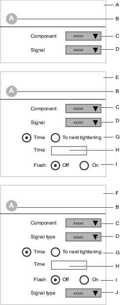
A | Component type (input) | B | Component identifier |
C | Component type selection | D | Signal selection from a drop-down list |
E | Component type (output) | F | Component type (input and output) |
G | Output signal duration selection | H | Output signal duration time |
I | Output signal flash selection On or Off switch | J | Input signal selection from a drop-down list |
The selection of signals in the drop-down menu depends on the selected component.
Output Signal Configuration
An Output Signal can be mapped to a lamp, a stacklight, a siren, a buzzer or a terminal connector. The signal is valid during a programmable duration, or until the next tightening starts.
All the different accessories show where and how an output signal can be mapped.
Mapping an output signal to a position:
Select a component or a position.
Select a Signal from the drop-down menu.
Set the Duration switch to Time or to Next tightening.
If Time is selected, a parameter entry box is displayed. Enter the duration of the output signal in seconds.
Set the Pulsating position switch to On for a flashing or intermittent signal, or to Off for a steady signal.
If the position is a stacklight, a Rotating option is also possible.
Input Signal Configuration
An input signal can be mapped to a button, switch or a terminal connector. The signals are continuously sampled by the controller.
Event input signals trigger the controller. One example is to press a push button and then release it.
State input signals are active as long as the signal is present. One example is a key switch. Another example is to press a push button and keep it pressed.
All the different accessories show where and how an input signal can be mapped.
Mapping an input signal to a position:
Select a component or a position.
Select a Signal from the drop-down menu.
Certain components, for example two-way switches, may be configured with two input signals.
Input and Output Combination
Certain components, like a push-button, may be mapped with both an Output Signal (lamp) and an Input Signal (button). The output signal is valid during a programmable duration or until the next tightening starts. The input signal is continuously sampled by the controller.
All the different accessories show where and how an output signal can be mapped.
Mapping an output signal to a position:
Select a component or a position.
Select a component type from the drop-down menu. The following selections and parameter entry boxes, depend on the selected component type.
Select an Output Signal from the drop-down menu.
Set the Duration switch to Time or to Next tightening.
If Time is selected, a parameter entry box appears. Enter the duration of the output signal in seconds.
Set the Pulsating position switch to On for a flashing or intermittent signal, or to Off for a steady signal.
Select an Input Signal from the drop-down menu.
Configuration Types
Internal I/O
The controller has two screw terminals located on the inside. They can be used to connect digital input and output signals.
All the digital input signals and the digital output signals that are listed in the Reference section can be routed to the internal I/O terminals.
For electrical specification and connections, see the controller documentation.
How to assign an accessory configuration to a Virtual Station is described in the Virtual Station  section.
I/O Expander
The I/O expander is connected to the I/O bus and provides an extension to connect digital input and output signals. Multiple expanders can be connected. Read the I/O expander documentation for address configuration and specifications of connections.
How to assign an accessory configuration to a Virtual Station is described in the Virtual Station section.
Operator Panel
The Operator Panel is connected to the I/O bus and provides a configurable digital communication link between an operator and the controller. Lamps, buttons, buzzers and switches are used in the communication. Read the operator panel documentation for address configuration and specifications of connections.
How to assign an accessory configuration to a Virtual Station is described in the Virtual Station section.
Socket Selector
Viewing/Editing or Creating a Socket Selector Configuration
The Socket Selector is connected to the I/O and assists the operator in selecting the correct socket for the tightening procedure.
Select a controller in the Plant Structure
. Go to Configurations
.The workspace area displays a list of created configurations for the selected controller.
Double-click on the name of the selected Socket Selector configuration in order to view or edit the configuration.
In Configurations
, selectAdd.The Create new configuration dialog window is displayed. Choose Socket Selector form the drop-down list, and then select Add.
In the Properties area of the menu, enter a configuration name and description.
In the Socket Selector Configuration, choose Control type Auto or External.
For each socket position that should be active, select the check box
 .
.For each socket position that should be inactive, clear the check box.
To add or remove a group of four sockets, select either Add or Remove.
Up to 32 socket selector positions can be used.
More information on how a configuration is addressed and assigned to a Virtual Station is given in the Virtual Station section .
Socket Selector Control Switch
The Control switch has two positions:
Position | Description |
|---|---|
Auto | The controller controls the LED lamps on the Socket Selector, which guide the operator to the correct socket selection. |
External | The controller has no control of the socket selector. All functionality of the LED lamps is controlled by an external control system through the Open Protocol communication or by the Fieldbus module. |
Stacklight
The Stacklight provides long distance visual communication from the controller to the operator. In addition to the lights, the accessory can be equipped with a button, key switch, buzzer and I/O connections.
The Stacklight is connected to the controller using the I/O bus. Multiple accessories can be connected on the I/O bus. Read the Stacklight documentation for address configuration and specifications of the connections.
How to assign an accessory configuration to a Virtual Station is described under the Virtual Station icon .
Scanner
The Scanner is an accessory, it is installed directly to the controller via a USB cable.
In the Scanner configuration it is possible to configure the Pass through as On or Off. As default the configuration is Off. When Pass through is activated (set to On), the scanned barcode information is sent to either SoftPLC, or Fieldbus for decoding.
In the Plant structure workspace
, select a controller.In the tab menu bar in the workspace area, select the Configurations icon
.The workspace area displays a list of configurations.
Double-click on a configuration row that has Scanner in the Type column.
Alternatively, select Add to create a new scanner configuration.
Parameter | Description |
|---|---|
Name | Optional name for the configuration |
Description | Optional configuration description |
Pass through = On | The scanned barcode is sent to either SoftPLC, or Fieldbus to be decoded |
Pass through = Off | The scanned barcode is decoded in the controller |
Indicatorbox
The Indicatorbox is a flexible display indicator used to display status signals from the controller. The display is equipped with 20 dual color LEDs, these are mounted in a square with five LEDs at each side.
Configuring the Indicatorbox
Select Indicatorbox in the Configurations
menu. To add an LED click on the Add button.
Select LED letter in the Position box according to the illustration.
Select signal for red and green LED.
To remove an LED, select the LED and click on the DELETE button.
Tool Configuration
Tool Configuration - Properties Menu
The Tool configuration should be given a unique name. An optional description field is also available.
The accessory configuration list displays all configurations in an alphabetical order
To view or edit a tool configuration menu:
Select a controller in the Plant structure workspace
.Select the Configurations icon
in the menu bar.The workspace area shows a list of all the current accessory configurations.
Double-click on the name of the selected Tool configuration.
The workspace area shows the details of the current configuration and is divided into different menus, one for each topic.
Enter a configuration name and a description in the Properties menu.
Select a tool type from the Filter by tool type drop-down menu.
As the number of tools grows, the number of menus grows as well. To increase the visual comfort in the workspace, it is possible to filter menus and only show what is relevant for one selected tool type. The filter is set in the Properties menu. If No tool is selected, all the possible tool configuration parameters are displayed.
Tool Configuration - General Configuration
Inactivity timeout | Description |
|---|---|
On | Only valid for battery tools. In order to save battery time there is an option to automatically turn off the tool after a certain time of inactivity. Enter a value between 1-1440 minutes. |
Off | The tool will not be turned off due to inactivity. |
Front LED | Description |
|---|---|
Front LED enabled | Wireless tools: Off - Tool Front LED will always be off. On - Front LED is lit when the tool trigger is pressed, plus time set in Front LED duration starting at trigger release. Cable tools: The front LED is lit for 10 seconds after the tool trigger has been pressed. |
Front LED duration | Wireless tools: Front LED duration in seconds, starting when the tool trigger is released. |
Use Start source to set how to start the tool.
Start source | Description |
|---|---|
Trigger only | Press the tool trigger to start the tightening. |
Trigger OR Push | Press the tool trigger or push the tool against the joint to start the tightening. |
Trigger AND Push | Press the tool trigger and push the tool against the joint to start the tightening. |
Push only | Push the tool against the joint to start the tightening. |
Digital input | Using an external digital input signal to trigger the start of the tightening. |
Safety trigger | Applicable only on tools that have two triggers. The two triggers must be pressed simultaneously to start a tightening or loosening. Both triggers must be released between consecutive tightenings. |
Use Trace start to set how to start the tightening trace.
Trace start | Description |
|---|---|
Off | No data tracing. |
Trigger pressed | Data tracing of the tightening process starts as soon as the trigger is pressed. |
Rundown complete | Data tracing of the tightening process starts when the Rundown complete is detected. |
The Start request switch defines the action when communication between tool and controller is lost.
Start request enables the requirement of having a connection between the tool and the controller, for all battery tools. This to make sure that the tool is always up to date with tightening program or batch settings, and with other settings on the controller, when performing tightenings.
When Start request is set to On, the tool becomes locked if the controller connection is lost. This means that if the tool loses connection in the middle of a tightening or a batch sequence, the tool will finish the ongoing tightening and then stop. The tool will be locked until the connection is re-established.
Start request | Description |
|---|---|
On | The current Tightening program is finished and subsequent tightenings are stopped when the connection is lost between the controller and the tool. |
Off | Current Tightening program or Batch can be finished even if the connection is lost between controller and tool. |
The TAG number is the RFID TAG which is used to identify the end-fitting tool in the STwrench. The following options are available:
TAG check | Description |
|---|---|
On | Check the TAG number of the End-fitting tool (socket). The TAG number must be identical to the number in the Tightening program configuration. |
Off | No TAG checking is done. |
TAG selection | Description |
|---|---|
On | Use the TAG number of the End-fitting tool (socket) to select a batch in a batch sequence. The TAG number must be written into the identifier number field in the Sequence configuration menu in the batch sequence section |
Off | The TAG value is not used to select a batch. |
 .
. Lock tool on memory full gives the tool the possibility to perform tightenings even when the tool memory is full. This means that the tightenings performed when the tool memory is full will never be reported to the controller.
Lock tool on memory full | Description |
|---|---|
On | The tool will be locked from further tightening operations when the tool memory is full. In order to resume tightening operations the tool has to reestablish connection to the controller and send the tightening results that have been stored in the tool memory. |
Off | The tool will continue to perform tightenings even when the tool memory is full. |
Tool Configuration - Direction Switch
The Direction Switch on the tool can be configured to trigger one input signal when quickly switched from clockwise (CW) to counter clockwise (CCW) and back, or vice versa.
Tool Configuration - Function Button
Use the tool's Function Button to control up to six of the available input signals. The buttons have three possible condition states that are combined with the two possible states of the direction switch.
Function button states | Direction switch states |
|---|---|
Pressed | CW |
Single push | CW |
Double push | CW |
Pressed | CCW |
Single push | CCW |
Double push | CCW |
Two configurable parameters controls the push time.
Parameter | Description | Default value |
|---|---|---|
Push detection interval (ms) | For single push: the maximum push time (in milliseconds) between the button being pressed and the button being released. | 300 ms |
Next push interval (ms) | For double push: the maximum time (in milliseconds) between the button being released after the first push, and the button being pressed again. | 300 ms |
Tool LEDs
The tool LED's can be used to signal different messages to the operator.
Select a controller in the Plant structure workspace
.Select the Configurations icon
in the top-side menu bar in the workspace area.The workspace area displays a list of configurations.
Double-click on a configuration row that has Tool configuration in the Type column.
Alternatively, select Add to create a new configuration.
The workspace shows all the tool configuration menus.
Perform the relevant configurations. The configurations are auto saved in ToolsTalk 2.
The tool LEDs have the following features
The blue LED is on top of the tool. An output signal can be connected to the LED and provides an output message to the operator.
The LED ring consists of a red, a yellow and a green ring. Output signals can be connected to the LEDs and provide output messages to the operator.
A result indicator uses the LED rings. Tightening result signals can be connected to the LEDs and provide output messages to the operator at the end of the tightening.
Blue LED
The blue LED is a single LED with a steady signal.
Select the signal that shall be connected to the blue LED from a shortcut menu.
For a signal of the type Event, select the duration of the signal.
LED Ring
The LED Ring consists of three circles of LED lamps. One circle of red LEDs, one circle of Yellow LEDs and one circle of Green LEDs. Each circle can have a steady signal or a flashing signal. This provides a total of six different signals that can be connected to the LED ring.
Select the signal that shall be connected to the LED color and type from a shortcut menu.
For a signal of the type Event, select the duration of the signal.
An LED is turned on only when no tightening is ongoing and when the controlling output signal is activated.
An LED is turned off when the maximum time is exceeded. Only applicable if the signal type is an Event.
An LED is turned off when the next tightening is started.
An LED is turned off when the controlling output signal is deactivated. Only applicable if the signal type is a State.
Result indicator
A pre-configured pattern can be selected from a shortcut menu. This pattern can be a combination of tightening results.
Select the signal message that shall be displayed from a shortcut menu.
Select the duration of the message.
Signal | Description |
|---|---|
Off | No LEDs are activated after the tightening, regardless of the result |
Green | If a result indicator is selected, a green light is the default signal if the tightening is terminated correctly (OK). |
Red:high:yellow:low | Either a red LED indicates the final value is too high, or a yellow LED indicates the value is too low, if the tightening is terminated incorrectly (NOK). |
Red:NOK:yellow:low | A red LED indicates that the tightening is terminated incorrectly (NOK). An additional yellow LED can indicate if the value is too low. |
Red:NOK | A red LED indicates that the tightening is terminated incorrectly (NOK). No additional LEDs are shown. |
An LED is turned on when a tightening is terminated and the LED is part of the result indicator configuration.
An LED is turned off when a tightening has been performed and the LED is not part of the result indicator configuration.
An LED is turned off when the maximum time is exceeded after a tightening has been performed.
An LED is turned off when the next tightening is started.
An LED is turned off and replaced by another LED signal pattern when an LED ring configuration is activated by an output signal.
An output signal can be of the type Event or of the type State.
A state signal is active as long as the state is active.
An event signal is active during a programmable time range.
Tool Configuration - Buzzer
The Buzzer can be configured to emit different sounds. Output signals can be mapped to each of the signals and provides an audio interface to the operator.
The Buzzer is located on the tool and is configured as a tool accessory.
Command | Description |
|---|---|
Add | Add a new sound configuration to the table. |
Delete | Remove one or more selected sound configurations. |
Up to 20 different signals can be mapped to a sound and each sound can have its own characteristic profile, with parameters described in the table below.
Parameter | Description |
|---|---|
Check box | Selects a row in the table. |
Signal | Select a signal that triggers the sound. |
Frequency | Exact frequency in Hz. |
Time on | Time (in ms) that the buzzer emits a sound. |
Time off | Time (in ms) that the buzzer is quiet. |
Repetition | Number of times the buzzer repeats the on/off sequence. |
Volume | The buzzer volume, in percentage of max volume. |
Priority | 10 different priority levels are available for the sounds where one (1) is the highest priority level. Default priority level is five. |
For two simultaneous signals, the signal with highest priority overrides the other signal.
A buzzer signal runs until termination and is not interrupted by a higher prioritized signal.
Configuring the Tool Accessory Bus
A StepSync controller does not support this accessory.
The optional tool accessories can be factory installed or be installed at a later stage. The accessories are connected to a Tool Accessory Bus. They have small displays as outputs, and buttons as inputs. The functionality is configured from the controller GUI, the web GUI or the ToolsTalk 2 GUI.
The hardware installation of a tool accessory is described in the accessory documentation and in the tool's specific documentation. The configuration parameters that can be accessed from ToolsTalk 2 are described in this documentation.
Select a controller in the Plant structure workspace
.Select the Configurations icon
in the top-side menu bar in the workspace area.The workspace area displays a list of configurations.
Double-click on a configuration row that has Tool configuration in the Type column.
Alternatively, select Add to create a new tool configuration.
Double-click on a configuration to open the selected configuration menu.
The Accessory bus menu shows the possible accessories that can be configured.
Double-click on the selected type to open a shortcut window for the configuration.
Type | Description |
|---|---|
ST selector | A small display and buttons; used to select tasks or programs according to the configuration. |
TLS tag | Tool Location System tag; used to provide output signaling to the operator. |
EHMI | A small display and buttons; used to select tasks or programs according to the configuration. |
Scanner | Installed on the tool and connected to the tool accessory bus. It has one function button that activates the Scanner. |
Configuring the Tool Location System Tag (TLS)
A StepSync controller does not support this accessory.
The Tool Location System (TLS) tag, is a tool accessory. The TLS tag is installed on the tool and connected to the tool accessory bus. The TLS tag is part of the Ubisense positioning system and is handled independently from the controller. In addition to the positioning, the TLS tag can be used to provide information to the operator. Selected output signals can generate different LED light combinations.
Select a controller in the Plant structure workspace
.Select the Configurations icon
in the top-side menu bar in the workspace area.The workspace area displays a list of configurations.
Double-click on a configuration row that has Tool configuration in the Type column.
Alternatively, click the Add command button to create a new Tool Configuration.
Double-click on the TLS Tag in the Accessory bus menu, to open a shortcut window for the configuration.
Make the selected configurations. The configurations are auto-saved in ToolsTalk 2.
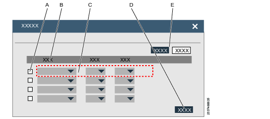
A | Check box | B | Table header row |
C | Table row, with shortcut menus | D | Command button |
E | Command button |
Command | Description |
|---|---|
Add | Add a new configuration to the table. |
Delete | Remove one or more selected configurations. |
Close | Close the shortcut menu. |
Up to 10 different output signals can be mapped to a light priority.
Parameter | Description |
|---|---|
Check box | Select a row in the table. |
Signal | Select a signal from a shortcut menu, that triggers the LED light. For a signal of the type Event, select the duration of the signal. |
Color | Select a color for the LED. |
Priority | 10 different priority levels are available for the sounds where one (1) is the highest priority level. Default priority level is five (5). |
If there are two simultaneous signals, the signal with the highest priority takes precedence. When two signals with the same priority trigger the LED, the first signal received takes precedence.
An output signal can be of type Event or of type State.
A state signal is active as long as the state is active.
An event signal is active during programmable time.
Configuring the Extended Human Machine Interface (EHMI)
The EHMI is a tool accessory. It is installed on the tool and connected to the tool accessory bus. It has a graphical display, three function buttons and an optional scanner. The display is a subset of the controller GUI with the possibility to select tightening programs, batch sequences etc. Through the function buttons, the operator can interact with the controller.
A StepSync controller does not support this accessory.
In the EHMI configuration, it is possible to configure whether the function buttons should be set to On or Off.
Select a controller in the Plant structure workspace
.Select the Configurations icon
in the top menu bar.The workspace area displays a list of configurations.
Double-click on a configuration row that has Tool configuration in the Type column.
Alternatively, select Add to create a new Tool configuration.
Double-click on the EHMI in the Accessory bus menu, to open a shortcut window for the configuration.
Make the selected configuration. The configurations are auto-saved in ToolsTalk 2.
Parameter | Description |
|---|---|
Function buttons = On | The buttons have full functionality to configure settings within the visible menus. |
Function buttons = Off | The function buttons can only be used to acknowledge a necessary dialog on the EHMI |
Configuring the ST Selector
The ST Selector is a tool accessory. It is installed on the tool and connected to the tool accessory bus. It has a small display, two input buttons and output LEDs.
A StepSync controller does not support this accessory.
Select a controller in the Plant structure workspace
.Select the Configurations icon
in the top-side menu bar in the workspace area.The workspace area displays a list of configurations.
Double-click on a configuration row that has Tool configuration in the Type column.
Alternatively, select the Add command button to create a new configuration.
The workspace shows all the tool configuration menus.
Double-click on the ST selector in the Accessory bus menu, to open a shortcut window for the configuration.
Make the selected configurations. The configurations are auto-saved in ToolsTalk 2.
Display
The display can show one piece of information at a time and has five different messages that roll in the display with a configurable display time.
Parameter | Description |
|---|---|
Switch time | Select the time to display one message before the next message is displayed. |
Page | For each page 1-4, select a message from the shortcut menu that is to appear in the display for the duration of the switch time. |
Buttons
The two buttons can be configured to act upon the displayed information and can be used to step through the listed items.
Parameter | Description |
|---|---|
Left button | Select one action from the shortcut menu. |
Right button | Select one action from the shortcut menu. |
Status LEDs
The status LEDs can be activated or deactivated.
Parameter | Description |
|---|---|
Enable result LEDs | Select the desired On or Off radio button. |
Enable extra LEDs | Select the desired On or Off radio button. |
The result LEDs which are red, green and yellow, show the same information as the main tools LEDs.
The two extra LEDs can show Batch OK and Batch sequence OK. Both these LEDs are automatically turned off at the next tightening.
General Virtual Station
In the Plant structure workspace
, select a controller.In the tab menu bar in the workspace area, select the Configurations icon
.The workspace area displays a list of configurations.
Double-click on a configuration row that has General Virtual Station in the Type column.
Alternatively, select Add to create a new General Virtual Station configuration .
Parameter | Description |
|---|---|
Name | Optional name for the configuration |
Description | Optional configuration description |
The non-tightening results can either be reported unfiltered (default), or configured to report a selection of the results. Up to 16 General Virtual Station configurations can be created.
Non-tightening results affected:
Loosening
Batch increment
Batch decrement
Reset batch
Bypass tightening program
Abort batch sequence
Reset batch sequence
When using a StepSync or a Flex controller the following parameter is also visible in the General Virtual Station configuration.
Fixtured Stations
Auto Enable can use one of the following settings, the default setting is Never.
Setting | Description |
|---|---|
Never | Input Enable Operation must be set high to be able to run a tightening. |
Always | It is always possible to run tightenings regardless of the status of input Enable Operation. |
Creating a Non-tightening result filter
Default is set to "On" - all results will be reported. Switch to "Off" to filter the results, only filters set to "On" are reported.
The non-tightening results will always be displayed in the controller and web user interface, regardless of what is filtered to the report.
To apply the General Virtual Station configuration, assign it to a Virtual Station in the Virtual Station
section.
Only unassigned General Virtual Station configurations can be deleted.
Enabling and Disabling the Tightening Settings
The General Virtual Station configuration contains a tightening section, which is used to set parameters for Disable tightening and Disable loosening.
Select a controller in the Plant structure
. Go to theConfigurations tab
in the menu bar.The workspace area displays the available Configurations.
Double-click on an existing General Virtual Station to configure, or select Add to create a new one to configure.
Make the relevant selections in the Tightening Settings parameters, according to the information in the tables below.
Parameter Value | Description |
|---|---|
Off | A disabled tool will remain disabled regardless of the loosening status. |
On OK | A disabled tool will be unlocked after an OK loosening has been performed. |
Always | A disabled tool will be unlocked as soon as a loosening has been performed, regardless of the loosening status. |
Disable loosening | Description |
|---|---|
Off | Disable loosening is Off. An operator can always loosen a screw. |
On OK tightening | Disable loosening for an OK tightening. An operator cannot loosen a screw that was terminated with tightening OK. |
On NOK tightening | Disable loosening for an NOK tightening. An operator cannot loosen a screw that was terminated with tightening NOK. |
Always | Disable loosening is always ON. An operator can never loosen a screw. |
Disable tightening | Description |
|---|---|
Off | Disable tightening is Off. An operator can always tighten a screw. |
On OK tightening | Disable tightening after an OK tightening. An operator cannot tighten another screw if the current tightening terminated with OK. |
On NOK tightening | Disable tightening after a NOK tightening. An operator cannot tighten another screw if the current tightening terminated with NOK. |
After every tightening | Disable tightening is activated after every tightening. An operator cannot tighten another screw until the current tightening is terminated. |
Tool lock behavior
Tool lock behavior is set to Off by default. This behavior can be overridden to allow the tool to be unlocked by the operator by performing a loosening.
Allowing a disabled tool to unlock after loosening
In the configuration used by the tool (set in the Virtual Station the tool is connected to), set the Unlock tool on loosening to On OK or Always.
In order to enable the setting above, three conditions need to be met:
1. The Disable loosening parameter cannot be set to Off or Always.
2. The Disable loosening value cannot be set to the same value as the Disable tightening.
3. The tightening program used must have loosening enabled.
When the tool is locked for either tightening or loosening due to a disable state, it can be unlocked by any of the following input signals:
Master_Unlock
Unlock_Tool_On_Disable
This input signal can be sent to the controller either from an accessory, from a programable tool accessory, or from the Fieldbus unit.
Working with the Controller Information Tab
The menus in the Controller Information  tab provide information about a single selected controller.
Viewing the Controller Information menus:
Select a controller in the Plant structure workspace
.Go to theController
tab.The workspace area displays the Controller menus.
In the Controller workspace, the following menus are shown:
Menu | Functionality |
|---|---|
Controller information | Provides general information about the controller and the IAM module. |
Licenses | Provides information about the different license types which have been issued to the controller. |
Software | Provides information about the software configuration of the controller. |
Hardware | Provides information about the hardware configuration of the PF6 controller. |
Export / Import | Provides export of controller results and configurations, and import of controller configurations. A dialog box appears to for file location. |
Health | Monitors and records environmental parameters and system health parameters. |
The information displayed is for information only. No setting of parameters is possible in the menus.
Controller Information and IAM Menu
The Intelligent Application Module (IAM) is located on the inside of the controller door. It contains the controller program, configuration parameters and stored results.
The IAM module can easily be removed and moved into another controller, which then will behave exactly as the previous controller.
Viewing the Controller information Menus and Current Configurations
Select a controller in the Plant structure
.Go to Controller
.The workspace area displays the Controller menus.
Menu | Functionality |
|---|---|
Model | Provides general information about the type of controller. |
Serial number | Provides information about the serial number of the controller. |
Service Ethernet port | Provides information about the IP address of the service port. Through this port a service engineer can access the controller without being connected to the factory network. |
Menu | Functionality |
|---|---|
Type | Atlas Copco provides different IAM types with different functionality. |
Customer key | Is an identifier for application-specific or customer-specific configurations. |
Serial number | Provides information about the serial number of the IAM module. |
Software Menu
Select a controller in the Plant structure workspace
.Go to Controller
.The workspace area displays the Controller menus.
Menu | Functionality |
|---|---|
Current version | The main active working software. |
Stored version | A stored inactive software. |
It is possible to switch between installed software versions and this has two advantages:
Controller software can be loaded to controllers in parallel to normal operation. If several controllers are to be updated, a switch can then be made very quickly on all controllers at the same time.
If a software upgrade results in unexpected results, a switch to the previous version is a quick back-up fix.
Licenses
This field displays the available license types and features that have been issued to the controller.
Hardware Configuration
This menu provides information about the system hardware configuration.
Select a controller in the Plant structure workspace
.Go to Controller
.The workspace area displays the Controller menus.
For a Power Focus 6000 controller the menu is named Hardware. The information lists the different hardware modules that make up the controller.
For each module, the following data is provided:
Serial number
Article number
Hardware revision number
For more controller hardware descriptions, please look into the Power Focus 6000 controller documentation.
For a FlexController the menu is named Channels. The information lists the different hardware drives and tools that make up the controller.
Export and Import
The export and import function is used to export the events and tightening results accessible in the Results menu for analysis in external programs, as well as allowing transfer of tightening program, batch, and controller configurations between controllers.
The command Export can be used for the following reasons:
Exporting tightening results and events for further processing.
Exporting log files for debug assistance from an Atlas Copco service engineer.
Exporting the entire controller configuration that can be used to copy the configuration to another controller.
Comparing two exported configurations to see differences.
Select a controller in the Plant structure
.Go to Controller
.The workspace area displays the Controller menu.
Click the Export button to export one of the following:
Parameter
Description
Export
Exports all controller information.
Export Configuration
Exports settings and configurations.
Export Tool Log
Exports logs (tightenings and hardware information) from connected tools. Available for SRB, TBP and STB.
The export consists of atlas_tool_i.zip and ExportInfo.txt
Select the location for saving the export file, click OK.
Select a controller in the Plant structure
.Go to Controller
.The workspace area displays the Controller menu.
To import controller configurations, click the Import command button.
Click Open file. Select the file to import.
The import file must be a previously exported file.
When using the import function, all settings for tightening program, batch, accessories, and controller are replaced by the settings from the import file. However, settings for network, PIN, and results and events are not imported.
System Health Monitor
The equipment health monitor regularly measures parameters and stores them.
Select a controller in the Plant structure workspace
.Go to Controller
.The workspace area displays the Controller menus.
The Health menu displays environmental data and system health information.
Information | Value | Description |
|---|---|---|
Refresh command button | Degree C or F | Reads information from the controller and displays the latest result. |
Controller temperature | Degree C or F | Latest temperature recording expressed in month/day/year hour:minute:second. |
Battery status | OK/NOK | Monitors the memory and real time clock battery in the controller computer board. Status message NOK, means the battery needs to be changed as soon as possible to avoid loss of data or wrong results. Latest recording expressed in month/day/year hour:minute:second. |
History command button | Provides a list of monitor readings. |
Working with the Fieldbus and SoftPLC Tab
The Fieldbus and SoftPLC are located in the Fieldbus and SoftPLC
tab, when a single controller has been selected in the Plant structure
.
A fieldbus is a communication link between a factory management system (fieldbus master) and a remote node (fieldbus subordinate). A node can be complex, like a controller, but may also be a simple unit, like a sensor or a valve.
The Fieldbus and SoftPLC tab is divided into four sections:
Overview configuration
Fieldbus configuration
Acyclic Data configuration - Only available for StepSync.
SoftPLC configuration
Overview Configuration Tab
Fieldbus settings
The Connection status can show the following status messages:
Status | Description |
|---|---|
Fieldbus_Online | The fieldbus module is online. The communication between the controller and the fieldbus master is active. |
Fieldbus_Offline | The fieldbus module is offline. The communication between the controller and the fieldbus master is not active. |
Fieldbus_NoModuleInstalled | No fieldbus module is detected in the controller. |
Fieldbus_NotConfigured | A fieldbus module is detected in the controller but the module is not configured. |
Fieldbus_Initializing | A fieldbus status during reset or as a result when global parameters have been changed. This is a temporary status until a steady status is displayed. |
The fieldbus status can also show errors:
Error Code | Description | Action |
|---|---|---|
Fieldbus_ModuleMismatch | Supported module. Parameter mismatch detected. | Contact Atlas Copco to read error log. |
Fieldbus_UnsupportedModuleInstalled | Unsupported fieldbus module. | Contact Atlas Copco to read error log. |
Fieldbus_ConfiguredModuleNot Installed | Configuration data created. No module detected. | Contact Atlas Copco to read error log. |
Fieldbus_Unexpectedconfigurationerror | Mismatch between controller and ToolsTalk 2. | Contact Atlas Copco to read error log. |
Changing some global parameters like frame size, fieldbus module address, will cause the fieldbus module to reset.
Select a controller in the Plant structure workspace
.Select Fieldbus and SoftPLC
in the Menu bar then select the Overview sub-tab.In Fieldbus settings select Fieldbus type from the drop-down menu.
Enter the size in bytes of the entire Frame size for both the receive and transmit direction. The value must be an even integer number.
Enter the fieldbus type specific parameters.
Fieldbus Parameters General
Field | Description | Default value |
|---|---|---|
Fieldbus type | Select the fieldbus type from drop-down menu:
| Undefined |
Update interval | Set how often a Process Data Frame should be sent. The value is expressed in milliseconds. Minimum value is 100 ms. |
|
Lock tool when fieldbus offline | Selection switch On-Off. Determines the action taken by the controller if the fieldbus module loses communication with the fieldbus master (PLC). | Off |
Read result handshake | Selection switch On-Off. When turned On, the setting will affect all virtual stations. The signal Read Result Handshake has to be mapped in the fieldbus configuration. Any results produced when there are no results to acknowledge will immediately be sent to the PLC. Results to acknowledge will be put in a queue and when acknowledged it will be cleared and the next result in the queue is sent. The time between the cleared result and the next result in the queue is dependent on the cycle time for the fieldbus set in the general fieldbus settings. If the setting is changed, or if the fieldbus mapping for the virtual station is changed, the results still in the queue will be flushed and not sent to the PLC. | Off |
Set by network | Selection switch On-Off. Determines how the fieldbus module communication is configured.
| Off |
Sync on task selected | Off | |
Byte order Cyclic Data | Select which order of bytes is used for the cyclic data:
| Set by network |
Fieldbus parameters for ProfinetIO
The table below only lists specific parameters for ProfinetIO. For the general parameters, see Fieldbus Parameters General.
Field | Description | Default value |
|---|---|---|
Device name | Name of the device | |
Fieldbus node IP address | Format is 0.0.0.0 |
|
Subnet mask | Format is 0.0.0.0 |
|
Gateway | Format is 0.0.0.0 |
|
To controller | Total receive Process Data Frame. The frame size is a combination of all the virtual station receive frames. The size is expressed in number of Bytes. | |
From controller | Total transmit Process Data Frame. The frame size is a combination of all the virtual station transmit frames. The size is expressed in number of Bytes. |
The parameter Device name identifies the fieldbus module on the PROFINET and uses the syntax described in RFC 5890.
Fieldbus parameters for EtherNet/IP
The table below only lists specific parameters for EtherNet/IP. For the general parameters, see Fieldbus Parameters General.
Field | Description | Default value |
|---|---|---|
Fieldbus node IP address | Format is 0.0.0.0 |
|
Subnet mask | Format is 0.0.0.0 |
|
Gateway | Format is 0.0.0.0 |
|
To controller | Total receive Process Data Frame. The frame size is a combination of all the virtual station receive frames. The size is expressed in number of bytes. | |
From controller | Total transmit Process Data Frame. The frame size is a combination of all the virtual station transmit frames. The size is expressed in number of bytes. |
Fieldbus parameters for DeviceNet
The table below only lists specific parameters for DeviceNet. For the general parameters, see Fieldbus Parameters General.
Field | Description | Default value |
|---|---|---|
Fieldbus node address |
|
|
Baud rate | Speed of the communication link. Select speed from the drop-down menu. 125 kbps; 250 kbps; 500 kbps, Automatic. | Automatic |
Connection mode | Select the type of communication between the fieldbus master (PLC) and the subordinate controller. Select from a drop-down menu:
|
|
To controller | Total receive Process Data Frame. The frame size is a combination of all the virtual station receive frames. The size is expressed in number of bytes. | |
From controller | Total transmit Process Data Frame. The frame size is a combination of all the virtual station transmit frames. The size is expressed in number of bytes. |
Fieldbus parameters for Profibus
The table below only lists specific parameters for Profibus. For the general parameters, see Fieldbus Parameters General.
Field | Description | Default value |
|---|---|---|
Sync on task selected | If enabled the fieldbus frame shall be Re-synced at task changes | |
Extended mode | Chooses between the backward compatible152 bytes data mode and the 368 bytes data mode:
| |
Fieldbus node address |
|
|
Max ADI size | Choose between the different application data instance sizes to be set as a maximum. Data consistency is only guaranteed for data mapped over one single ADI, that is, if the data to be sent is larger, or broken over two ADIs, data consistency cannot be guaranteed. Setting a maximum ADI size, which is equal to the sent data type size and mapped correctly to the total frame size will guarantee data consistency. The maximum data size to use for sending cyclic data, which must match the data size used in the Fieldbus master. Max size ADIs will be used until less than that size remains to map. For example, If Max ADI size is set as 8 bytes, then that will be used for mapping until less than 8 bytes remain, then 4, 2, 1 bytes will be used to transfer the rest of the data. | |
To controller | Total receive Process Data Frame. The frame size is a combination of all the virtual station receive frames. The size is expressed in number of bytes. | |
From controller | Total transmit Process Data Frame. The frame size is a combination of all the virtual station transmit frames. The size is expressed in number of bytes. |
Fieldbus parameters for CC Link
The table below only lists specific parameters for CC Link. For the general parameters, see Fieldbus Parameters General.
Field | Description | Default value |
|---|---|---|
Baud rate | Speed of the communication link. Select speed from the drop-down menu. 156 kbps; 625 kbps; 2500 kbps; 5 Mbps; 10 Mbps. | 156 kbps |
Fieldbus node address | A unique address for each separate unit within the network | |
Version | Version 1: By default, the module automatically calculates the required number of Occupied Stations based on the mapped Process Data. Version 2: By implementing the Network Settings in the CC-Link, it is possible to customize the implementation for CC-Link Version 2 and use larger data sizes through Extension Cycles. | |
Occupied stations | A parameter setting which is dependent on which Version has been chosen. This is used in combination with the Extension Cycles parameter. | |
Extension cycles | Parameter setting used for sending larger data sizes, used in combination with the Version and Occupied Station parameters. | |
To controller | Total receive Process Data Frame. The frame size is a combination of all the virtual station receive frames. The size is expressed in number of bytes. | |
From controller | Total transmit Process Data Frame. The frame size is a combination of all the virtual station transmit frames. The size is expressed in number of bytes. |
Fieldbus parameters for CC Link IE
The table below only lists specific parameters for CC Link IE. For the general parameters, see Fieldbus Parameters General.
Field | Description | Default value |
|---|---|---|
Station number | Each device on the network must be assigned a unique Station Number. | |
Network number | The network can be segmented into several parts, each with a unique network number that is used for addressing. | |
To controller | Total receive Process Data Frame. The frame size is a combination of all the virtual station receive frames. The size is expressed in number of bytes. | |
From controller | Total transmit Process Data Frame. The frame size is a combination of all the virtual station transmit frames. The size is expressed in number of bytes. |
SoftPLC settings
Size
The inbound and outbound size allotted in the fieldbus for the PLC can be set in the To controller and From controller fields.
If the fieldbus for the PLC is not configured, the framesize will display 0 for both inbound and outbound size.
Offset
The order between fieldbus maps can be changed manually and the spacing between fieldbus maps can be controlled. Both of these two functions are controlled by the Offset parameter. This value defines the starting position of a fieldbus map in the Process Data Frame array.
Changing the Offset
In the To Controller section, type the offset of the fieldbus map within the Process Data Frame.
In the From Controller section, type the offset of the fieldbus map within the Process Data Frame.
Validation is done automatically. If the new offset value is accepted, it is shown in black text. If the value is not accepted an error message is shown in red text which provides information about which offset rule that is violated.
The start address must be an even number.
Fieldbus Virtual Station Mapping Configuration
A virtual station in a controller and the fieldbus master communicate by exchanging a fieldbus map between each other.
One or more fieldbus maps are combined into a Process Data Frame, which is sent on the physical communication link between the controller and the fieldbus master.
Column | Function |
|---|---|
Check box | Select or deselect a mapping. |
Virtual station | Name of virtual station. |
Fieldbus configuration | The fieldbus map. |
To/From controller offset | Starting point of the fieldbus map within the Process Data Frame. |
Viewing a Fieldbus Map assigned to a Virtual Station
To view how a fieldbus map is assigned to a virtual station:
Select a controller in the Plant structure workspace
. Select the Fieldbus and SoftPLC
tab then select the Overview sub-tab.
The Fieldbus Virtual Station Mapping Configuration menu displays a list of fieldbus maps, and to which virtual station they are assigned. The To Controller Offset column points to the address in the Process Data Frame where the fieldbus map starts.
Assigning a Fieldbus Map to a Virtual Station
Assigning a fieldbus map to a virtual station and placing it into the Process Data Frame:
Select a controller in the Plant structure workspace
. Select the Fieldbus and SoftPLC
tab then select theOverview sub-tab.Select Add in the Fieldbus Virtual Station Mapping Configuration menu.
The Add fieldbus mapping dialog window opens.
Select a Virtual station.
Select a Fieldbus configuration.
Select Add, the dialog window closes and the configuration is added.
Repeat steps 3-6 as many times as needed.
Fieldbus maps are placed into the Process Data Frame in the order that they are assigned to a virtual station, or at the lowest possible entry point where the Fieldbus map can fit.
Automatic Placement of Items in the Fieldbus Map
Items are placed automatically in the Fieldbus map. It is possible to change the order later by editing the Fieldbus window.
The following methods are used:
Items are placed in the order in which they are added to in the Fieldbus map, within the Fieldbus virtual station mapping configuration menu in Fieldbus and SoftPLC
.An item is placed at the lowest possible location with regards to byte, bit and length position.
If the item cannot fit in between existing items, the next free position in the array is tried.
If an item is deleted from the Fieldbus map, a gap will be created. When a new item is added, the placement algorithm will try to fill the gap.
If ToolsTalk 2 detects any violation of the placement rules. An error indicator
 will appear and indicate the error location. By placing the mouse cursor over the error indicator, more information about the rule violation is displayed.
Automatic Placement of Fieldbus Maps in the Process Data Frame
A Fieldbus map is placed automatically in the Process Data Frame when it is assigned to a virtual station. It is possible to change the order later by editing the Offset position in the Fieldbus virtual station mapping configuraiton menu in the Fieldbus and SoftPLC
tab.
The following methods are used:
A Fieldbus map is placed in the order in which they are assigned to in the Process Data Frame.
Each map starts with an Offset value from the beginning of the frame.
A map is placed at the lowest possible location, just above the previous map or with offset zero for the first map.
If a map is deleted from the Process Data Frame, a gap will be created. When a new map is assigned to a virtual station, the placement rule will try to fill the gap.
If the map cannot fit in between existing maps, then the next free position in the array is tried.
The offset value may be changed manually in the Settings window. Care must be taken that Fieldbus maps do not overlap.
If ToolsTalk 2 detects any violation to the placement rules, an error indicator  will appear beside the offset parameter. This indicates that maps overlap or that the map is outside the boundary. This may be corrected by changing the offset value.
A | Starting position of first Fieldbus map in the Process Data Frame; Offset = zero |
B | Starting position of a Fieldbus map in the Process Data Frame; Expressed as an offset from the beginning of the PDF |
C | Size of a Fieldbus map |
D | Fieldbus map |
E | Size of the Process Data Frame |
F | Error example; Blue map overlaps starting position of “green” map |
G | Map size |
H | Starting position of “blue” map |
J | Process Data Frame |
K | First map in the Process Data Frame; Offset address is zero |
Fieldbus Overview
A typical factory management control system that uses fieldbus communication can look like the figure below when it communicates with a controller.
A | Fieldbus master (PLC) | B | Frame header |
C | User data to and from several virtual stations inside the Process Data Frame | D | Virtual station |
E | Controller vith multiple virtual stations |
A fieldbus master, normally a PLC, exchanges information with a number of remote nodes which are called fieldbus subordinates. The master communicates with one subordinate at a time. The master transmits a frame to the subordinate and receives another frame in response.
The PLC transmits data to a anybus module which then communicates to the controller that may contain identification data, task selection information and other signals.
A controller sends responses to the PLC through the anybus module that may contain event signals, status signals, tightening results and other signals.
The update frequencies of the process data may differ. The update frequency between the controller and the anybus module is around 100Hz and the update frequency between the anybus module and the PLC is around 500Hz.
The physical transmission link depends on the selected fieldbus type. A transmission consists of a Frame Header, containing address information, and a Process Data Frame, which contains all the data.
If the controller supports virtual stations, it is important to direct the correct information to each virtual station. The Process Data Frame may contain one or more Fieldbus maps, one for each virtual station.
Fieldbus Configuration Parameters
An item is placed into the Fieldbus Map by defining the position of the least significant bit. This position is identified by a byte number and a bit number.
Information | Description |
|---|---|
Starting byte | The byte number in which the least significant byte of the item is located. A numeric number in the range from zero to size minus one. The numbering starts from zero (0). The least significant byte or bit is number 0. |
Starting bit | The bit number in which the least significant bit of the item is located. Starting from the previous selected starting byte. A numeric number in the range from zero to seven. The numbering starts from zero (0). The least significant byte or bit is number 0. |
Length | A numeric value representing the number of bits in the item. |
Range | Information only. Provides information of minimum length, the maximum length and the default length of the selected item. |
Converter | A drop-down list of available signal converters. This is used if the SoftPLC has any requirements on how items are represented in a digital format. |
The item converters are used to convert items between different data types.
Information | Description |
|---|---|
Boolean inversion | Inverts the digital signal from active high (1) to active low (0). |
Fixed-point |
|
Fieldbus Definitions
An Item is a digital signal. It can for example be signals, as they are described in the controller reference section:
A single bit of information, like Tightening OK.
Several bits of information, like an Event code.
An Item can be several bits of information representing a counter value, an identification number or a tightening result.
An Item can be a string of characters.
Information | Description |
|---|---|
Fieldbus Item | Boolean: The signal can be a simple boolean expression, occupying one single bit position. Examples are digital IO signals. |
Integer: The data occupies one or more bits of data in the array. | |
Character or string: The signal can be a alphanumeric character string, occupying one or several byte positions. |
Information | Description |
|---|---|
Fieldbus Map | An array of data. The Size must be an even number of bytes. The fieldbus map is created in the Fieldbus window in the Fieldbus menu. Fieldbus items are placed in the fieldbus map to create a unique array for the master-subordinate communication. Items are placed into the array by defining the starting position and the length, expressed in number of bits. |
Process Data Frame | An array of data. The size must be an even number of bytes. The Process Data Frame is created in the Fieldbus window in the Fieldbus menu. Fieldbus maps are placed into the Process Data Frame when they are assigned to a Virtual Station. The position of the map within the frame is defined by the Offset, which is calculated from the beginning of the frame. |
Fieldbus Configuration | Fieldbus mapping configurations are done in the Fieldbus window in the Fieldbus menu. Configuration parameters consist of both common parameters and type specific parameters. A list of parameter entry boxes are displayed after the fieldbus type has been selected. |
Information | Description |
|---|---|
Offset | A pointer variable. The signal can be a simple boolean expression, occupying one single bit position. Examples are digital IO signals. |
Starting Byte | A pointer variable. Points to a byte within the fieldbus map that contains the LSB of an item. |
Starting Bit | A pointer variable. Points to a bit in the previously defined byte within the fieldbus map that contains the LSB of an item. |
Item Length | A size variable expressed in a number of bits. |
LSB | Least Significant Bit or Byte. |
Name | Description |
|---|---|
Fieldbus Transmission | A datagram sent over the network. The transmitting node combines a Frame Header, containing address information, with a Process Data Frame that is sent to the network. The receiving node detects its address in the Frame Header and retrieves the Process Data Frame. |
Frame Header | Network address information and other data to ensure an error free transmission over the network |
Fieldbus Master | Typically a PLC that initiates the communication to a fieldbus subordinate. The master transmits a data frame and receives another frame from the subordinate. |
Fieldbus Subordinate | A remote node responding to a transmission from a fieldbus master. When the subordinate detects a transmission, it receives a frame and responds by sending another frame in return to the sender. |
Fieldbus Requirements
For correct fieldbus communication, the following installations and configurations must be made. This is done in the Fieldbus and SoftPLC
tab.
A fieldbus module is installed on the controller.
Common fieldbus parameters set in the menus in the Overview sub - tab.
Signal configurations are created in the Fieldbus sub-tab, which are then mapped in the Fieldbus Virtual Station Mapping Configuration menu in the Overview sub - tab.
Items mapped into fieldbus maps in the Signal Configuration menu, located in the Fieldbus sub - tab.
Fieldbus maps assigned to virtual stations and placed into the Process Data Frame in the menus in the Fieldbus and SoftPLC
tab.
SoftPLC Overview
The SoftPLC is used to customize the behavior of PF6/PFFlex, sending and receiving fieldbus data, or exchanging I/O signals to and from the external SoftPLC. The external SoftPLC is used for control of machinery on assembly lines. Configuration and programming is done through a third party software called MultiProg, integrated with ToolsTalk 2, though running in a process of its own. The SoftPLC is found in the Fieldbus and SoftPLC tab and is visible for controllers supporting this function either by license and/or capability.
Controller features, such as the Low Reaction Tightening Strategies and controller-wide functions among others, require licenses distributed through the Functionality Management System (FMS). Whereas configuration of features is possible without specific licenses, the assignment and use of those features will require the correct license to be installed on the controller. Please refer to Licenses (FMS) for more detailed information on licenses.
SoftPLC Requirements
The external SoftPLC configuration program, MULTIPROG 5.51 must be installed on the same computer as the ToolsTalk 2 client.
The SoftPLC must be set to On in the General SoftPLC settings, in order to run SoftPLC programs. On is indicated with status Running or stopped in the SoftPLC Status column. When in running mode, the SoftPLC process is active and ready to start or stop a SoftPLC program from Multiprog. A running SoftPLC program updates its values every 100 ms.
If a fieldbus is be used via SoftPLC:
Byte allocation for inbound and outbound SoftPLC signals can be done in the SoftPLC Settings section. This is located in the Overview sub-tab in the Fieldbus and SoftPLC tab.
If there already is a SoftPLC project for the controller, select the Fieldbus and SoftPLC tab and then select the SoftPLC sub-tab. In the Project area, select Open to open the Multiprog. Update SoftPLC framesize in fieldbus by selecting the Update button. Do this to see the Fieldbus settings that are updated in Multiprog.
Multiprog
Multiprog is the application where the actual SotPLC program is created and edited. When creating an initial project for a controller, variables and function blocks are created depending on the current setup of the controller and its capabilities. The templates will serve as a basic suggestion which can be further adjusted.
Fieldbus Configuration Tab
Select a controller in the Plant structure window
.Select the Fieldbus and SoftPLC
tab in the menu bar.Select the Fieldbus sub-tab to show the list of maps or to create a new fieldbus map.
Column | Description |
|---|---|
| Check box. |
Name | Name: Shows the name of the map. The name is identical for both the receive map and the transmit map. |
Size to | The size of the receive map to a virtual station. The value must be an even number of bytes. |
Size from | The size of the transmit map from a virtual station. The value must be an even number of bytes. |
Library link | Linked to global library Yes/No. |
Last changed | When were the last changes made, expressed in ToolsTalk 2 time. |
Changed by | Who made the last changes. |
Controller updated | Controller updated, expressed in controller time. |
Controller updated by | Who updated the controller. |
Creating a New Fieldbus Map
Select a controller in the Plant structure window
.Select the Fieldbus and SoftPLC
tab in the menu bar.Select the Fieldbus sub-tab to show the list of maps.
Select Add to create a new fieldbus configuration or double-click to edit an existing one.
The Create new fieldbus configuration dialog window opens.
Select the New tab.
Issue the configuration with a name.
Enter the Size to controller parameter. This is the receive size of the data frame to a virtual station, expressed in number of bytes. This value must be an even number.
Enter the Size from controller parameter. This is the transmit size of the data frame from a virtual station, expressed in number of bytes. This value must be an even number.
The transmit frame and the receive frame may have different size.
Select Add to continue with the configuration by adding items to the setup.
The map size entered can not be larger than the Process Data Frame.
Importing a Fieldbus Map
A previously exported fieldbus map can be reused as a template and be imported to a controller.
Select a controller in the Plant structure window
.Select the Fieldbus and SoftPLC
tab in the menu bar.Select the Fieldbus sub-tab to show the list of maps.
Select Add.
The Create new fieldbus configuration dialog window opens.
Select the Import tab to reuse a existing map.
Select the Open file command button to open a browser window.
Select a file. The file type must be a JSON file. (*.json).
Select Open. The browser window closes.
Select Add to import the file. This action will also close the pop-up window and the list of maps is updated.
Deleting a Fieldbus Map
Select a controller in the Plant structure window
.Select the Fieldbus and SoftPLC
tab in the menu bar.Select the Fieldbus sub-tab to show the list of maps.
For each fieldbus map to be deleted, select the check box
in the leftmost column in the fieldbus workspace. Select Manage, then Delete from the drop-down list.
The list of maps is updated.
Creating a Fieldbus Signal Configuration
In this area, you can create a new fieldbus signal configuration from the controller or to the controller.
Select a controller in the Plant structure window
.Select the Fieldbus and SoftPLC
tab in the menu bar.Select the Fieldbus sub-tab to show a list of maps.
Double-click on the name of a map to view it or select Add to create a new one.
The workspace shows the configuration menus.
Select the To Controller tab or the From Controller tab in Fieldbus configuration menu.
Select Add.
The Create signal configuration dialog window opens.
Select the item name in the list to select the item.
Set the item starting position by typing the BYTE number in which the least significant BIT is located.
Set the item starting position by typing the BIT in which the least significant BIT is located.
Set the Length of the item, expressed in number of bits.
Select an optional Converter value from the drop-down menu.
Select Add.
Repeat step 6-11 for every item to be added.
Select Close to terminate the adding operation and to close the dialog window.
If the item is not placed manually into the map, ToolsTalk 2 will try to place the item at the lowest possible position. It is possible to later move the item within the map.
Editing or Viewing an Item in the Fieldbus Map
Select a controller in the Plant structure window
.Select the Fieldbus and SoftPLC
tab in the menu bar.Select the Fieldbus sub-tab to show a list of maps.
Double-click on the name of the selected map.
The workspace shows the configuration menus.
Select either the To Controller tab, or the From Controller tab in Fieldbus configuration menu.
Double-click the item name in the map table in the Fieldbus configuration menu.
The Edit item dialog window opens.
Edit the item starting position by typing the BYTE number in which the least significant BIT is located.
Edit the item starting position by typing the BIT in which the least significant BIT is located.
Edit the Length of the item, expressed in number of bits.
Edit an optional Converter value from the drop-down menu.
Select OK to confirm any changes and to close the dialog window.
The Fieldbus configuration menu is updated in both the map and in the table.
Deleting Items From the Fieldbus Map
Select a controller in the Plant structure window
.Select the Fieldbus and SoftPLC
tab in the menu bar.Select the Fieldbus sub-tab to show a list of maps.
Double-click on the name of the selected map.
The workspace shows the configuration menus.
Select the To Controller tab or the From Controller tab in Fieldbus configuration menu.
For each item to be deleted from the map, select the check box
in the leftmost position in the table of items in the Fieldbus configuration menu.Select Delete .
The Fieldbus configuration menu is updated in both the map and in the table.
Exporting a Fieldbus Map
The Fieldbus map defines how signal items are placed into the communication frame that is used between a virtual station and a remote location. This map can be exported as a template and be imported and reused by another controller.
Select a controller in the Plant structure window
.Select the Fieldbus and SoftPLC
tab in the menu bar.Select the Fieldbus sub-tab to show the workspace and a list of maps.
In the leftmost column in the fieldbus workspace, select the check box
for the fieldbus map to be exported, and then select Manage followed by Export from the drop-down list.Browse to the desired location and select Save.
The map will be saved as a JSON file (*.json). The exported file can be imported to a different controller.
SoftPLC Configuration Tab
Creating a New SoftPLC Project
Select Create New to create a new SoftPLC project. This project will use a basic template as a starting point. This template includes all functions available in Multiprog.
The created and edited project is continuously saved to the local disc when the project is built and stored in Documents > Mp Temp. At ToolsTalk 2 SoftPLC startup, when clicking OPEN, the stored data project is uploaded and used if the SoftPLC project has not been saved to the ToolsTalk 2 server. Then editing can continue.
Select Create New. The Multiprog opens automatically.
Edit the SoftPLC program in Multiprog and give the project a Name and Description in ToolsTalk 2.
Add virtual station mappings with I/O signal configurations by selecting Update project virtual stations.
Add Fieldbus data by selecting Update project fieldbus framesize.
The fieldbus frame size must be configured to contain a special SoftPLC input/output part to be able to send and receive fieldbus data directly to/from the SoftPLC.
Select SAVE to check in the edited project to the ToolsTalk 2 server.
Push the changes to the controller.
Importing a SoftPLC Project Template
New SoftPLC projects can be created from an existing project template. The templates will serve as a basic suggestion which can be further adjusted. The selected project template is then copied, as to not overwrite the original project.
Select Import Project and select an existing SoftPLC project.
Edit SoftPLC project in the Multiprog.
Add virtual station mappings with I/O signal configurations by selecting Update in Project Virtual stations.
Add Fieldbus data by selecting Update in SoftPLC framesize in fieldbus.
Select Save to check in the edited project to the ToolsTalk 2 server.
Push the changes to the controller.
Select Update in Project Virtual Stations and the SoftPLC virtual station mappings are added or updated to the SoftPLC project, if not already included in the project.
Creating SoftPLC User Data
The SoftPLC can interact with protocol adapters through a dedicated part of the shared memory.
Select Add in the GENERAL SOFTPLC SETTINGS field.
In the Create SoftPLC user data window, choose the relevant protocol from the drop-down.
Fill in the TO SOFTPLC and FROM SOFTPLC address fields.
Select Add.
Select SoftPLC ON or OFF.
On: If the SoftPLC process is lost the tool will be locked from performing any tightenings.
Off: If the SoftPLC process is lost the tool will still be able to perform tightenings.
Creating SoftPLC Signal Configurations
Interaction between accessories and the SoftPLC is done through exchanging I/O signals.
Select Add in the SoftPLC Signal Configurations field to see the list with all supported I/O signals connected to this controller.
Clear the irrelevant signals in order to exclude them from the SoftPLC signal configuration (all signals are selected by default).
Name the signal configuration list.
The created signal configuration is then available as an option to select from the drop-down list when mapping the signal configurations to the virtual station.
The signals that are not included in a signal configuration (not checked), will still be visible in the SoftPLC configurator Multiprog, but crossed out.
Working with the Libraries Tab
The Library tab is located in left side menu bar, it includes global functions and provides the following functionality:
Library | Function |
|---|---|
 | Tightening program library This library contains all global tightening programs available for the controllers to subscribe to. The global tightening programs may be copied from one controller or created in the library, modified and/or distributed to one or more controllers. |
 | Configuration library This library contains all global configurations available for the controllers to subscribe to. The configurations may be copied from one controller or created in the library, modified and/or distributed to one or more controllers. |
 | Fieldbus configuration library This library contains all global fieldbus configurations available for the controllers to subscribe to. The fieldbus configurations may be copied from one controller or created in the library, modified and/or distributed to one or more controllers. |
| Settings library A library for Event configurations that can be distributed to other controllers. The events can be created here or in the Events section within the Settings |
| Program templates library Create templates for Multistep tightening program. When creating a new multistep program, the template can be inserted (drag-and-drop) and act as a base to build the multistep program on. |
 | Controller configuration library The controller configuration library contains controller templates that can be used to create and modify controller configurations and distribute them to multiple controllers. The library is also very useful for copying and developing configurations in Station Setup mode without access to a ToolsTalk 2 server installation. |
Libraries - Distribution List
The distribution list works like a subscription list. Whenever a change is made to one of the global configurations, the change is propagated to all subscribers. The distribution list manages the subscriptions.
Select Library
in the left-side menu bar. Select one of the following to view the distribution:
Global Tightening Program
 .
.Global Configuration library
 .
.Global Fieldbus library
 .
.Global Settings library
 .
.
Select one or more check boxes in the chosen library section to view the content of the distribution list.
The distribution list shows all controllers that subscribe to the currently selected configuration.
Tightening Program Library
Tightening Program Library Introduction
The combination of a tightening strategy selection and parameter values forms the tightening program, this is named as a tightening program. The tightening program can be either Global or Local.
A Local tightening program is valid for a single controller and a Global tightening program may have several controllers subscribing to the same tightening program.
A controller can subscribe to Global tightening programs. Whenever a change is made to a program, the change propagates to all controllers in ToolsTalk 2 which subscribe to the program.
The Tightening program library manages the global tightening programs and the controllers that subscribe to specific Tightening programs.
Updates to subscribers are made within the ToolsTalk 2 application. All affected controllers will show the Push indicator in the Line structure workspace.
ToolsTalk 2 can distinguish between a local and a global tightening program, although the controller itself has no knowledge of this. Therefore it is important to specify the action in ToolsTalk 2 if a tightening program is changed via either the controller GUI or the web GUI.
Tightening Program Library Workspace
Select Library
in the left-side menu bar. Go to Tightening program library
.The workspace area shows a list of Global tightening programs.
Column | Description |
|---|---|
Check box | Select a configuration. |
Name | Shows the name of the configuration. A Push indicator |
Strategy | The tightening strategy selected for the configuration. |
Global | A Yes in the column indicates that this is a global tightening program. |
Target | The final target is either expressed in a torque value or in an angle value. |
Last changed | When the last changes were made, expressed in ToolsTalk 2 time. |
Changed by | Which user made the last changes. |
Version | Controller software version that can support the Global tightening program library. |
| Not an actual column. The list of configurations can be sorted in rising or falling alphabetical order, numerical order or time order. Click on the table header row to make an arrow visible and click on the arrow to change the current sorting direction. One arrow is shown at a time. |
Controller type | Shows which controller type the tightening program is intended for. |

Command | Description |
|---|---|
Add |
|
Manage |
|
Select one or more Global tightening programs check box to view the distribution list. The distribution list shows all controllers currently subscribing to the selected programs.
If no global tightening programs exist, the work space area is empty. Select Add to create a new tightening program or double-click on an existing program to view or edit parameters.
Tightening Program Library - Adding a Global Tightening Program
Select Library
in the left-side menu bar. Go to Tightening Program
.The workspace area shows a list of Global tightening programs.
Select Add. The Create new tightening program dialog window opens.
Enter the parameters described in the table below.
Select Add in the dialog window. The window closes and the workspace shows the tightening program menus.
Parameter | Description |
|---|---|
Controller type | Select a controller type from the shortcut menu. |
Controller software version | Select a controller software version from the shortcut menu. |
Name | Issue the global tightening program with a name in the parameter entry field. |
Strategy | Select a tightening strategy from the shortcut menu. |
Target | Select a target type from the shortcut menu. |
Target value | Enter the numeric target value for the final step in the parameter entry field or fields. |
Tightening Program Library - Deleting a Global Tightening Program
Select Library
in the left-side menu bar. Go to Tightening Program
.The workspace area shows a list of Global tightening programs.
For each tightening program to be deleted, select the check box
in the leftmost column.Select Manage and then select Delete.
The global tightening program is removed from library and the list is updated.
The controllers subscribing to the deleted program do not lose the program. A deleted tightening program is removed from the list in the Tightening program library workspace. The tightening program is still present in the list in the Tightening workspace of the controllers that have subscribed to the global tightening program. The visible change is that the tightening program is transformed from being a global tightening program to a local tightening program. (The entry in the column Library link is cleared).
Tightening Program Library - Distributing Global Tightening Programs
Tightening Program Library - Adding a Global Program to the Distribution List
Select Library
in the left-side menu bar. Go to Tightening Program
.The workspace area shows a list of Global tightening programs.
Use the check box
to select one or more programs to be added to the distribution list.Select Manage and then select Distribute.
The Distribute global configurations dialog window opens.
The left-side column shows the selected Global tightening programs.
The right side column show a list of controllers that are compatible with the selected programs and can be added to the distribution list.
It is only possible to distribute between controllers of the same type and same software versions.
Use the check box
to select one or more controllers in the right-side column.If a controller already subscribes to the selected Global tightening programs it will not show up in the right-side column.
Optional step: Select the down arrow
 to open additional configurations.
Optional step: Select the action to be taken by ToolsTalk 2 if a global tightening program is changed by the controller GUI or web GUI.
Select Add.
The dialog window is closed.
ToolsTalk 2 can distinguish between a local and a global tightening program, although the controller itself has no knowledge of this. Therefore it is important to specify the action in ToolsTalk 2 if a tightening program is changed via either the controller GUI, or the web GUI. This action is defined in the distribution of a global tightening program in the tightening program library.
Tightening Program Library - Removing a Global Program Subscription from the Distribution List
The global tightening program distribution list is like a subscription list. Whenever a change is made to a global tightening program, the change is propagated to all subscribers. The distribution list manages the subscription.
Select one Global tightening program check box to view the content of the distribution list. The distribution list shows all controllers subscribing to the selected program.
Select a controller in the Plant structure workspace
.Go to Tightening program
 .
.The Tightening program workspace shows a list of tightening programs.
The entry in the column Library link is marked with Yes for the selected tightening program.
Select the check box
for the selected tightening program.Select Unlink.
The entry in the column Library link is cleared for the selected tightening program.
Select Library
in the left-side menu bar. Go to Tightening program library
.Select the check box
of the removed tightening program.The distribution list is updated and the controller name is removed from the list.
Tightening Program Library - Updating a Global Tightening Program
Select Library
in the left-side menu bar. Go to Tightening Program
.The workspace area shows a list of Global tightening programs.
Double-click on the name field, the tightening menus are editable. The changes are auto saved to the tightening program.
A global tightening program can only be edited or updated if the tightening menus are opened via the library path.
Updates to subscribers are made within the ToolsTalk 2 application. All affected controllers will show the Push indicator in the Plant structure workspace.
Global Configurations Library
Global Configurations Workspace
Select Library
in the left-side menu bar. Go to Configurations library
.The workspace area shows a list of Global configuration.
Column | Description |
|---|---|
Check box | Select a configuration. |
Name | Shows the name of the configuration. A Push indicator |
Type | The configuration type |
Last changed | When the last changes were made, expressed in ToolsTalk 2 time. |
Changed by | Which user made the last changes. |
Version | Controller software version that can support the Global configuration. |
| Not an actual column. The list of configurations can be sorted in rising or falling alphabetical order, numerical order or time order. Click on the table header row to make an arrow visible and click on the arrow to change the current sorting direction. One arrow is shown at a time. |
Controller type | Shows which controller type the configuration is intended for. |
Command | Description |
|---|---|
Add |
|
Manage |
|
Select one or more Global configurations check box to view the distribution list. The distribution list shows all controllers currently subscribing to the selected configuration.
If no global configurations exist, the work space area is empty. Select Add to create a new configuration or double-click on an existing configuration to view or edit parameters.
Global Configurations Library - Creating or Importing a Global Configuration
Creating a Global Configuration:
Select Library
in the left-side menu bar. Go to the Configurations library
in the upper menu bar in the workspace window.The workspace shows a list of Global configurations.
Select Add.
The Create new configuration dialog window is shown.
Enter the following parameters:
Select Type of configuration to be added, Controller type and Controller software version for the configuration to apply to.
Select Add in the shortcut window.
The configuration window for selected type of configuration is shown.
The configuration is auto saved to the Configurations library.
Importing an Already Existing Global Configuration:
Select Library
in the left-side menu bar. Go to Configurations library
.The workspace shows a list of Configurations.
To add a new configuration to the list, select Add.
The Create new configuration dialog window is displayed.
Select the Import tab.
Select Open file.
A browser window opens for reading the import file.
Select the desired import file. The file must be in the format <configuration_name>.json. Select Open.
Select Add in the shortcut window.
The configuration window for the imported configuration is displayed.
The configuration is auto-saved to the configurations library.
Global Configurations Library - Deleting a Global Configuration
Select Library
in the left-side menu bar. Go to Configuration library
.The workspace shows a list of Global configurations.
For each configuration to be deleted, select the check box
in the leftmost column.Select Manage and then select Delete.
The global configuration is removed from the library and the list is updated.
The controllers subscribing to the deleted configuration do not lose the configuration. A deleted global configuration is removed from the list in the Configuration library workspace. The configuration is still present in the list in the Configurations workspace of the configurations that have subscribed to the global configuration. The visible change is that the configuration is transformed from being a global configuration to a local configuration. (The entry in the column Library link is cleared).
Global Configurations Library - Creating a Global Configuration From An Existing
Select a controller containing the desired configuration in the Plant structure
.In the menu bar, go to Configurations
.Select one or more configurations to add to the library and click Manage, then select Add to library.
The selected local configuration will become a global configuration, stored in the Global configurations library.
If local changes are made in the controller or web interface, there are two options:
Auto revert: Changes in the controller will not apply to the global configuration, the global configurations will still be applied.
Unlink: Changes in the controller will apply to the configuration in the controller, and the link to the global configuration will be cut. As a result, the global configuration is immediately removed from the distribution list to the controller.
Select Library
. In the upper menu bar, Select Global configurations
.The workspace shows a list of Global configurations and the newly added configuration is now visible in the list.
Global Configurations Library - Distributing a Global Configuration
Select Library
in the left-side menu bar. Go to Configuration library
.The workspace shows a list of Global configurations.
Select the configuration check box
. Select Manage and then select Distribute.It is only possible to distribute between controllers of the same type and same software versions.
Use the check box
to select each configuration which is to be included in the distribution.Select one or more controllers in the right-side of the dialog window. Select Add in the dialog window.
Any updates to the global configuration will update the distributed copies. Changes in the global configuration will apply to the selected controllers.
If local changes are made in the controller or web GUI, there are two options:
Auto revert: Changes in the controller will not apply to the configuration, the global configurations will still be valid.
Unlink: Changes in the controller will apply to the configuration and the link to the global configuration will be cut. As a result, the global configuration is immediately removed from the distribution list to the controller.
The changes are auto saved to the global configurations library.
All affected controllers will show the Push indicator in the Plant structure workspace.
Global Configurations Library - Removing a Global Configuration Subscription From the Distribution List
The global configuration distribution list is like a subscription list. Whenever a change is made to a global configuration, the change is propagated to all subscribers. The distribution list manages the subscription.
Select one Global configuration check box to view the content of the distribution list. The distribution list shows all controllers subscribing to the selected configuration.
To remove the subscription of a Global configuration from one controller:
Select a controller in the Plant structure workspace
.Go to Configurations
.The Configurations workspace shows a list of tightening programs.
The entry in the column Library link is marked with Yes for the distributed configuration.
Select the check box
for the selected tightening program.Select Manage then Unlink from the drop-down menu.
The entry in the column Library link is cleared for the selected configuration.
Select Library
in the left-side menu bar. Go to Configurations library
.Select the check box
of the removed configuration.The distribution list is updated and the controller name is removed from the list.
Global Configurations Library - Editing a Global Configuration
Select Library
in the left-side menu bar. Select Global library
.The workspace shows a list of Global configurations.
Double-click the configuration to be edited. The configuration window for the selected type of configuration is shown.
The changes are auto saved to the global configurations library.
All affected controllers will show the Push indicator in the Plant structure workspace.
FIeldbus Configuration Library
The fieldbus configuration can be either Global or Local.
A Local fieldbus configuration is valid for a single controller and a Global fieldbus configuration is valid for several selected controllers.
A controller can subscribe to Global fieldbus configurations. Whenever any changes are made to a configuration it propagates to all controllers in ToolsTalk 2 that subscribe to the configuration.
The Global fieldbus configurations library manages the global fieldbus configurations and the controllers that subscribe to the configurations.
Updates to subscribers are done within the ToolsTalk 2 application. All affected controllers will show the Push indicator in the Line structure workspace.
ToolsTalk 2 can distinguish between a local and global fieldbus configuration, although the controller itself has no knowledge of this. Therefore it is important to specify the action in ToolsTalk 2 if a fieldbus configuration is changed via either the controller GUI, or the web GUI.
- Fieldbus Configuration Workspace
- Fieldbus Configuration Library - Creating or Importing a Global Fieldbus Configuration
- Fieldbus Configuration Library - Deleting a Global Fieldbus Configuration
- Fieldbus Configuration Library - Creating a Global Fieldbus Configuration from an Existing Fieldbus Configuration
- Fieldbus Configuration Library - Distributing a Global Fieldbus Configuration
- Fieldbus Configuration Library - Removing a Fieldbus Configuration Subscription from the Distribution List
- Fieldbus Configuration Library - Editing a Global Fieldbus Configuration
- Fieldbus Configuration Library - Exporting a Global Fieldbus Configuration
Fieldbus Configuration Workspace
Select Library
in the left-side menu bar. Go to Fieldbus library
.The workspace area shows a list of Global Fieldbus configuration.
Column | Description |
|---|---|
Check box | Select a Fieldbus configuration. |
Name | Shows the name of the Fieldbus configuration. A Push indicator |
Size to controller | Displays the receive size of the data frame. |
Size from controller | Displays the transmit size of the data frame. |
Last changed | When the last changes were made, expressed in ToolsTalk 2 time. |
Changed by | Which user made the last changes. |
Version | Controller software version that can support the Global Fieldbus configuration. |
| Not an actual column. The list of configurations can be sorted in rising or falling alphabetical order, numerical order or time order. Click on the table header row to make an arrow visible and click on the arrow to change the current sorting direction. One arrow is shown at a time. |
Controller type | Shows which controller type the Fieldbus configuration is intended for. |
Command | Description |
|---|---|
Add |
|
Manage |
|
Select one or more Global Fieldbus configuration check box to view the distribution list. The distribution list shows all controllers currently subscribing to the selected Fieldbus configuration.
If no global Fieldbus configurations exist, the work space area is empty. Select Add to create a new Fieldbus configuration or double-click on an existing configuration to view or edit parameters.
Fieldbus Configuration Library - Creating or Importing a Global Fieldbus Configuration
Creating a Fieldbus Configuration:
Select Library
in the left-side menu bar. Go to Fieldbus library
.The workspace shows a list of Fieldbus configurations.
To add a new fieldbus configuration to the list, select Add.
The Create new fieldbus configuration dialog window is displayed.
Enter the following parameters to add a new fieldbus map:
Enter a Name
Enter Size to controller and Size from controller
Select Controller type and Controller software version for the device, from the shortcut menu.
Select Add in the shortcut window.
The configuration window for the added fieldbus configuration is displayed.
The fieldbus configuration is auto-saved to the fieldbus library.
Importing an Already Existing Fieldbus Configuration:
Select Library
in the left-side menu bar. Go to Fieldbus library
.The workspace shows a list of Fieldbus configurations.
To add a new configuration to the list, select Add.
The Create new fieldbus configuration dialog window is displayed.
Select the Import tab.
Select Open file.
A browser window opens for reading the import file.
Select the desired import file. The file must be in the format <fieldbus_configuration_name>.json. Select Open.
Select Add in the shortcut window.
The configuration window for the added fieldbus configuration is displayed.
The fieldbus configuration is auto-saved to the fieldbus library.
Fieldbus Configuration Library - Deleting a Global Fieldbus Configuration
Select Library
in the left-side menu bar. Go to Fieldbus configuration library
.The workspace shows a list of Global fieldbus configurations.
To delete a fieldbus configuration, select the check box
in the leftmost column and then select Delete The global fieldbus configuration is removed from library and the list is updated.
The controllers subscribing to the deleted configuration do not lose the configuration. A deleted global fieldbus configuration is removed from the list in the Fieldbus configuration library workspace. The fieldbus configuration is still present in the list in the Fieldbus workspace of the fieldbus that have subscribed to the global fieldbus configuration. The visible change is that the fieldbus configuration is transformed from being a global fieldbus configuration to a local fieldbus configuration. (The entry in the column Library link is cleared).
Fieldbus Configuration Library - Creating a Global Fieldbus Configuration from an Existing Fieldbus Configuration
Select a controller (containing the desired fieldbus configuration) in the Plant structure workspace
.Select Fieldbus & SoftPlc
in the menu bar.In the Fieldbus menu select one or more fieldbus signal configurations to add to the library. Select Manage then Add to library from the drop-down menu.
The Create global configuration dialog window opens. Select Create.
The selected local configuration will become a global configuration, stored in the Global Fieldbus configuration library.
If local changes are made in the controller or web GUI, the two options below are available:
Auto revert: Changes in the controller will not apply to the global fieldbus configuration, the global configurations will still be applied.
Unlink: Changes in the controller will apply to the fieldbus configuration in the controller, and the link to the global configuration will be cut. As a result, the global fieldbus configuration is immediately removed from the distribution list to the controller.
Select Library
in the left-side menu bar. Go to Global fieldbus library
.The workspace shows a list of Global fieldbus configurations and the newly added fieldbus configuration is now visible in the list.
Fieldbus Configuration Library - Distributing a Global Fieldbus Configuration
Select Library
in the left-side menu bar. Go to Global fieldbus library
.The workspace shows a list of Global fieldbus configurations.
Select the check box
for the fieldbus configuration to distribute. Select Manage then Distribute from the drop-down menu.It is only possible to distribute between controllers of the same type and same software versions.
The Distribute Global Configurations dialog window opens.
Select one or more controllers in the right-side of the dialog window. Select Add.
Any updates to the global configuration will update the distributed copies. Changes in the global configuration will apply to the selected controllers.
If local changes are made in the controller or web GUI, the two options below are available:
Auto revert: Changes in the controller will not apply to the global fieldbus configuration, the global configurations will still be valid.
Unlink: Changes in the controller will apply to the fieldbus configuration in the controller, and the link to the global configuration will be cut. As a result, the global configuration is immediately removed from the distribution list to the controller.
The changes are auto saved to the global fieldbus configurations library.
All affected controllers will show the Push indicator in the Plant structure workspace.
Fieldbus Configuration Library - Removing a Fieldbus Configuration Subscription from the Distribution List
The global Fieldbus configuration distribution list is like a subscription list. Whenever a change is made to a global Fieldbus configuration, the change is propagated to all subscribers. The distribution list manages the subscription.
Select one Global Fieldbus configuration check box to view the content of the distribution list. The distribution list shows all controllers subscribing to the selected configuration.
Removing the Subscription of a Global Fieldbus Configuration from One Controller
Select a controller in the Plant structure workspace
.Go to Fieldbus & SoftPlc
.The Fieldbus workspace shows a list of tightening programs.
The entry in the column Library link is marked with Yes for the distributed Fieldbus configuration.
Select the check box
for the selected Fieldbus configuration.Select Manage then Unlink from the drop-down menu.
The entry in the column Library link is cleared for the selected Fieldbus configuration.
Select Library
in the left-side menu bar. Go to Fieldbus Configuration library
.Select the check box of the removed Fieldbus configuration.
The distribution list is updated and the controller name is removed from the list.
Fieldbus Configuration Library - Editing a Global Fieldbus Configuration
Select Library
in the left-side menu bar. Go to Global fieldbus library
.The workspace shows a list of Global fieldbus configurations.
Double-click the fieldbus configuration to edit.
The configuration window for the selected fieldbus configuration is shown.
The fieldbus configuration is auto-saved to the global fieldbus configurations library.
All affected controllers will show the Push indicator in the Plant structure workspace.
Fieldbus Configuration Library - Exporting a Global Fieldbus Configuration
Select Library
in the left-side menu bar. Go to Global fieldbus configurations library
.The workspace shows a list of Global fieldbus configurations.
Select the check box
of the global fieldbus configuration to be exported.Select Export.
A browser window opens for saving the export file.
The default file name is <configuration>.json Click Save.
Global Settings Library
Parameter | Description |
|---|---|
Check box | Select the Event configuration template. |
Name | Shows the name of the Event configuration template. |
Last changed | Last change, expressed in ToolsTalk 2 time. |
Changed by | Last changes made by... |
Version | Controller software version that is supported by the Event configuration template. |
| Not an actual column. The list of configurations can be sorted in rising or falling alphabetical order, numerical order or time order. Click on the table header row to make an arrow visible and click on the arrow to change the current sorting direction. One arrow is shown at a time. |
Controller type | Shows which controller type the Event configuration is intended for. |
Customer Key | Default value None when creating new Global Event configuration. Value taken from controller’s Iam.CustomerKey when creating Global event configuration from an existing controller. |
Settings configuration command buttons
Command | Description |
|---|---|
| |
Add |
|
Manage |
|
If no previous Event configuration templates exist, the work space area will be empty. Select Add to create a new Event configuration template, or double-click on an existing template to view or edit the parameters.
- Global Settings Library - Creating or importing a Global Event configuration
- Global Settings Library - Deleting a Global Events configuration
- Global Settings Library - Distributing a Global configuration
- Global Configurations Library - Removing a Global Configuration Subscription From the Distribution List
- Global Settings Library - Editing a Global Event configuration
- Global Settings Library - Exporting a Global Event configuration
Global Settings Library - Creating or importing a Global Event configuration
Creating a global Event configuration:
Select Library
in the left-side menu bar. Select the Settings
library tab in the upper menu bar in the workspace window.The workspace shows a list of Global Event configurations.
Select Add.
The Create new Event configuration dialog window is shown.
Enter the following parameters:
Issue the configuration a Name.
Select the Controller type from the drop-down list.
Select the Controller software version for the configuration.
Select Add in the dialog window.
The events configuration window is shown. Expand each section to set the specific parameters.
The new configuration is auto saved to the Global Settings Library.
Importing an already existing global Event configuration:
Select Library
in the left-side menu bar. Go to Global Settings library
.The workspace shows a list of Global Event configurations.
To add a new configuration to the list, select Add.
The Create new Event configuration dialog window is displayed.
Select the Import tab.
Select Open file.
A browser window opens for reading the import file.
Select the desired import file. The file must be in the format <configuration_name>.json. Select Open.
Select Add in the shortcut window.
The Event configuration window for the imported configuration is displayed.
The configuration is auto-saved to the Event configurations library.
Global Settings Library - Deleting a Global Events configuration
Select Library
in the left-side menu bar. Select the Settings
library tab in the upper menu bar in the workspace window.The workspace shows a list of Global Settings configurations.
For each configuration to be deleted, select the check box
in the leftmost column.Select Manage, then choose Delete from the drop-down menu.
The Global Settings configuration is removed from the library and the list is updated.
The controllers subscribing to the deleted configuration do not lose the configuration. A deleted global configuration is removed from the list in the Settings library workspace. The configuration is still present in the list in the Event Configurations workspace of the configurations that have subscribed to the global configuration. The visible change is that the configuration is transformed from being a global Event configuration to a local Event configuration (the Library link under Events in Settings is also cleared).
Global Settings Library - Distributing a Global configuration
Select Library
in the left-side menu bar. Select the Settings
library tab in the upper menu bar in the workspace window.The workspace shows a list of Global Event configurations.
Select the check box
of the Global Event to be distributed.Select Manage and choose Distribute from the drop-down menu.
It is only possible to distribute between controllers of the same type and same software versions.
The Distribute Global configurations dialog window opens.
Select the check box
of each configuration to be included in the distribution.Configurations type can be individually selected. Certain dependencies exist between configurations. When selecting to distribute a Global configuration, additional configurations may also be selected by default.
Select one or more controllers in the right side of the dialog window.
Select Add in the dialog window.
The dialog window closes and the controller is added to the list in Distributed to. A new Library link will be added to the Events menu in Settings.
The selected configurations are only distributed to the controllers in ToolsTalk 2.
The distribution of new configurations will result in existing configurations being deleted and replaced with the configurations from the Library templates.
Global Configurations Library - Removing a Global Configuration Subscription From the Distribution List
The global configuration distribution list is like a subscription list. Whenever a change is made to a global configuration, the change is propagated to all subscribers. The distribution list manages the subscription.
Select one Global configuration check box to view the content of the distribution list. The distribution list shows all controllers subscribing to the selected configuration.
To remove the subscription of a Global configuration from one controller:
Select a controller in the Plant structure workspace
.Go to Configurations
.The Configurations workspace shows a list of tightening programs.
The entry in the column Library link is marked with Yes for the distributed configuration.
Select the check box
for the selected tightening program.Select Manage then Unlink from the drop-down menu.
The entry in the column Library link is cleared for the selected configuration.
Select Library
in the left-side menu bar. Go to Configurations library
.Select the check box
of the removed configuration.The distribution list is updated and the controller name is removed from the list.
Global Settings Library - Editing a Global Event configuration
Select Library
in the left-side menu bar. Select the Settings
library tab in the upper menu bar in the workspace window.The workspace shows a list of Global Event configurations.
Double-click the configuration to be edited. The configuration window for the selected type of configuration is shown.
The changes are auto saved to the global settings configurations library.
All affected controllers will show the Push indicator in the Plant structure workspace.
Global Settings Library - Exporting a Global Event configuration
A Global Event template can be exported and then reused (imported) in another ToolsTalk 2 installation or in a ToolsTalk 2 Station Setup installation.
Select Library
in the left-side menu bar. Select the Settings
library tab in the upper menu bar in the workspace window.The workspace shows a list of Global Event configurations.
Select the check box
of the controller template to be exported.Select Export
A browser window opens for saving the export file.
The default file name is <Configuration>.json, select Save.
The exported file can be given any name with the *.json extension.
Inside the exported *.json file the controller template is given the name from the controller column. When a controller template is imported, the name given to the controller template is taken from this field inside the *.json file, regardless of the file name. This means that an imported controller template may have a different name than the imported file name.
To avoid having controller templates with identical names it is advised to give the template a unique name before exporting and not to change the file name.
Program Templates

Library > Program templates
Create templates for Multistep tightening program. When creating a new multistep program, the template can be used as a base to build the multistep program on.
Click Add to create a new template.
Modify an existing template by double clicking on the template in the Program Template list. Multistep programs based on that template will not be affected since the template is copied, not linked, to the programs.
Program Templates Workspace
Select Library
in the left-side menu bar. Go to Program templates library
.The workspace area shows a list of Global Tightening Program templates.
Column | Description |
|---|---|
Check box | Select a Tightening Program template. |
Name | Shows the name of the Tightening Program template. A Push indicator |
Strategy | The tightening strategy selected for the Tightening Program template. |
Target | The final target is either expressed in a torque value or in an angle value. |
Last changed | When the last changes were made, expressed in ToolsTalk 2 time. |
Changed by | Which user made the last changes. |
Version | Controller software version that can support the Global Tightening Program template. |
| Not an actual column. The list of Tightening Program templates can be sorted in rising or falling alphabetical order, numerical order or time order. Click on the table header row to make an arrow visible and click on the arrow to change the current sorting direction. One arrow is shown at a time. |
Controller type | Shows which controller type the Tightening Program template is intended for. |
Command | Description |
|---|---|
Add |
|
Manage |
|
Select one or more Global Tightening Program templates check box to view the distribution list. The distribution list shows all controllers currently subscribing to the selected Program template.
If no global Tightening Program templates exist, the work space area is empty. Select Add to create a new Tightening Program template or double-click on an existing Tightening Program template to view or edit parameters.
Importing a Tightening Program Template
A previously exported Tightening Program template can be imported in a ToolsTalk 2 installation or in a ToolsTalk 2 Station Setup installation.
Select Library
in the left-side menu bar. Go to Program Templates
.The workspace shows a list of Tightening Program templates.
Select Add and then select the Import tab in the Create new Tightening Program template window.
Select Open file and select the desired import file. The file must have the format <tightening_program_template_name>.json. Select Open.
The workspace shows an updated list of Tightening Program templates.
The exported file can be given any name with the *.json extension. The *.json file contains a Tightening Program template name that is shown in the list of Tightening Program templates. When a Tightening Program template is imported, the name given to the Tightening Program template is taken from inside the *.json file, regardless of the file name. This means that an imported Tightening Program template may have a different name than the imported file name. To avoid Tightening Program templates having identical names, it is advised to give the template a unique name before exporting and not to change the file name.
Controller Configuration Library
Controller Library Introduction
The Controller template is an entire virtual controller. It allows a user to create, edit and analyze all controller configurations without having access to a physical controller. A controller template can be created from the beginning with all parameter values empty. A controller template can be created by copying an existing controller with valid configurations and parameters.
A Controller template does not show information about tools, as no tools are connected. Hardware related information and configurations are not possible. Configurations of supporting functions, like various servers, are not possible from a template. When a template is distributed to a controller, these parameters must be checked or added.
Controller Library Workspace
Parameter | Description |
|---|---|
Check box | Select controller template. |
Controller | Shows the name of the controller template. |
Last change | Last change, expressed in ToolsTalk 2 time. |
Changed by | Last changes made by... |
Version | Controller software version that is supported by the controller template. |
| Not an actual column. The list of configurations can be sorted in rising or falling alphabetical order, numerical order or time order. Click on the table header row to make an arrow visible and click on the arrow to change the current sorting direction. One arrow is shown at a time. |
Controller type | Shows which controller type the configuration is intended for. |
Command | Description |
|---|---|
Add |
|
Manage |
|
If no controller templates exist, the work space area is empty. Click Add to create a new controller template, or double-click on an existing template to view or edit parameters.
Controller Configuration Library - Creating a New Controller Template
The Controller template is an entire virtual controller. It allows a user to create, edit and analyze all controller configurations without having access to a physical controller. A controller template can be created from the beginning with all parameter values empty. A controller template can be created by copying an existing controller with valid configurations and parameters.
A Controller template does not show information about tools, as no tools are connected. Hardware related information and configurations are not possible. Configurations of supporting functions, like various servers, are not possible from a template. When a template is distributed to a controller, these parameters must be checked or added.
Select Library
in the left-side menu bar. Go to Controller configuration
.The workspace shows a list of Controller templates.
Select Add.
The Create new controller template dialog window is shown.
Enter the following parameters:
Issue the controller template with a name.
Select the controller type from the drop-down menu.
Select the controller software version from the drop-down menu.
Select Add.
The dialog window closes and the list of controller templates is updated.
It is important to select the correct controller software version. A template can only be distributed to controllers which have the same software version.
Controller Configuration Library - Importing a Controller Template
The Controller template is an entire virtual controller. It allows a user to create, edit and analyze all controller configurations without having access to a physical controller. A controller template can be created from the beginning with all parameter values empty. A controller template can be created by copying an existing controller with valid configurations and parameters.
A Controller template does not show information about tools, as no tools are connected. Hardware related information and configurations are not possible. Configurations of supporting functions, like various servers, are not possible from a template. When a template is distributed to a controller, these parameters must be checked or added.
A previously exported controller template can be imported in a ToolsTalk 2 installation or in a ToolsTalk 2 Station Setup installation.
Select Library
in the left-side menu bar. Go to Controller configuration
.The workspace shows a list of Controller templates.
Select Add and then select the Import tab in the Create new controller template window.
Select Open file and select the desired import file. The file must have the format <controller_template_name>.json. Select Open.
The workspace shows an updated list of Controller templates.
The exported file can be given any name with the *.json extension. The *.json file contains a controller template name that is shown in the list of controller templates. When a controller template is imported, the name given to the controller template is taken from inside the *.json file, regardless of the file name. This means that an imported controller template may have a different name than the imported file name. To avoid controller templates having identical names, it is advised to give the template a unique name before exporting and not to change the file name.
Controller Configuration Library - Deleting Controller a Template
Select Library
in the left-side menu bar. Select Controller configuration
.The workspace shows a list of Controller templates.
Select the check box of the controller template to be deleted.
Select Manage and choose Delete from the drop-down menu. The template is deleted form the list.
Controller Configuration Library - Creating a Template From an Existing Controller
The Controller template is an entire virtual controller. It allows a user to create, edit and analyze all controller configurations without having access to a physical controller. A controller template can be created from the beginning with all parameter values empty. A controller template can be created by copying an existing controller with valid configurations and parameters.
A Controller template does not show information about tools, as no tools are connected. Hardware related information and configurations are not possible. Configurations of supporting functions, like various servers, are not possible from a template. When a template is distributed to a controller, these parameters must be checked or added.
Select a controller in the Plant structure workspace
.Select Manage and choose Add to library from the drop-down menu.
All the controller configurations, except hardware and tool dependencies, are copied to the controller configuration library.
Select Library
in the left-side menu bar. Select Controller configuration
in the upper menu bar in the workspace window.The workspace shows a list of Controller configurations and the newly created controller configuration that can be used as a template is shown in the list.
The name of the controller template is copied from the source controller name.
It is recommended to issue the controller template a unique name in the library.
Controller Configuration Library - Distributing a Controller Template
The Controller template is an entire virtual controller. It allows a user to create, edit and analyze all controller configurations without having access to a physical controller. A controller template can be created from the beginning with all parameter values empty. A controller template can be created by copying an existing controller with valid configurations and parameters.
A Controller template does not show information about tools, as no tools are connected. Hardware related information and configurations are not possible. Configurations of supporting functions, like various servers, are not possible from a template. When a template is distributed to a controller, these parameters must be checked or added.
A controller template or parts thereof can be distributed to one or several controllers. A distribution means that configurations are copied from the template and overwrite the configurations at the destination controllers whenever this is allowed.
The controller template software version, must be the same as the destination controller software version. If they do not match, the distribution is not possible
Select Library
in the left-side menu bar. Go to Controller configuration
.The workspace shows a list of Controller templates.
Select the check box of the controller template to distribute.
Select Manage and choose Distribute from the drop-down menu.
It is only possible to distribute between controllers of the same type and same software versions.
The Distribute controller template dialog window opens.
Select the check box
of each configuration to be included in the distribution.Configurations type can be individually selected. Certain dependencies exist between configurations. When selecting to distribute a template configuration, additional configurations may also be selected by default.
Select one or more controllers in the right side of the dialog window.
Select Distribute in the dialog window.
The dialog window closes.
The selected configurations are only distributed to the controllers in ToolsTalk 2.
The configurations selected for distribution will result in that the existing configurations are deleted and are replaced with the controller configurations from the template.
Controller Configuration Library - Editing or Configuring a Controller Template
Editing a controller template is very similar to normal controller configuration. Almost all menu icons and parameter settings are identical to what can be done to a real controller in the ToolsTalk 2 GUI.
Select Library
in the left-side menu bar. Go to Controller configuration
.The workspace shows a list of Controller templates.
Double-click on the name field in the list of controller templates.
The controller workspace is identical to a real controller. To show that this is a controller template, the background color of the controller menu is a lighter grey instead of dark.
Controller Configuration Library - Exporting a Controller Template
The Controller template is an entire virtual controller. It allows a user to create, edit and analyze all controller configurations without having access to a physical controller. A controller template can be created from the beginning with all parameter values empty. A controller template can be created by copying an existing controller with valid configurations and parameters.
A Controller template does not show information about tools, as no tools are connected. Hardware related information and configurations are not possible. Configurations of supporting functions, like various servers, are not possible from a template. When a template is distributed to a controller, these parameters must be checked or added.
A controller template can be exported and then reused (imported) in another ToolsTalk 2 installation or in a ToolsTalk 2 Station Setup installation.
Select Library
in the left-side menu bar. Go to Controller configuration
.The workspace shows a list of Controller templates.
Select the check box of the controller template to be exported.
Select Manage and choose Export from the drop-down menu.
A browser window opens for saving the export file.
The default file name is <controller_template_name>.json Select Save.
The exported file can be given any name with the *.json extension.
Inside the exported *.json file the controller template is given the name from the controller column. When a controller template is imported, the name given to the controller template is taken from this field inside the *.json file, regardless of the file name. This means that an imported controller template may have a different name than the imported file name.
To avoid controller templates with identical names it is advised to give the template a unique name before exporting and not to change the file name.
Working with Push Configuration Changes
ToolsTalk 2 contains mirrored data per each controller that is connected to the ToolsTalk 2 server. Data is automatically copied from the controller to ToolsTalk 2 at first connection, at reconnecting or at any configuration made in the controller or in the web interface.
Data from ToolsTalk 2 to the controller is not sent automatically. The operator must push data to the controller for the changes to apply.
A controller that is offline can have its configuration settings or parameter values changed by the ToolsTalk 2 application, the data is then stored and can be pushed later.
If any configuration settings are changed in ToolsTalk 2, the Push indicator appears next to the controller name in the structure listing and also next to the tightening programs that have been changed.
Configurations can be made in the ToolsTalk 2 interface regardless whether the controller is online or offline.
Configurations can only be pushed to a controller in online state. If the controller is offline, the command is ignored.
A push can be made to multiple controllers simultaneously.
As soon as the Push command is successfully executed, the indicator
disappears.
Pushing Configurations to a Controller
There are several different ways to push changes to a controller:
Select the Push indicator icon
next to the controller name in the controller list.
Select the Manage button in the tab menu, then Push changes from the drop-down list.
Select the Push Changes button in the upper information bar.
After selection, the Controllers to push dialog window appears.
There are optional ways to push the configurations:

A
Select this check box in order to push all configurations at once. This will apply to all controllers in the list.
B
All configurations for the selected controllers will be pushed. Select controllers by marking the corresponding check box.
C
Expand the list of configurations for a controller and handpick what configurations to be pushed. The remaining configurations will still be in the list after the selected ones have been pushed.
Select the Push command button (D).
Select Cancel or close the window to exit.
Reverting Controller Configurations
Changes made in the ToolsTalk 2 application are automatically saved. The Push symbol , indicates that changes have been made to a controller, but are not yet pushed.
Select the Manage button, and then select Revert from the drop-down menu.
In the Revert controller warning dialog, select OK to revert the controller configurations, or CANCEL to cancel the reverting process.
The Revert operation removes all configurations stored in ToolsTalk 2 for the selected controller. It will also remove any blocking for the selected controller. Any changes made in the controller or web interface are copied to the database, just as usual.
Working with the Settings Tab
Preferences
The settings menu contains a preferences section, which is used to select language, torque units and PIN protection of the controller interface.
To set controller preferences:
Select a controller in the Plant structure
. Go to Settings
 .
.The workspace area displays the Settings menus.
Parameters for controller preference:
Parameter | Description | Default |
|---|---|---|
Torque unit | Selects the unit in which torque measurement results shall be displayed for this controller in the controller GUI or web GUI. | Nm |
Temperature unit | Selects the unit in which temperature measurement results shall be displayed for this controller in the controller GUI or web GUI. | Celsius |
Language | Selects the display language for the controller in the controller GUI and web GUI. | English |
Startup screen | Selects the controller startup screen at system start. | Home screen |
Access via factory port | On/Off. Enables (On) or disables (Off) the communication with the controller. | On |
Use PIN | A PIN can be enabled for this controller when accessed through the controller GUI or webHMI (factory network). PIN only applies to users accessing Controller through its GUI or webHMI. User is not locked out from ToolsTalk 2 or from working with (configuring and pushing configuration) the controller from ToolsTalk 2 because of the activated PIN. On: User accessing the controller must use PIN code in order to get write access to the controller. Off: No PIN code is required for user to get write access to the controller. | Off |
Use PIN for Service Port | A PIN can be enabled for the controller when accessed through the service port. On: User accessing the controller must use PIN code in order to get write access to the controller. Off: No PIN code is required for user to get write access to the controller.
| Off |
Pin codes | Select a 4 digit PIN code per added user. Enable/disable user PINs. | |
Inactivity timeout | The controller GUI or web GUI is automatically locked after an inactivity timeout. Minimum value is 20s. | 120 s |
PIN Settings
Using a PIN prevents unauthorized usage of the controller or accidental changes. A maximum of ten users can be added to the controller, each with their own PIN. Note that PINs are not linked to controller configurations and are used mainly for logging in reasons.
When changes are made to the PIN or if any modification is done on the controller GUI or WebHMI, the user that made the changes is logged. This will be displayed in the column Changed by in the External change notifications window, and added to the change history.
When PIN is activated, a PIN code is required when accessing the controller via:
The controller GUI
The web GUI
Activating the PIN
Go to the Settings menu, set Use PIN to On.
Select PIN CODES.
Adding PIN Codes for New Users
Select Add in the Pin codes dialog window.
Enter the username in the Name field.
Select Set PIN to set the PIN for the user. The PIN must be a four-digit number in the range 0000–9999.
In the Set PIN dialog window that opens, The PIN in both fields (Set PIN and Repeat PIN) need to match.
Select OK.
In the list of users, select the check box to the right of the user name you want to enable.
When PIN is enabled, the controller is locked automatically after the configured inactivity time.
To disable a PIN, clear the check box to the right of the user name you want to disable.
Deleting a User/PIN
In the list of users, mark the check box for each user PIN to delete and select the Delete button.
Accessing the Controller When Locked By PIN
When accessing the controller with PIN enabled, a prompt asking for the PIN will appear. This is the case whether the controller is accessed via the web GUI, or the controller GUI.
Tool Service Alarms
The settings menu contains a tool section, which is used to select tool alarms for Service indicator alarm, Tool lock after service alarm and Show calibration alarm
Select a controller in the Plant structure
. Go to Settings
.The workspace area displays the Settings menus.
Parameter | Description | Default | Location |
|---|---|---|---|
Service indicator alarm | Selected in a switch. Turn the alarm On or Off. The alarm is triggered when the service interval is reached. | Off | |
Tool lock after service alarm | Selected in a switch. Lock the tool when the service interval is reached. | Off | |
Show calibration alarm | Selected in a switch. Triggers the calibration alarm if the tool has not been calibrated within the specified time. Last calibration date can be seen in the Tool menu. Default interval is one year but can be changed from the controller GUI or web GUI. | Off | |
Enable oil level supervision | Off | ||
Lock on oil level empty alarm | Off |
Server Connections
Controller Communication with the License Server
Functionality can be added temporarily or permanently to a controller through the Functionality Management System. The added functionality is managed by a license server. It can be accessed through the controller GUI, the web GUI, or the ToolsTalk 2 GUI.
The address to the server must be configured, this is done in the controller Settings .
To set the communication between the controller and the license server:
Select a controller in the Plant structure
.Go to theSettings
tab.The workspace area displays the Settings menus.
In the License Server menu, enable or disable the communication by setting the switch to the desired position.
If the communication is enabled, set the IP address of the server.
If the communication is enabled, set the port number of the server.
Click the Sync button to synchronize the functionality management between the controller and the license server.
Parameter | Description | Default | Comment |
|---|---|---|---|
Functionality management system | Selected in a switch. Enables or disables communication to the server. | Off | |
IP address | The IP address of the server. |
| Communication enabled. |
Port | Port number of the server. |
| Communication enabled. |
Sync | Command button. Synchronizes the communication between the controller and the server. | Off | Only visible if the communication is enabled. |
The Sync command forces a synchronisation between the controller and the license server. The synchronisation provides information to the server to create a map over how the additional licensed functionality is distributed amongst the controllers. Synchronisation shall normally occur on a regular basis if the controller is in normal communication with the server. The command button may be used if synchronisation has not been performed on a regular basis.
Controller Communication with the ToolsNet Server
A controller always sends tightening results to ToolsTalk 2. A controller can also send the results to ToolsNet 8 for further processing. The address to the ToolsNet 8 server must be configured in the controller.
To set the communication between the controller and the ToolsNet server:
Select a controller in the Plant structure
.Go to Settings
.The workspace area displays the Settings menus.
Go to ToolsNet, enable or disable the communication with the ToolsNet server.
If the communication is enabled, set the IP address and port number of the server.
Parameter | Description | Default | Comment |
|---|---|---|---|
ToolsNet enabled | Enables/Disables communication to the server. | Off | |
Server host | ToolsNet server IP address. |
| Communication enabled. |
Server port | ToolsNet server port. |
| Communication enabled. |
Controller Date and Time
Each controller must have the date and time programmed for accurate reporting.
Select a controller in the Plant structure workspace
.Go to the Settings
tab.The workspace area displays the General settings menus.
Select the source for the time reference.
Enter additional parameters, depending on the selected time source.
Select the controller's local time zone from the Time zone shortcut menu.
To achieve best time accuracy and stability it is recommended to use the NTP server that can communicate with all controllers.
The time source is selected from a shortcut menu, and can be one of the following:
Manually enter time and date into the controller. This can be done through all GUI interfaces.
Using the standardized Network Time Protocol (NTP). A server distributes time references to connected controllers. It is possible to configure up to two different NTP servers.
Using the ToolsNet server as the time reference, if the controller is connected and online to the ToolsNet server. When using ToolsNet as the time reference it is important that the server and the controller are set to the same time zone, even if they are in separate time zones.
To add and configure Date and time:
Parameter | Condition | Description |
|---|---|---|
Source | The selection is made from a shortcut menu. Select the method to configure a controller time and date. | |
Time zone | The selection is made from a shortcut menu. Select the time zone in which the controller is located. | |
Time | Source = Manual | Enter a time in the format Hours:Minutes:Seconds. |
Date | Source = Manual | Enter a date from the calendar symbol. |
SET command button | Source = Manual | Sends the entered date and time to the controller. To be able to execute this command, the controller must be online. |
ADD command button | Source = NTP | Add an additional NTP server address. |
DELETE command button | Source = NTP | Delete the selected NTP server address. |
NTP server | Source = NTP | Enter the IP address of the NTP server. |
Events Menu
Events are operational states and other pieces of information, for example errors, reported to the operator. All events can be configured and have different severity.
Event type | Function |
|---|---|
Display | Events can be informative and are displayed for a short duration of time on the controller screen. |
Log | Events can be informative and are displayed for a short duration of time on the controller screen and are also written to the log file. These will be displayed in the Events |
Acknowledge | Events that must be acknowledged by the operator. To acknowledge an event, the operator must press a button on an accessory, tap the controller touch screen or acknowledge the event through the web-GUI. |
The event configuration determines how every event signals is treated.
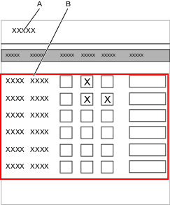
A | Events search window | B | Events list |
All available events are listed in the chapter References. Events have two categories:
Standard events are defined by Atlas Copco and are available in every deliverable.
Custom events are implemented by Atlas Copco on customer request and are only valid and available for specific customers.
Event Configuration
Select a controller in the Plant structure workspace
.Go to the Settings
tab and select Events.Search for a specific event using the search window or expand the sections by selecting them and scrolling through the Events to find the desired event codes.
Select or deselect one or more of the following:
Acknowledge, if the event is to be displayed and acknowledged by the operator.
Log, if the event is to be displayed, written to the log file and shown in the Events
 tab.
tab.
Display, if the event is to be displayed on a screen.
The Details field can be used to write customer specific comments.
When ready, push the changes to the specific controller.
Repeat steps 3 - 5 for every controller that shall be configured.
Event code numbers 0000-7999 are standard events.
Event code numbers 8000-9999 are customer-specific events.
Adding Events to the Library
Select Settings
, then in the Events configuration tab select Manage. Choose Add to Library from the drop-down list.The Create global configuration dialog window opens containing two configuration options:
Auto revert, set as default.
Unlink
Select Create, the event configuration is now locked and visible in the Global Event Library.
Action | Result |
|---|---|
Auto revert | Updating the events through the controller GUI or the web GUI are ignored, if the program is marked as a global event in ToolsTalk 2. The update is made and sent back to ToolsTalk 2 where the change is recognized but not acknowledged. The original global event program is then immediately pushed back to the controller. |
Unlink | Updating the events through the controller GUI or the web GUI causes the program to change from a global event to a local event, in the affected controller. The update is made and sent to ToolsTalk 2 where the change is recognized. As a result the event is immediately removed from the distribution list to the controller. |
The selection of auto revert or unlink must be made when a global event is configured for distribution to a controller. The selection cannot be changed at a later stage.
Working with the Sources Tab
Controller features, such as the Low Reaction Tightening Strategies and controller-wide functions among others, require licenses distributed through the Functionality Management System (FMS). Whereas configuration of features is possible without specific licenses, the assignment and use of those features will require the correct license to be installed on the controller. Please refer to Licenses (FMS) for more detailed information on licenses.
The selection of a task is done in the Task menu in the Virtual station configuration workspace.
External signals used as tasks for tightenings are configured in the Sources  tab. Sources are accessories, or similar, connected to a virtual station. Two types of source tasks are available:
Source Tightening task
Source Batch task
Source Tightening is used to select a single tightening program.
Source Batch is used to select a batch sequence, a series of tightening programs.
Source Tightening Overview
The tightening menu shows a list of Source Batch and Source Tightening configurations. Separate lists can be linked to a Virtual Station by going to the Virtual Station in question, and in the Task properties selecting Choose. There, a Source can be chosen as a task. Source tightenings link a specific tightening program to an identifier number. When the identifier number is sent to the controller, the linked program will run over and over until a different signal is sent ..
Parameter name | Description |
|---|---|
Name | The name issued to the Source Tightening. |
Description | The description of the Source Tightening. |
Lock tool on batch sequence complete | On: The tool is locked when the batch sequence is completed. Off: The tool remains unlocked when the batch sequence is completed. |
Socket selector | Control: When set to Control, an external source selects a tightening program by requesting an identifier number. The identifier number is linked to a corresponding socket in the socket selector, and by lifting the socket the tightening program is selected Confirm: In Confirm mode, the socket selector cannot be used as a controlling source. In this mode identifier numbers are linked to both a tightening program and a specific socket (indicated in an additional column in the list). When an identifier number is requested (by an external signal), the corresponding socket is prompted in the socket selector and the tightening program is activated when the operator lifts the socket (other sockets are disabled). If no socket is specified (that is, set to 0 in the Socket column), the tightening program is activated directly and the socket status is ignored. |
Increment on NOK | On: The batch will advance even if a NOK tightening is performed. Off : Set Max consecutive NOK for the tightening. The batch will only advance if a successful tightening is performed. |
Max consecutive NOK | Set the number of consecutive NOK results to be allowed. If the value is set to 0, then there is no check performed for NOK tightenings. When reaching max consecutive NOK's, the controller locks the tool and the sequence execution is halted. |
Batch control | Select how the source tightening is to be executed. Internal: Configure how many times a source tightening should be repeated. External: Configure how many times a source tightening should be executed by using Open protocol or Fieldbus. Any configuration change clears the source tightening to start over from a clean and known state (the batch count in the batch will be reset to 0). Ongoing tightenings are able to finish before the changes take effect. |
Command | Description |
|---|---|
Add | Adds a new row with lowest identifier available. |
Delete | Removes selected tightening program from the list. Select the tightening program by selecting the corresponding check box. |
Creating a Source Tightening
Select a controller in the Plant structure workspace
.Go to the Sources
tab.Select Add, the Create new source configuration dialog window opens. Choose Tightening from the drop-down menu then select Add.
Issue the Source Tightening with a name.
Select the correct Socket selector (Control or Confirm, depending on what is required).
Set the number of Max consecutive NOK results to be allowed. If the value is set to 0, then there is no check performed for NOK tightenings. When reaching max consecutive NOK's, the controller locks the tool and the sequence execution is halted.
Select which Batch Control is to be used from the drop-down menu.
Internal batch control: Configure how many times a source tightening should be repeated.
External batch control: Configure how many times a source tightening should be executed by using Open protocol or Fieldbus. Any configuration change clears the source tightening so to start over from a clean and known state (the batch count in the batch will be reset to 0). Ongoing tightenings are able to finish before the changes take effect.
By default, only one editable Identifier number will be available when creating a new Source Tightening. Select Add to add more.
Give every item an identifier number
If a socket selector is used, the identifier numbers will correspond to the positions in the socket selector. For example, Identifier number 1 corresponds to socket number 1 in the socket selector.
Choose a tightening program to link to each identifier number by selecting Program and choosing from the list of tightening programs.
Creating a Source Batch
Select a controller in the Plant structure workspace
.Go to the Sources
tab.Select Add, the Create new source configuration dialog window opens. Choose Batch from the drop-down menu then select Add.
Issue the Source Batch with a name
Set the Abort on new identifier to Yes if scanning a new identifier string should abort the previous scan.
Select the Identifier method (String for text, or Number for numerical strings).
Set Free order to On if the strings can be scanned in any order.
Identifier strings can be made up of up to 4 different strings. When free order is set to No, the strings need to be scanned in a specific order for the system to recognize the string.
An error may occur when Free order is set to On, and the lengths of the different strings are duplicated. The scanned sequence will then not activate a tightening program. To remedy this error, set Free order to Off, or adjust the string lengths.
Issue the string a Name and enter the length of the string. (For further information on concatenating strings, see Relevant Information in the User Guide).
Significant positions - the relevant positions in the string. (For further information on Significant Positions, see Relevant Information in the User Guide).
Saved positions - which positions are to be logged by the system. (For further information about Saved Positions, see Relevant Information in the User Guide).
Indicate which strings (in the String contains column) should be linked to which Batch sequence (in the Activates column). Select Add to add more strings.
Wildcards can be used when typing the "string contains". The wildcard(s) can be used at any position in the string. No Batch sequence is activated in case of an ambiguous matching result.
The wildcard is a . (period)
The Abort on new identifier controls how a second signal should be interpreted when a batch sequence has been activated and is ongoing.
If identifier numbers are used in the Batch sequence configuration , the input signal or the socket selector can be used to select a batch within a batch sequence.
The controller can be configured to select a batch sequence with input signal based on either an identifier number or an identifier string.
Significant Positions
Significant positions are used to specify which characters in the barcode string to read when putting together the string to match with your pre-defined string. The number of significant positions must match the number of characters in the pre-defined strings.
Configuring Significant Positions to Read in Barcode String
The positions in the barcode string are associated with a number between 1 and 1024. The first position of the string is 1 and the last is 1024.
Description | Significant positions | Valid configuration | Barcode string to match with pre-defined string |
|---|---|---|---|
Significant positions in order | 1,2,3,7,8 | Ok | ABCGH |
Significant positions in optional order | 7,1,2,3,8 | Ok | GABCH |
Range of numbers | 1–3,7-8 | Ok | ABCGH |
Combining Identifier Strings
The identifier string that is used for matching is a combination of up to four strings from a factory management system or up to four scanner inputs that need to be combined into one string.
The Add and Delete command buttons manage how many strings are combined. The following parameters are available:
Parameter | Description |
|---|---|
Check box | Select an entry if it is to be deleted. |
Name | The string must be given a name. |
Length | The length of the string must be known and must be entered. This is important to be able to combine the correct string identifier. |
Significant positions | The comma-separated positions or ranges (separated by hyphen) in the combined string that are used for matching. |
Saved positions | The comma-separated positions or ranges in the strings that will be saved in the result. |
If more than one identifier string is to be used, perform the following steps:
Press the Add command button to create a new entry in the table.
Issue the string a name.
Enter the length of the string.
Repeat steps 1-3 for every string to be added. Up to four strings can be combined.
The Start-End parameters in each row define the individual string positions in the combined string identifier that is used in the next step of the matching process.
The first part in the task selection process using an identifier string as an input, is to define which positions in the string that are to be activated:
Enter the significant positions, to define which positions in the identifier string will be used for matching. The positions must be either comma-separated, or by range.
Saved Positions
Saved positions is a field where the user can indicate which parts of each string used in the Source Batch will be saved, and how they will be represented in the log. In this field, indicate the positions in the string that need to be saved. Positions can constitute only parts of the entire string. If the field is left empty, the entire (concatenated) string will be saved. The table below shows some examples of saved position combinations.
Saved position values are comma-separated (without spaces), and ranges are indicated using a hyphen.
Identifier string | Positions |
|---|---|
String 1: 1234567 | 1-7 |
String 2: abcdef | 8-13 |
String 3: GHIJKL | 14-19 |
String 4: 890 | 20-22 |
Saved positions | Saved results |
|---|---|
(empty) | 1234567abcdefGHIJKL890 |
1-3,9,11,15,20-22 | 123bdH890 |
8-12,1-7,19,20-21 will be changed automatically to: 1-12,19-21 | 1234567abcdeL89 |
Copying and Pasting a Source Batch or a Source Tightening
Existing Source batches or Source tightenings can be copied and pasted on the same controller, or copied from one controller and then pasted to another.
Copy and Paste are only possible if they are performed on the same controller, or different controllers of the same type and running the same software version.
When you copy an existing Source batch or a Source tightening, any programs and modes associated with the tightening or batch sequence are also copied. These configurations are only copies and can be changed as per requirements.
On the menu bar, select the Sources
tab. The workspace displays a list of available Source batches and Source tightenings.Copy a Source batch or source tightening by either:
Right-clicking on the Source batch or Source tightening to copy, and then choose Copy from the menu.
Or select multiple Source batches or Source tightenings by checking the check boxes in front of each row, right-clicking, and then choose Copy from the menu.
In the Plant Structure
, select the controller to paste the Source to. On the menu bar, select the Sources
tab, and then right-click anywhere in the workspace area and select Paste.
The new Source batch or Source tightening will be issued the first free position in the sequence list. If there are no free slots it will be placed at the bottom of the list and assigned the lowest available index number. It is not possible to change the index number.
Exporting a Source Batch or a Source Tightening
A Source batch or Source tightening can be exported from one controller and imported to another.
Export and Import are only possible if they are performed on the same controller, or different controllers of the same type and running the same software version.
When you export an existing Source batch or a Source tightening, any programs and modes associated with the tightening or batch sequence are also exported. These configurations are only copies and can be changed as per requirements.
In the Plant structure
, select a controller from the list.On the menu bar, select the Sources tab
. The workspace displays a list of all the current Source batches and Source tightenings.Select the check box of the Source batch or tightening to be exported.
Select Manage, and then choose Export from the drop-down menu.
A browser window opens for saving the export file.
The default file name is <SourceBatch>.json or <SourceTightening>.json , the exported file can be given any name with the *.json extension.
Select Save.
Importing a Source Batch or a Source Tightening
A Source batch or Source tightening can be exported from one controller and imported to another.
Export and Import are only possible if they are performed on the same controller, or different controllers of the same type and running the same software version.
When you import an existing Source batch or a Source tightening, any programs and modes associated with the tightening or batch sequence are also imported. These configurations are only copies and can be changed as per requirements.
In the Plant structure
, select a controller from the list.On the menu bar, select the Sources tab
. The workspace area shows a list of all the current Source batches and Source tightenings.Select the Add command button and select Import.
Select Open File and browse to select the relevant .json file.
Select Add.
The new Source batch or Source Tightening will be issued the first free position in the sequence list. If there are no free slots it will be placed at the bottom of the list and assigned the lowest available index number. It is not possible to change the index number.
Working with the StepSync System
With the StepSync function, it is possible to connect several Power Focus 6000 Controllers together and run synchronized tightenings. The first controller in the configuration is called the Sync Reference and handles all the tightening and data reporting. Power Focus 6000 controllers are then connected to this via a cable and are called Sync Members, their only function is to handle the tools.
Sync Reference
The Sync Reference controller is the brain in the system. It handles the tightening settings and all data reporting. It also handles the configuration for the complete system and the connection to ToolsTalk 2 and ToolsNet. All accessories or fieldbuses are connected directly to the Sync Reference
Sync Member
The Sync Member controller works as a dummy drive. The IT part is not running and it is not possible to connect any external accessories or protocols to a Sync Member. Each Sync Member has a channel number assigned to it (2-6). The channel number is used to identify the tool and drive within the Hardware Layout Configuration, and also for result reporting. It is also used in error events to make it possible to identify the faulty part.
Tightenings
It is only possible to run Multistep tightening programs. To be able to synchronize between each tool, synchronization points are used. At these points, the tools will wait for each other before continuing with the next step in the tightening program. A tightening program can contain up to 10 steps (not counting the synchronization points). No repair or termination paths are allowed.
Licensing
The StepSync function is an FMS feature. It is only the Sync Reference that requires a license, making it possible to change any PF6000 Controller into a Sync Member without any additional licenses. The Sync Reference license is an add-on FMS controller feature.
If the Sync Reference license is removed, the system will continue to operate without interruptions. It is still possible to run production, but once every hour the controller will check for a valid Sync Reference license. If no license is found, an error message, that must be acknowledged by the user, will be shown on the GUI.
Controller features, such as the Low Reaction Tightening Strategies and controller-wide functions among others, require licenses distributed through the Functionality Management System (FMS). Whereas configuration of features is possible without specific licenses, the assignment and use of those features will require the correct license to be installed on the controller. Please refer to Licenses (FMS) for more detailed information on licenses.
Hardware Configuration [TT2]

Offline programming of a Hardware Layout Configuration is made in the Controller Template Library.
Configuration Area
In the configuration area you can either create a Hardware Layout Configuration from scratch, or extract an existing configuration from a controller by using the Extract button.
Extract | Updates the hardware layout configuration according to the hardware connected to the controller. |
Zoom in | Zooms in on the layout. (Ctrl + mouse wheel forward) |
Zoom out | Zooms out on the layout. (Ctrl + mouse wheel backward) |
Fit to screen | Reverts the layout back to a default size. |
Delete | Deletes the selected item. |
Controllers
There are two types of controllers:
PF6000 Sync Reference
PF6000 Sync Member
A maximum of 5 Sync Member controllers can be added to a hardware layout configuration. The Sync Reference controller is always the first, the Sync Member controllers and tools need to be added after this.
Tool Box
The Tool Box contains the two controller types and all the tools which are supported. There is a drop-down list to be able to filter on specific tool types.
Only the supported tools, seen in the table below, can be added to the Hardware Layout Configuration from the Tool Box. Unsupported tools connected to a StepSync controller will be displayed with a Tool not supported icon in the Hardware Layout Configuration. These tools will be shown in ToolsTalk 2 in their current position within the StepSync configuration and this position cannot be changed in the Hardware Layout Configuration workspace. If the unsupported tool is deleted from this workspace, the user can Push the configuration to the controller to add the tool before continuing with the Hardware Layout Configuration setup.
The tools can only be added to a controller that doesn't already have a tool connected.
Tool Family | Supported Models |
Tensor STR | ETV, ETD, ETP |
Tensor ST | ETV, ETD, ETP |
Tensor SL | ETV, ETD, ETP, ETF |
Tensor SR | ETV, ETD, ETP |
QST | All (Excluding Dual Transducer - CTT, CTA, CTTA) |
Symbols
Symbols indicate status of each product. If needed, you can point to an indicator to get a tooltip.
| Warning |
| Not expected |
| OK |
| Not synced with controller |
| Wrong type |
| Missing |


Creating a Hardware Layout Configuration
A new installation of a PowerFocus 6000 StepSync system does not contain any previous hardware layout configurations. Each time you connect ToolsTalk 2 to a StepSync controller and the Hardware layout Configuration is empty you will need to either create a new configuration, or extract the current controller hardware setup.
To create a hardware layout configuration, you must first start with a PF6000 Sync Reference controller from the Tool Box.
Start by dragging a Sync Reference controller to the Drop here area and drop it. Indicators are displayed after it has been dropped and you can point to a symbol to get a tooltip.
Add Sync Member controllers to a Sync Reference controller.
Add one of the available tools from the Tool Box to each controller. When pointing to a target controller with a tool, the target controller will change color:
Red: invalid drop
Blue: valid drop
To move, select and drag the product.
To copy, press Ctrl and drag the product.
To delete, choose the product, or hold Ctrl and select many, and then press Delete. A Sync Reference controller with connected Sync Members and tools can only be deleted when it is the single remaining product, or when all other products are deleted simultaneously.
After creation, push the changes to the controller. The hardware deployment status will change after validation.
Status
When the Sync Reference controller is connected and online and the hardware layout configuration is in sync with the controller, ToolsTalk 2 will start to receive notifications about changes in the hardware deployment status. Once notified, ToolsTalk 2 will ask the controller for the Hardware measurement data.
To see detailed deployment status and measurement data:
Select the product in the configuration area. Multiple products can be selected by pressing Ctrl and then selecting.
Click on the Status bar to expand the window.
Tool configurations: Choose a configuration from the drop-down menu.
Inhibit mode: If there is something wrong with the channel (Controller or tool), inhibit mode can be set to continue using your hardware:
False: Channel is running OK.
Report OK: Channel is disabled and reports OK in result.
Report NOK: Channel is disabled and reports NOK in result.
Report No Result: Channel is disabled and does not show up in the result.
State: Text and symbols display the present state
Health: Text and symbols display the present health
Tips:
The height of panel can be increased by dragging the top border.
To get the latest measurement data, select Refresh.
The details displaying the Health status can be expanded to view more information. Select Show only NOK to only view the data with NOK results.
Extracting a Hardware Layout Configuration
If the Hardware Layout Configuration is empty, a current controller setup can be extracted by using the Extract button.
Select Extract, the Extract Hardware Configuration dialog box opens.
Select OK to extract the current configuration.
After extracting, push the changes to the controller in order to receive status and health. The hardware deployment status will change after validation.
The Extract function is not available when creating a Hardware Layout Configuration as a Template.
Sync Mode

Sync Mode is used in conjunction with a Multistep Tightening Program. To run a tightening, a Sync Mode must be created. The Sync Mode specifies the channels to use in the tightening and also the tightening program to be used for each channel. Up to 100 different Sync Modes can be created. It is not possible to use different tightening programs for different channels, they must always run the same tightening program. The Sync Mode feature allows you to set up a mode for each configuration.
It is used for configuring:
The tools that shall be included in a synchronized tightening.
Specifying the tightening program each tool shall run.
Handling reject management.
Configuring the bolt configuration
Each line in the workspace represents one Sync Mode and each Sync Mode has a name and an index. To run a tightening the required Sync Mode index is selected, for example with a fieldbus signal. In a production line a different Sync Mode may be needed for each new product. The columns contain the following information:
Column | Description |
|---|---|
Check box | Used for example when deleting a Sync Mode. |
Name | A user defined name for the Sync Mode. |
Channels | The number of channels in the Sync Mode. |
Last saved | Time expressed in ToolsTalk 2 time. |
Last saved by | Shows which user saved the configuration data. |
Controller updated | Time when the controller was updated, expressed in controller time. |
Controller updated by | Shows which user last updated the controller. |
Reject Management
In the case of a NOK tightening (due to monitor or restriction errors) it is possible to specify the action for the remaining channels. Either the complete tightening is ended, with the status NOK for all channels, or the channels without error continue to run the remaining steps in the program.
Double-click on an existing Sync Mode to view/adjust the following parameters:
Reject Management
Action if failure | Description |
End all |
|
Continue OK |
|
Bolt Configuration
For each channel there is an associated bolt number. The bolt number is automatically set to the same value as the Channel number and is not possible to edit. An optional bolt name can also be given for each channel.
Parameter | Description |
|---|---|
Check box | Used for example when deleting a channel. |
Channel | Channel number, also named drive index. |
Tightening program | Select tightening program defined in the menu Tightening Program. |
Bolt | Bolt number is not editable and automatically takes the channel number value. This number will be used as the address when collecting data for the specific bolt, for example, in the fieldbus signal Bolt tightening status. |
Bolt name (optional) | Name of the bolt. |
If a tightening program of one bolt configuration is changed, all other bolt configurations in the same Sync Mode take the newly selected bolt configuration.
- Adding a Sync Mode
- Handling Tightening Sync Mode Configuration
- Handling Loosening Sync Mode Configuration
- Running a Loosening Sync Mode Using the Input Select Loosening
- Running a Loosening Sync Mode Using Input Start Loosening
- Copying and Pasting a Sync Mode
- Exporting a Sync Mode
- Importing a Sync Mode
- Deleting a Sync Mode
Adding a Sync Mode
In the Plant Structure
window, select a controller from the list.On the Menu bar, select the Sync Mode
tab. The workspace area shows a list of all the current sync modes. Select the Add command button. The Create a new Mode dialog box opens.
Issue the new Sync Mode with a name and optionally an index number.
In Operation mode, choose Tightening.
Select Add to add the new Sync Mode.
In Properties, issue the Sync Mode with a description and select the relevant Loosening Program from the drop-down list.
In Reject Management, choose an Action if failure from the drop-down list.
End all
Continue OK
To add the bolt configuration, click ADD or ADD MANY. You can have a maximum of 64 bolt configurations.
Choose the relevant Tightening Program from the drop-down list.
Select Sync Mode in the breadcrumbs to return to the list.
The list is updated and the new sync mode is added at the lowest possible position.
In the Plant Structure
window, select a controller from the list.On the Menu bar, select the Sync Mode
tab. The workspace area shows a list of all the current sync modes. Select the Add command button. The Create a new Mode dialog box opens.
Issue the new Sync Mode with a name and optionally an index number.
In Operation mode, choose Loosening.
Select Add to add the new Sync Mode.
In Properties, issue the Sync Mode with a description.
To add the bolt configuration, click ADD or ADD MANY. You can have a maximum of 64 bolt configurations.
Choose the relevant Tightening Program from the drop-down list.
Select Sync Mode in the breadcrumbs to return to the list.
The list is updated and the new Sync Mode is added at the lowest possible position.
Handling Tightening Sync Mode Configuration
Double-click on a tightening Sync Mode to configure that Sync Mode.
Properties
Parameter | Description |
|---|---|
Name | A user defined name for the mode. |
Description | Description of the mode. |
Referencing Loosening Sync Mode
A tightening Sync Mode can be linked to a loosening Sync Mode. Referencing a loosening sync mode is located in the Properties menu of a tightening Sync Mode
Select the relevant loosening Sync Mode from the Loosening Sync mode drop-down.
The number of bolt configurations and the channel numbers used in the bolt configurations of the tightening Sync Mode should be the same as the loosening Sync Mode selected and a warning is displayed if they differ.
Reject Management
Action if failure | Description |
End all |
|
Continue OK |
|
Bolt configuration
To add bolt configurations, click ADD or ADD MANY. You can have maximum of 64 bolt configurations.
Parameter | Description |
|---|---|
Check box | Used when, for example, deleting a channel. |
Channel | Number of the channel, also named drive index. |
Tightening program | Select tightening program defined in the menu Tightening Program. |
Bolt | The actual fastener that is tightened when a tightening is made. This number will be used as the address when collecting data for the specific bolt, for example, in the fieldbus signal Bolt tightening status. |
Bolt name (optional) | Name of the bolt. |
Handling Loosening Sync Mode Configuration
Double-click on a loosening Sync Mode to configure that Sync Mode.
Parameter | Description |
|---|---|
Name | A user defined name for the mode. |
Description | Description of the mode. |
Bolt Configuration
The bolt configuration of a loosening Sync Mode can only be linked to a loosening multistep program and only lists the available loosening multistep programs.
To add bolt configurations, click ADD or ADD MANY. You can have maximum of 64 bolt configurations.
Parameter | Description |
|---|---|
Check box | Used when, for example, deleting a channel. |
Channel | Number of the channel, also named drive index. |
Loosening program | Select the loosening multistep program defined in the menu Tightening Program. |
Running a Loosening Sync Mode Using the Input Select Loosening
Select a tightening sync mode with an associated loosening sync mode.
This can be done by adding the I/O signal Select Input, Id 10020 in the To controller area in the Fieldbus sub-tab under Fieldbus and SoftPLC
or this can also be done by selecting a task in the Task under the Virtual Station tab .
Select loosening using the I/O signal Select loosening, Id 10029 in the To controller area in the Fieldbus sub-tab under Fieldbus and SoftPLC
.Start the loosening using any of the two signals:
Start drive (continuos), Id 10028
Start drive (pulse), Id 10113
Running a Loosening Sync Mode Using Input Start Loosening
Select a tightening sync mode with an associated loosening sync mode
This can be done by adding the I/O signal Select Input, Id 10020 in the To controller area in the Fieldbus sub-tab under Fieldbus and SoftPLC
or this can also be done by selecting a task in the Task under the Virtual Station tab .
Start the loosening using any of these two signals:
Start loosening (continuous), Id 10011
Loosening pulse start (pulse), Id 10072
Copying and Pasting a Sync Mode
Existing Sync Modes can be copied and pasted on the same controller, or copied from one controller and then pasted to another.
Copy and Paste are only possible if they are performed on the same controller, or different controllers running the same software version and controller type.
On the menu bar, select the Sync Mode
tab. The workspace displays a list of available Sync Modes.Copy the Sync Mode by either:
Right-click the Sync Mode to copy, and then choose Copy from the menu.
Or select multiple Sync Modes by checking the check box in front of each row, right-click, and then choose Copy from the menu.
In the Plant Structure
, select the controller to paste the Sync Mode to. On the menu bar, select the Sync Mode
tab, and then right-click anywhere in the workspace area and choose Paste. The pasted Sync Mode is added to the first available position in the list.
If there are no available slots then the Sync Mode will be added to the bottom of the list and assigned the lowest available index number. It is not possible to change the index number to rearrange the order. (This operation is valid only for tightening Sync Mode )
When pasting a Sync Mode, the connected Multistep Tightening Programs are also included. The loosening Sync Mode connected to that Multistep Tightening program is not copied by default. If there is no space to import the Multistep Tightening programs, because the maximum number has already been reached, then the whole paste operation will fail.
Exporting a Sync Mode
A Sync Mode can be exported from one controller and imported to another.
Export and Import are only possible if they are performed on the same controller, or different controllers running the same software version and controller type.
In the Plant structure
, select a controller from the list.On the menu bar, select the Sync Mode
tab. The workspace area displays a list of all the current Sync Modes.Select the check box of the Sync Mode to be exported.
Select Manage, and then choose Export from the drop-down menu.
A browser window opens for saving the export file.
The default file name is <SyncModeName>.json, the exported file can be given any name with the *.json extension.
Select Save.
Importing a Sync Mode
A Sync Mode can be exported from one controller and imported to another.
Export and Import are only possible if they are performed on the same controller, or different controllers running the same software version and controller type.
In the Plant structure
, select a controller from the list.On the menu bar, select the Sync Mode
tab. The workspace area displays a list of all the current Sync Modes. Select the Add command button and select Import.
Select Open File and browse to select the relevant .json file.
Select Add.
When importing a Sync Mode, the connected Multistep Tightening Programs are also included. If there is no space to import the Multistep Tightening Programs, because the maximum number has already been reached, then the whole import operation will fail.
Deleting a Sync Mode
In the Plant Structure
window, select a controller from the list.On the Menu bar, select the Sync Mode
tab. The workspace area shows a list of all the current sync modes. For each Sync Mode to be deleted, mark the check box in the left most column in the workspace area.
Select the Manage command button, and then Delete from the drop-down list. The selected Sync Mode is removed and the list is updated.
Step Sync Signals
The StepSync system supports the same I/O signals listed in the tables below. These can be mapped in fieldbus configuration and accessory configuration. Some are also available through Open Protocol.
Input Signals
Abort Sequence - 10012
When a Batch sequence abort request is received, the Batch sequence functionality aborts the batch sequence only after getting the ongoing tightening result.
Name in SoftPLC: ABORT_BATCH_SEQUENCE
Signal Type | Value Type | Size Min [bit] | Size Max [bit] |
|---|---|---|---|
Event | Boolean | 1 | 1 |
Devices
Fieldbus: TRUE
Indicator Box: FALSE
Internal I/O: TRUE
Operator Panel: TRUE
Tool Functions: TRUE
ST Selector: FALSE
Stacklight: TRUE
TLS Tag: FALSE
I/O Expander: TRUE
Batch Decrement - 10002
Incrementally decreases the batch counter by one.
Name in SoftPLC: BATCH_DECREMENT
Signal Type | Value Type | Size Min [bit] | Size Max [bit] |
|---|---|---|---|
Event | Boolean | 1 | 1 |
Devices
Fieldbus: TRUE
Indicator Box: FALSE
Internal I/O: TRUE
Operator Panel: TRUE
Tool Functions: TRUE
ST Selector: FALSE
Stacklight: TRUE
TLS Tag: FALSE
I/O Expander: TRUE
Batch Increment - 10001
Incrementally increases the batch counter by one.
Name in SoftPLC: BATCH_INCREMENT
Signal Type | Value Type | Size Min [bit] | Size Max [bit] |
|---|---|---|---|
Event | Boolean | 1 | 1 |
Devices
Fieldbus: TRUE
Indicator Box: FALSE
Internal I/O: TRUE
Operator Panel: TRUE
Tool Functions: TRUE
ST Selector: FALSE
Stacklight: TRUE
TLS Tag: FALSE
I/O Expander: TRUE
Bypass Tightening Program - 10008
Skips the next tightening program in the running batch sequence.
Name in SoftPLC: BYPASS_PSET
Signal Type | Value Type | Size Min [bit] | Size Max [bit] |
|---|---|---|---|
Event | Boolean | 1 | 1 |
Devices
Fieldbus: TRUE
Indicator Box: FALSE
Internal I/O: TRUE
Operator Panel: TRUE
Tool Functions: TRUE
ST Selector: FALSE
Stacklight: TRUE
TLS Tag: FALSE
I/O Expander: TRUE
Channel Command - 10054
Name in SoftPLC: CHANNEL_COMMAND
Signal Type | Value Type | Size Min [bit] | Size Max [bit] |
|---|---|---|---|
State | uint32 array | 1 | 32 |
Devices
Fieldbus: TRUE
Indicator Box: FALSE
Internal I/O: TRUE
Operator Panel: TRUE
Tool Functions: TRUE
ST Selector: FALSE
Stacklight: TRUE
TLS Tag: FALSE
I/O Expander: TRUE
This signal contains subsignals, refer to Subsignals - Input for all the subsignals.
Disable Fieldbus - 10049
Disables the fieldbus.
Name in SoftPLC: DISABLE_FIELDBUS
Signal Type | Value Type | Size Min [bit] | Size Max [bit] |
|---|---|---|---|
State | Boolean | 1 | 1 |
Devices
Fieldbus: FALSE
Indicator Box: FALSE
Internal I/O: TRUE
Operator Panel: TRUE
Tool Functions: FALSE
ST Selector: FALSE
Stacklight: TRUE
TLS Tag: FALSE
I/O Expander: TRUE
Disable Test Bolt - 10057
Name in SoftPLC: DISABLE_TESTBOLT
Signal Type | Value Type | Size Min [bit] | Size Max [bit] |
|---|---|---|---|
State | Boolean | 1 | 1 |
Devices
Fieldbus: TRUE
Indicator Box: FALSE
Internal I/O: TRUE
Operator Panel: TRUE
Tool Functions: FALSE
ST Selector: FALSE
Stacklight: TRUE
TLS Tag: FALSE
I/O Expander: TRUE
Disable tool - 30000
If the signal is set to True, a tool is immediately stopped and locked.
Converter | Signal Type | Value Type | Size Min [bit] | Size Max [bit] |
|---|---|---|---|---|
Standard | State | Boolean | 1 | 1 |
Invert | State | Boolean | 1 | 1 |
Devices
Fieldbus: TRUE
Indicator Box: FALSE
Internal I/O: FALSE
Operator Panel: FALSE
Tool Functions: FALSE
ST Selector: FALSE
Stacklight: FALSE
TLS Tag: FALSE
I/O Expander: FALSE
To avoid duplicating signals, it is possible to define Value Converters.
Converters are used to support more than one representation of the same signal (for example Angle/Torque Status can both be represented bitwise or as a status character).
Dynamic Batch Size - 10074
Name in SoftPLC: DYNAMIC_BATCH_SIZE
Signal Type | Value Type | Size Min [bit] | Size Max [bit] |
|---|---|---|---|
State | Integer | 1 | 16 |
Devices
Fieldbus: TRUE
Indicator Box: FALSE
Internal I/O: FALSE
Operator Panel: FALSE
Tool Functions: FALSE
ST Selector: FALSE
Stacklight: FALSE
TLS Tag: FALSE
I/O Expander: FALSE
Enable Operation - 10055
Name in SoftPLC: ENABLE_OPERATION
Converter | Signal Type | Value Type | Size Min [bit] | Size Max [bit] |
|---|---|---|---|---|
Standard | State | Boolean | 1 | 1 |
Invert | State | Boolean | 1 | 1 |
Devices
Fieldbus: TRUE
Indicator Box: FALSE
Internal I/O: TRUE
Operator Panel: TRUE
Tool Functions: FALSE
ST Selector: FALSE
Stacklight: TRUE
TLS Tag: FALSE
I/O Expander: TRUE
To avoid duplicating signals, it is possible to define Value Converters.
Converters are used to support more than one representation of the same signal (for example Angle/Torque Status can both be represented bitwise or as a status character).
Fieldbus AsyncData To PF - 10077
Name in SoftPLC:
Signal Type | Value Type | Size Min [bit] | Size Max [bit] |
|---|---|---|---|
State | uint8 array | 16 | 2048 |
Devices
Fieldbus: TRUE
Indicator Box: FALSE
Internal I/O: FALSE
Operator Panel: FALSE
Tool Functions: FALSE
ST Selector: FALSE
Stacklight: FALSE
TLS Tag: FALSE
I/O Expander: FALSE
Fieldbus Lock Loosening - 20021
A Virtual Station is locked when starting a loosening if the signal is set from a connected and supported accessory.
An ongoing loosening is aborted immediately when Fieldbus Lock Loosening is set to True, due to the Stop Drive setting.
Converter | Signal Type | Value Type | Size Min [bit] | Size Max [bit] |
|---|---|---|---|---|
Standard | State | Boolean | 1 | 1 |
Invert | State | Boolean | 1 | 1 |
Devices
Fieldbus: TRUE
Indicator Box: FALSE
Internal I/O: FALSE
Operator Panel: FALSE
Tool Functions: FALSE
ST Selector: FALSE
Stacklight: FALSE
TLS Tag: FALSE
I/O Expander: FALSE
To avoid duplicating signals, it is possible to define Value Converters.
Converters are used to support more than one representation of the same signal (for example Angle/Torque Status can both be represented bitwise or as a status character).
Fieldbus Lock Tightening - 20020
A Virtual Station is locked when starting a tightening if the signal is set from a connected and supported accessory.
An ongoing tightening is aborted immediately when Fieldbus Lock Tightening is set to True, due to the Stop Drive setting.
Converter | Signal Type | Value Type | Size Min [bit] | Size Max [bit] |
|---|---|---|---|---|
Standard | State | Boolean | 1 | 1 |
Invert | State | Boolean | 1 | 1 |
Devices
Fieldbus: TRUE
Indicator Box: FALSE
Internal I/O: FALSE
Operator Panel: FALSE
Tool Functions: FALSE
ST Selector: FALSE
Stacklight: FALSE
TLS Tag: FALSE
I/O Expander: FALSE
To avoid duplicating signals, it is possible to define Value Converters.
Converters are used to support more than one representation of the same signal (for example Angle/Torque Status can both be represented bitwise or as a status character).
Flush Read Result Queue - 30005
Signal Type | Value Type | Size Min [bit] | Size Max [bit] |
|---|---|---|---|
Event | Boolean | 1 | 1 |
Devices
Fieldbus: TRUE
Indicator Box: FALSE
Internal I/O: FALSE
Operator Panel: FALSE
Tool Functions: FALSE
ST Selector: FALSE
Stacklight: FALSE
TLS Tag: FALSE
I/O Expander: FALSE
Select Input Bit 4 - 10066
Name in SoftPLC: SEL_INPUT_BIT_4
Signal Type | Value Type | Size Min [bit] | Size Max [bit] |
|---|---|---|---|
State | Boolean | 1 | 1 |
Devices
Fieldbus: FALSE
Indicator Box: FALSE
Internal I/O: TRUE
Operator Panel: TRUE
Tool Functions: FALSE
ST Selector: FALSE
Stacklight: TRUE
TLS Tag: FALSE
I/O Expander: TRUE
ID for Dynamic Batch Size - 10073
Name in SoftPLC: DYNAMIC_BATCH_SIZE_TPID
Converter | Signal Type | Value Type | Size Min [bit] | Size Max [bit] |
|---|---|---|---|---|
Standard | State | Integer | 1 | 16 |
TreatZeroAsOne | State | Integer | 1 | 16 |
Devices
Fieldbus: TRUE
Indicator Box: FALSE
Internal I/O: FALSE
Operator Panel: FALSE
Tool Functions: FALSE
ST Selector: FALSE
Stacklight: FALSE
TLS Tag: FALSE
I/O Expander: FALSE
To avoid duplicating signals, it is possible to define Value Converters.
Converters are used to support more than one representation of the same signal (for example Angle/Torque Status can both be represented bitwise or as a status character).
Lock Loosening - 20003
Signal Type | Value Type | Size Min [bit] | Size Max [bit] |
|---|---|---|---|
State | Boolean | 1 | 1 |
Devices
Fieldbus: FALSE
Indicator Box: FALSE
Internal I/O: TRUE
Operator Panel: TRUE
Tool Functions: FALSE
ST Selector: FALSE
Stacklight: TRUE
TLS Tag: FALSE
I/O Expander: TRUE
Lock Tightening - 20002
Tool locked for tightening by digital input.
Signal Type | Value Type | Size Min [bit] | Size Max [bit] |
|---|---|---|---|
State | Boolean | 1 | 1 |
Devices
Fieldbus: FALSE
Indicator Box: FALSE
Internal I/O: TRUE
Operator Panel: TRUE
Tool Functions: FALSE
ST Selector: FALSE
Stacklight: TRUE
TLS Tag: FALSE
I/O Expander: TRUE
Lock Tool Active High - 20004
Signal Type | Value Type | Size Min [bit] | Size Max [bit] |
|---|---|---|---|
State | Boolean | 1 | 1 |
Devices
Fieldbus: FALSE
Indicator Box: FALSE
Internal I/O: TRUE
Operator Panel: TRUE
Tool Functions: FALSE
ST Selector: FALSE
Stacklight: TRUE
TLS Tag: FALSE
I/O Expander: TRUE
Lock Tool Active Low - 20061
Locks the tool when this signal is low.
Signal Type | Value Type | Size Min [bit] | Size Max [bit] |
|---|---|---|---|
State | Boolean | 1 | 1 |
Devices
Fieldbus: FALSE
Indicator Box: FALSE
Internal I/O: TRUE
Operator Panel: TRUE
Tool Functions: FALSE
ST Selector: FALSE
Stacklight: TRUE
TLS Tag: FALSE
I/O Expander: TRUE
Master Unlock - 10005
Unlocks most locks defined in lock page.
Name in SoftPLC: MASTER_UNLOCK
Signal Type | Value Type | Size Min [bit] | Size Max [bit] |
|---|---|---|---|
Event | Boolean | 1 | 1 |
Devices
Fieldbus: TRUE
Indicator Box: FALSE
Internal I/O: TRUE
Operator Panel: TRUE
Tool Functions: TRUE
ST Selector: FALSE
Stacklight: TRUE
TLS Tag: FALSE
I/O Expander: TRUE
Pulse Stop - 10030
If this signal is generated any ongoing tightening or loosening will be stopped. Used in combination with 10024 or 10072.
Name in SoftPLC: TIGHTENING_STOP_PULSE
Signal Type | Value Type | Size Min [bit] | Size Max [bit] |
|---|---|---|---|
State | Boolean | 1 | 1 |
Devices
Fieldbus: TRUE
Indicator Box: FALSE
Internal I/O: TRUE
Operator Panel: TRUE
Tool Functions: FALSE
ST Selector: FALSE
Stacklight: TRUE
TLS Tag: FALSE
I/O Expander: TRUE
Read Result Handshake Ack - 30004
Enable the Read Result Handshake feature in the Fieldbus device for making the controller available for the signal Rear Result Handshake Ack.
Signal Type | Value Type | Size Min [bit] | Size Max [bit] |
|---|---|---|---|
State | Boolean | 1 | 1 |
Devices
Fieldbus: TRUE
Indicator Box: FALSE
Internal I/O: FALSE
Operator Panel: FALSE
Tool Functions: FALSE
ST Selector: FALSE
Stacklight: FALSE
TLS Tag: FALSE
I/O Expander: FALSE
Reset All Identifiers - 10115
In Source batch string used to reset all received string identifiers from string receiving sequence at once. In other worktasks clears VIN number.
Name in SoftPLC: RESET_ALL_IDENTIFIERS
Signal Type | Value Type | Size Min [bit] | Size Max [bit] |
|---|---|---|---|
Event | Boolean | 1 | 1 |
Devices
Fieldbus: TRUE
Indicator Box: FALSE
Internal I/O: TRUE
Operator Panel: TRUE
Tool Functions: TRUE
ST Selector: FALSE
Stacklight: TRUE
TLS Tag: FALSE
I/O Expander: TRUE
Reset Batch - 10003
Resets the batch counter to 0. No batch OK (nxOK). If batch OK is activated, it will be deactivated.
Name in SoftPLC: RESET_BATCH
Signal Type | Value Type | Size Min [bit] | Size Max [bit] |
|---|---|---|---|
Event | Boolean | 1 | 1 |
Devices
Fieldbus: TRUE
Indicator Box: FALSE
Internal I/O: TRUE
Operator Panel: TRUE
Tool Functions: TRUE
ST Selector: FALSE
Stacklight: TRUE
TLS Tag: FALSE
I/O Expander: TRUE
Reset Batch Sequence - 10053
Resets the Batch Sequence. Unlocks a tool that is locked by Tool Lock on Complete.
Name in SoftPLC: RESET_BATCH_SEQUENCE
Signal Type | Value Type | Size Min [bit] | Size Max [bit] |
|---|---|---|---|
Event | Boolean | 1 | 1 |
Devices
Fieldbus: TRUE
Indicator Box: FALSE
Internal I/O: TRUE
Operator Panel: TRUE
Tool Functions: TRUE
ST Selector: FALSE
Stacklight: TRUE
TLS Tag: FALSE
I/O Expander: TRUE
Reset Cycle Status - 10056
Name in SoftPLC: RESET_CYCLE_STATUS
Signal Type | Value Type | Size Min [bit] | Size Max [bit] |
|---|---|---|---|
Event | Boolean | 1 | 1 |
Devices
Fieldbus: TRUE
Indicator Box: FALSE
Internal I/O: TRUE
Operator Panel: TRUE
Tool Functions: FALSE
ST Selector: FALSE
Stacklight: TRUE
TLS Tag: FALSE
I/O Expander: TRUE
Reset Latest Identifier - 10114
In Source batch string used to reset latest received string from string receiving sequence. In other worktasks clears VIN number.
Name in SoftPLC: RESET_LATEST_IDENTIFIER
Signal Type | Value Type | Size Min [bit] | Size Max [bit] |
|---|---|---|---|
Event | Boolean | 1 | 1 |
Devices
Fieldbus: TRUE
Indicator Box: FALSE
Internal I/O: TRUE
Operator Panel: TRUE
Tool Functions: TRUE
ST Selector: FALSE
Stacklight: TRUE
TLS Tag: FALSE
I/O Expander: TRUE
Reset Sequence Status - 10118
Resets signals Batch Sequence Done/OK/NOK and Sequence Aborted.
Name in SoftPLC: RESET_SEQUENCE_STATUS
Signal Type | Value Type | Size Min [bit] | Size Max [bit] |
|---|---|---|---|
Event | Boolean | 1 | 1 |
Devices
Fieldbus: TRUE
Indicator Box: FALSE
Internal I/O: TRUE
Operator Panel: TRUE
Tool Functions: FALSE
ST Selector: FALSE
Stacklight: TRUE
TLS Tag: FALSE
I/O Expander: TRUE
Reset System Error - 10062
Name in SoftPLC: RESET_SYSTEM_ERROR
Signal Type | Value Type | Size Min [bit] | Size Max [bit] |
|---|---|---|---|
Event | Boolean | 1 | 1 |
Devices
Fieldbus: TRUE
Indicator Box: FALSE
Internal I/O: TRUE
Operator Panel: TRUE
Tool Functions: FALSE
ST Selector: FALSE
Stacklight: TRUE
TLS Tag: FALSE
I/O Expander: TRUE
Reset Too Many NOK - 10013
Reset the batch after receiving lock Too Many NOK
Name in SoftPLC: RESET_TOO_MANY_NOK
Signal Type | Value Type | Size Min [bit] | Size Max [bit] |
|---|---|---|---|
Event | Boolean | 1 | 1 |
Devices
Fieldbus: TRUE
Indicator Box: FALSE
Internal I/O: TRUE
Operator Panel: TRUE
Tool Functions: TRUE
ST Selector: FALSE
Stacklight: TRUE
TLS Tag: FALSE
I/O Expander: TRUE
Select Input - 10020
Selects Tightening Program withing Source Tightening/Batch within sequence.
Name in SoftPLC: SELECT_INPUT_VALUE
Converter | Signal Type | Value Type | Size Min [bit] | Size Max [bit] |
|---|---|---|---|---|
Standard | State | Integer | 1 | 16 |
TreatZeroAsOne | State | Integer | 1 | 1 |
Devices
Fieldbus: TRUE
Indicator Box: FALSE
Internal I/O: FALSE
Operator Panel: FALSE
Tool Functions: FALSE
ST Selector: TRUE
Stacklight: FALSE
TLS Tag: FALSE
I/O Expander: FALSE
To avoid duplicating signals, it is possible to define Value Converters.
Converters are used to support more than one representation of the same signal (for example Angle/Torque Status can both be represented bitwise or as a status character).
Select Input and Dynamic Batch Size - 30007
It is used to set the Batch Size for a specific "Identifier Number" in a Source Tightening Task, running "External batch control".
Batch size can be set to 1-250.
If Batch size is set to 0, it is treated as infinite batch. The user is not able to un-set a Batch back to a state where it has no size, once it has been set.
Converter | Signal Type | Value Type | Size Min [bit] | Size Max [bit] |
|---|---|---|---|---|
Standard | State | Integer | 16 | 16 |
TreatZeroAsOne | State | Integer | 16 | 16 |
Devices
Fieldbus: TRUE
Indicator Box: FALSE
Internal I/O: FALSE
Operator Panel: FALSE
Tool Functions: FALSE
ST Selector: FALSE
Stacklight: FALSE
TLS Tag: FALSE
I/O Expander: FALSE
To avoid duplicating signals, it is possible to define Value Converters.
Converters are used to support more than one representation of the same signal (for example Angle/Torque Status can both be represented bitwise or as a status character).
Select Input Bit 0 - 10016
Name in SoftPLC: SEL_INPUT_BIT_0
Signal Type | Value Type | Size Min [bit] | Size Max [bit] |
|---|---|---|---|
State | Boolean | 1 | 1 |
Devices
Fieldbus: FALSE
Indicator Box: FALSE
Internal I/O: TRUE
Operator Panel: TRUE
Tool Functions: TRUE
ST Selector: FALSE
Stacklight: TRUE
TLS Tag: FALSE
I/O Expander: TRUE
Select Input Bit 1 - 10017
Name in SoftPLC: SEL_INPUT_BIT_1
Signal Type | Value Type | Size Min [bit] | Size Max [bit] |
|---|---|---|---|
State | Boolean | 1 | 1 |
Devices
Fieldbus: FALSE
Indicator Box: FALSE
Internal I/O: TRUE
Operator Panel: TRUE
Tool Functions: TRUE
ST Selector: FALSE
Stacklight: TRUE
TLS Tag: FALSE
I/O Expander: TRUE
Select Input Bit 2 - 10018
Name in SoftPLC: SEL_INPUT_BIT_2
Signal Type | Value Type | Size Min [bit] | Size Max [bit] |
|---|---|---|---|
State | Boolean | 1 | 1 |
Devices
Fieldbus: FALSE
Indicator Box: FALSE
Internal I/O: TRUE
Operator Panel: TRUE
Tool Functions: TRUE
ST Selector: FALSE
Stacklight: TRUE
TLS Tag: FALSE
I/O Expander: TRUE
Select Input Bit 3 - 10019
Name in SoftPLC: SEL_INPUT_BIT_3
Signal Type | Value Type | Size Min [bit] | Size Max [bit] |
|---|---|---|---|
State | Boolean | 1 | 1 |
Devices
Fieldbus: FALSE
Indicator Box: FALSE
Internal I/O: TRUE
Operator Panel: TRUE
Tool Functions: TRUE
ST Selector: FALSE
Stacklight: TRUE
TLS Tag: FALSE
I/O Expander: TRUE
Select Input Bit 5 - 10067
Name in SoftPLC: SEL_INPUT_BIT_5
Signal Type | Value Type | Size Min [bit] | Size Max [bit] |
|---|---|---|---|
State | Boolean | 1 | 1 |
Devices
Fieldbus: FALSE
Indicator Box: FALSE
Internal I/O: TRUE
Operator Panel: TRUE
Tool Functions: FALSE
ST Selector: FALSE
Stacklight: TRUE
TLS Tag: FALSE
I/O Expander: TRUE
Select Input Bit 6 - 10068
Name in SoftPLC: SEL_INPUT_BIT_6
Signal Type | Value Type | Size Min [bit] | Size Max [bit] |
|---|---|---|---|
State | Boolean | 1 | 1 |
Devices
Fieldbus: FALSE
Indicator Box: FALSE
Internal I/O: TRUE
Operator Panel: TRUE
Tool Functions: TRUE
ST Selector: FALSE
Stacklight: TRUE
TLS Tag: FALSE
I/O Expander: TRUE
Select Input Bit 7 - 10069
Name in SoftPLC: SEL_INPUT_BIT_7
Signal Type | Value Type | Size Min [bit] | Size Max [bit] |
|---|---|---|---|
State | Boolean | 1 | 1 |
Devices
Fieldbus: FALSE
Indicator Box: FALSE
Internal I/O: TRUE
Operator Panel: TRUE
Tool Functions: TRUE
ST Selector: FALSE
Stacklight: TRUE
TLS Tag: FALSE
I/O Expander: TRUE
Select Input Bit 8 - 10070
Name in SoftPLC: SEL_INPUT_BIT_8
Signal Type | Value Type | Size Min [bit] | Size Max [bit] |
|---|---|---|---|
State | Boolean | 1 | 1 |
Devices
Fieldbus: FALSE
Indicator Box: FALSE
Internal I/O: TRUE
Operator Panel: TRUE
Tool Functions: TRUE
ST Selector: FALSE
Stacklight: TRUE
TLS Tag: FALSE
I/O Expander: TRUE
Select Input Bit 9 - 10071
Name in SoftPLC: SEL_INPUT_BIT_9
Signal Type | Value Type | Size Min [bit] | Size Max [bit] |
|---|---|---|---|
State | Boolean | 1 | 1 |
Devices
Fieldbus: FALSE
Indicator Box: FALSE
Internal I/O: TRUE
Operator Panel: TRUE
Tool Functions: TRUE
ST Selector: FALSE
Stacklight: TRUE
TLS Tag: FALSE
I/O Expander: TRUE
Select Loosening - 10029
Selects loosening as default operation mode and used in combination with Start Tools -10028 signal.
Name in SoftPLC: SELECT_LOOSENING
Signal Type | Value Type | Size Min [bit] | Size Max [bit] |
|---|---|---|---|
State | Boolean | 1 | 1 |
Devices
Fieldbus: TRUE
Indicator Box: FALSE
Internal I/O: TRUE
Operator Panel: TRUE
Tool Functions: FALSE
ST Selector: FALSE
Stacklight: TRUE
TLS Tag: FALSE
I/O Expander: TRUE
Select Next Identifier Number - 10116
It is possible to use the signal Select Next Identifier Number when a task in the virtual station is configured as:
Batch Sequence
Source Tightening
Source Batch
Number Identifier method
String Identifier method
ST Selector configurable functions Take Next and Take Previous enable the input signals Select Next Identifier Number and Select Previous Identifier Number.
Batch Sequence selected as Virtual Station Task
If Free Order switch has been enabled, the signal Select Next Identifier Number can select different batches within the selected sequence.
Before selecting batches, it is mandatory that they have the identifier number assigned. If a batch does not have the identifier number assigned, the signal Select Next Identifier Number cannot select it, even if Free Order switch is enabled.
It enables looping through the batches that have a configured identifier number.
If identifier number is "None", it is possible to select it only after all Batches with configured identifier number are completed.
It is possible to do looping, but 0 is skipped. When a batch is finished, it is no longer selectable.
For example, in case of batches with assigned identifier numbers 1,2,4,5, the signal runs in loop: 1,2,4,5,1,2,4... as long as the batches are not finished.
Source Tightening selected as Virtual Station Task
The signal selects the next identifier number from the list of tightening programs specified in the Source Tightening task.
The selection runs from the currently selected identifier number to the next larger one.
When the biggest identifier number is selected, this signal selects 0; after 0, the signal selects the next bigger identifier number.
If 0 is selected as identifier number, the tool is locked.
If the identifier number has been added to the Source Tightening list, but no tightening program has ever been assigned to it, it is skipped while looping through the Source Tightening list.
If the tightening program is assigned to an identifier number and then it is removed from the list of tightening programs, it is still possible to select this identifier number. In this case, the tool is locked because there is not a specific tightening program.
When Selector Mode switch is set to Confirm, the socket selector needs to be assigned and configured. All tightening programs can be selected, but before running them, appropriate socket must be lifted from the socket selector.
Source Batch selected as Virtual Station Task
In Sources > Batch Sequence > Source Batch, when the identifier method is set to Number, the signal Select Next Identifier Number selects sequences from a list of sequences shown in Source Batch task.
It is possible to do looping through 0. The signal Select Next Identifier Number selects only the identifier numbers assigned to sequences.
For example, if there are 4 sequences available with identifier numbers 1,2,4, and 8, the signal Select Next Identifier Number iterates and selects 1,2,4,8,0,1,2...
The identifier numbers not defined are not selected.
In Sources > Batch Sequence > Source Batch, when the identifier method is set to String, it is necessary to select the sequence through external sources (like scanner or Open Protocol). The signal Select Next Identifier Number is able to select the batches within the selected sequence.
Name in SoftPLC: SELECT_NEXT_ID_NUMBER
Signal Type | Value Type | Size Min [bit] | Size Max [bit] |
|---|---|---|---|
Event | Boolean | 1 | 1 |
Fieldbus: TRUE
Indicator Box: FALSE
Internal I/O: TRUE
Operator Panel: TRUE
Tool Functions: TRUE
ST Selector: TRUE
Stacklight: TRUE
TLS Tag: FALSE
I/O Expander: TRUE
Select Previous Identifier Number - 10117
It is possible to use the signal Select Previous Identifier Number when a task in the virtual station is configured as:
Batch Sequence
Source Tightening
Source Batch
Number Identifier method
String Identifier method
ST Selector configurable functions Take Next and Take Previous enable the input signals Select Next Identifier Number and Select Previous Identifier Number.
Batch Sequence selected as Virtual Station Task
If Free Order switch has been enabled, the signal Select Previous Identifier Number can select different batches within the selected sequence.
Before selecting batches, it is mandatory that they have the identifier number assigned. If a batch does not have the identifier number assigned, the signal Select Previous Identifier Number cannot select it, even if Free Order switch is enabled.
It enables looping through the batches that have a configured identifier number.
If identifier number is "None", it is possible to select it only after all Batches with configured identifier number are completed.
It is possible to do looping, but 0 is skipped. When a batch is finished, it is no longer selectable.
For example, in case of batches with assigned identifier numbers 1,2,4,5, the signal runs in loop: 5,4,2,1,5,4,2... as long as the batches are not finished.
Source Tightening selected as Virtual Station Task
The signal selects the previous identifier number from the list of tightening programs specified in the Source Tightening task.
The selection runs from the currently selected identifier number to the previous lower one.
When the smallest identifier number is selected, this signal selects 0; after 0, the signal selects the next smaller identifier number.
If 0 is selected as identifier number, the tool is locked.
If the tightening program is assigned to an identifier number and then it is removed from the list of tightening programs, it is still possible to select this identifier number. In this case, the tool is locked because there is not a specific tightening program.
When Selector Mode switch is set to Confirm, the socket selector needs to be assigned and configured. All tightening programs can be selected, but before running them, appropriate socket must be lifted from the socket selector.
Source Batch selected as Virtual Station Task
In Sources > Batch Sequence > Source Batch, when the identifier method is set to Number, the signal Select Previous Identifier Number selects sequences from a list of sequences shown in Source Batch task.
It is possible to do looping through 0. The signal Select Previous Identifier Number selects only the identifier numbers assigned to sequences.
For example, if there are 4 sequences available with identifier numbers 1,2,4, and 8, the signal Select Previous Identifier Number iterates and selects 8,4,2,1,0,8,4...
The identifier numbers not defined are not selected.
In Sources > Batch Sequence > Source Batch, when the identifier method is set to String, it is necessary to select the sequence through external sources (like scanner or Open Protocol). The signal Select Previous Identifier Number is able to select the batches within the selected sequence.
Name in SoftPLC: SELECT_PREVIOUS_ID_NUMBER
Signal Type | Value Type | Size Min [bit] | Size Max [bit] |
|---|---|---|---|
Event | Boolean | 1 | 1 |
Fieldbus: TRUE
Indicator Box: FALSE
Internal I/O: TRUE
Operator Panel: TRUE
Tool Functions: TRUE
ST Selector: TRUE
Stacklight: TRUE
TLS Tag: FALSE
I/O Expander: TRUE
Start Loosening - 10011
Active signal starts loosening. Once digital input goes inactive the loosening must be stopped.
Name in SoftPLC: START_LOOSENING
Signal Type | Value Type | Size Min [bit] | Size Max [bit] |
|---|---|---|---|
State | Boolean | 1 | 1 |
Fieldbus: TRUE
Indicator Box: FALSE
Internal I/O: TRUE
Operator Panel: TRUE
Tool Functions: FALSE
ST Selector: FALSE
Stacklight: TRUE
TLS Tag: FALSE
I/O Expander: TRUE
Start Loosening, Pulse - 10072
Name in SoftPLC: SELECT_PREVIOUS_ID_NUMBER
Signal Type | Value Type | Size Min [bit] | Size Max [bit] |
|---|---|---|---|
Event | Boolean | 1 | 1 |
Fieldbus: TRUE
Indicator Box: FALSE
Internal I/O: TRUE
Operator Panel: TRUE
Tool Functions: TRUE
ST Selector: TRUE
Stacklight: TRUE
TLS Tag: FALSE
I/O Expander: TRUE
Start Tightening - 10010
Active signal starts tightening. Once input goes inactive the tightening must be stopped.
Name in SoftPLC: START_TIGHTENING
Signal Type | Value Type | Size Min [bit] | Size Max [bit] |
|---|---|---|---|
State | Boolean | 1 | 1 |
Fieldbus: TRUE
Indicator Box: FALSE
Internal I/O: TRUE
Operator Panel: TRUE
Tool Functions: FALSE
ST Selector: FALSE
Stacklight: TRUE
TLS Tag: FALSE
I/O Expander: TRUE
Start Tightening Pulse - 10024
The tightening starts at signal. Runs until the tightening is finished, or until the 30 sec timeout in tightening program occurs.
Name in SoftPLC: TIGHTENING_START_PULSE
Signal Type | Value Type | Size Min [bit] | Size Max [bit] |
|---|---|---|---|
Event | Boolean | 1 | 1 |
Fieldbus: TRUE
Indicator Box: FALSE
Internal I/O: TRUE
Operator Panel: TRUE
Tool Functions: FALSE
ST Selector: FALSE
Stacklight: TRUE
TLS Tag: FALSE
I/O Expander: TRUE
Start Tools - 10028
Active signal which starts the tool (default operation mode is tightening). As soon as signal goes inactive the tool must be stopped. Used in combination with Select Loosening - 10029 signal.
Name in SoftPLC: START_DRIVE_CONTINIOUS
Signal Type | Value Type | Size Min [bit] | Size Max [bit] |
|---|---|---|---|
State | Boolean | 1 | 1 |
Fieldbus: TRUE
Indicator Box: FALSE
Internal I/O: TRUE
Operator Panel: TRUE
Tool Functions: FALSE
ST Selector: FALSE
Stacklight: TRUE
TLS Tag: FALSE
I/O Expander: TRUE
Start Tools, Pulse - 10113
Signal Type | Value Type | Size Min [bit] | Size Max [bit] |
|---|---|---|---|
Event | Boolean | 1 | 1 |
Fieldbus: TRUE
Indicator Box: FALSE
Internal I/O: TRUE
Operator Panel: TRUE
Tool Functions: TRUE
ST Selector: TRUE
Stacklight: TRUE
TLS Tag: FALSE
I/O Expander: TRUE
To SoftPLC - 10065
Name in SoftPLC: TO_PLC
Signal Type | Value Type | Size Min [bit] | Size Max [bit] |
|---|---|---|---|
State | uint8 array | 1 | 1 |
Fieldbus: FALSE
Indicator Box: TRUE
Internal I/O: TRUE
Operator Panel: TRUE
Tool Functions: FALSE
ST Selector: FALSE
Stacklight: TRUE
TLS Tag: FALSE
I/O Expander: TRUE
Unlock Tool on Complete - 10051
Unlocks a tool that is locked by "Tool Lock on Complete".
Name in SoftPLC: UNLOCK_TOOL_ON_COMPLETE
Signal Type | Value Type | Size Min [bit] | Size Max [bit] |
|---|---|---|---|
Event | Boolean | 1 | 1 |
Devices
Fieldbus: TRUE
Indicator Box: FALSE
Internal I/O: TRUE
Operator Panel: TRUE
Tool Functions: TRUE
ST Selector: FALSE
Stacklight: TRUE
TLS Tag: FALSE
I/O Expander: TRUE
Output Signals
Active Identifier String - 186
Set when an identifier string has been received and accepted by the work-task; it is necessary that even sequence or tightening program are running.
If running Source batch-string, it is set when all scans have been received and a sequence had been selected. In that case it includes concatenated string consisted of saved positions.
For other work-tasks it includes the “VIN” number.
Name in SoftPLC: ACTIVE_IDENTIFIER_STRING
Converter | Signal Type | Value Type | Size Min [bit] | Size Max [bit] |
|---|---|---|---|---|
Standard | State | String | 8 | 800 |
IdentifierU32Hnw | State | String | 8 | 800 |
IdentifierU32 | State | String | 8 | 800 |
Devices
Fieldbus: TRUE
Indicator Box: FALSE
Internal I/O: FALSE
Operator Panel: FALSE
Tool Functions: FALSE
ST Selector: FALSE
Stacklight: FALSE
TLS Tag: FALSE
I/O Expander: FALSE
To avoid duplicating signals, it is possible to define Value Converters.
Converters are used to support more than one representation of the same signal (for example Angle/Torque Status can both be represented bitwise or as a status character).
Active Identifier String 1 - 188
Signal corresponding to the first configured string in Source batch-string.
Active Identifier String 1 signal is sent once a scanning sequence is done and a sequence has been selected, thus the identifier parts are active.
The strings is filtered with saved position.
Only sent when running Source batch string.
Name in SoftPLC: ACTIVE_ID_STRING_1
Converter | Signal Type | Value Type | Size Min [bit] | Size Max [bit] |
|---|---|---|---|---|
Standard | State | String | 8 | 800 |
IdentifierU32Hnw | State | String | 8 | 800 |
IdentifierU32 | State | String | 8 | 800 |
Devices
Fieldbus: TRUE
Indicator Box: FALSE
Internal I/O: FALSE
Operator Panel: FALSE
Tool Functions: FALSE
ST Selector: FALSE
Stacklight: FALSE
TLS Tag: FALSE
I/O Expander: FALSE
To avoid duplicating signals, it is possible to define Value Converters.
Converters are used to support more than one representation of the same signal (for example Angle/Torque Status can both be represented bitwise or as a status character).
Active Identifier String 2 - 189
Signal corresponding to the second configured string in Source batch-string.
Active Identifier String 2 signal is sent once a scanning sequence is done and a sequence has been selected, thus the identifier parts are active.
The strings is filtered with saved position.
Only sent when running Source batch string.
Name in SoftPLC: ACTIVE_ID_STRING_2
Converter | Signal Type | Value Type | Size Min [bit] | Size Max [bit] |
|---|---|---|---|---|
Standard | State | String | 8 | 800 |
IdentifierU32Hnw | State | String | 8 | 800 |
IdentifierU32 | State | String | 8 | 800 |
Devices
Fieldbus: TRUE
Indicator Box: FALSE
Internal I/O: FALSE
Operator Panel: FALSE
Tool Functions: FALSE
ST Selector: FALSE
Stacklight: FALSE
TLS Tag: FALSE
I/O Expander: FALSE
To avoid duplicating signals, it is possible to define Value Converters.
Converters are used to support more than one representation of the same signal (for example Angle/Torque Status can both be represented bitwise or as a status character).
Active Identifier String 3 - 190
Signal corresponding to the third configured string in Source batch-string.
Active Identifier String 3 signal is sent once a scanning sequence is done and a sequence has been selected, thus the identifier parts are active.
The strings is filtered with saved position.
Only sent when running Source batch string.
Name in SoftPLC: ACTIVE_ID_STRING_3
Converter | Signal Type | Value Type | Size Min [bit] | Size Max [bit] |
|---|---|---|---|---|
Standard | State | String | 8 | 800 |
IdentifierU32Hnw | State | String | 8 | 800 |
IdentifierU32 | State | String | 8 | 800 |
Devices
Fieldbus: TRUE
Indicator Box: FALSE
Internal I/O: FALSE
Operator Panel: FALSE
Tool Functions: FALSE
ST Selector: FALSE
Stacklight: FALSE
TLS Tag: FALSE
I/O Expander: FALSE
To avoid duplicating signals, it is possible to define Value Converters.
Converters are used to support more than one representation of the same signal (for example Angle/Torque Status can both be represented bitwise or as a status character).
Active Identifier String 4 - 191
Signal corresponding to the fourth configured string in Source batch-string.
Active Identifier String 4 signal is sent once a scanning sequence is done and a sequence has been selected, thus the identifier parts are active.
The strings is filtered with saved position.
Only sent when running Source batch string.
Name in SoftPLC: ACTIVE_ID_STRING_4
Converter | Signal Type | Value Type | Size Min [bit] | Size Max [bit] |
|---|---|---|---|---|
Standard | State | String | 8 | 800 |
IdentifierU32Hnw | State | String | 8 | 800 |
IdentifierU32 | State | String | 8 | 800 |
Devices
Fieldbus: TRUE
Indicator Box: FALSE
Internal I/O: FALSE
Operator Panel: FALSE
Tool Functions: FALSE
ST Selector: FALSE
Stacklight: FALSE
TLS Tag: FALSE
I/O Expander: FALSE
To avoid duplicating signals, it is possible to define Value Converters.
Converters are used to support more than one representation of the same signal (for example Angle/Torque Status can both be represented bitwise or as a status character).
Batch Completed - 30
The batch counter is equal to the batch size number. Result can be OK or NOK.
Name in SoftPLC: BATCH_COMPLETED
Signal Type | Value Type | Size Min [bit] | Size Max [bit] |
|---|---|---|---|
Event | Boolean | 1 | 1 |
Devices
Fieldbus: TRUE
Indicator Box: TRUE
Internal I/O: TRUE
Operator Panel: TRUE
Tool Functions: TRUE
ST Selector: FALSE
Stacklight: TRUE
TLS Tag: TRUE
I/O Expander: TRUE
Batch Completed NOK - 37
Batch finished with status NOK.
Name in SoftPLC: BATCH_COMPLETED_NOK
Signal Type | Value Type | Size Min [bit] | Size Max [bit] |
|---|---|---|---|
Event | Boolean | 1 | 1 |
Devices
Fieldbus: TRUE
Indicator Box: TRUE
Internal I/O: TRUE
Operator Panel: TRUE
Tool Functions: TRUE
ST Selector: FALSE
Stacklight: TRUE
TLS Tag: TRUE
I/O Expander: TRUE
Batch Completed OK - 36
Batch finished with status OK.
Name in SoftPLC: BATCH_COMPLETED_OK
Signal Type | Value Type | Size Min [bit] | Size Max [bit] |
|---|---|---|---|
Event | Boolean | 1 | 1 |
Devices
Fieldbus: TRUE
Indicator Box: TRUE
Internal I/O: TRUE
Operator Panel: TRUE
Tool Functions: TRUE
ST Selector: FALSE
Stacklight: TRUE
TLS Tag: TRUE
I/O Expander: TRUE
Batch Count - 31
Current number in the batch. Can only be viewed on a display.
Name in SoftPLC: BATCH_COUNT
Signal Type | Value Type | Size Min [bit] | Size Max [bit] |
|---|---|---|---|
State | Integer | 1 | 8 |
Devices
Fieldbus: TRUE
Indicator Box: FALSE
Internal I/O: FALSE
Operator Panel: FALSE
Tool Functions: FALSE
ST Selector: TRUE
Stacklight: FALSE
TLS Tag: FALSE
I/O Expander: FALSE
Batch Running - 32
Indicates that a batch in a batch sequence is running.
Name in SoftPLC: BATCH_RUNNING
Signal Type | Value Type | Size Min [bit] | Size Max [bit] |
|---|---|---|---|
State | Boolean | 1 | 1 |
Devices
Fieldbus: TRUE
Indicator Box: TRUE
Internal I/O: TRUE
Operator Panel: TRUE
Tool Functions: TRUE
ST Selector: FALSE
Stacklight: TRUE
TLS Tag: TRUE
I/O Expander: TRUE
Batch Sequence Completed NOK - 46
Batch sequence finished with status NOK.
Name in SoftPLC: BATCH_SEQUENCE_NOK
Signal Type | Value Type | Size Min [bit] | Size Max [bit] |
|---|---|---|---|
Event | Boolean | 1 | 1 |
Devices
Fieldbus: TRUE
Indicator Box: TRUE
Internal I/O: TRUE
Operator Panel: TRUE
Tool Functions: TRUE
ST Selector: FALSE
Stacklight: TRUE
TLS Tag: TRUE
I/O Expander: TRUE
Batch Sequence Completed OK - 45
Batch sequence finished with status OK.
Name in SoftPLC: BATCH_SEQUENCE_OK
Signal Type | Value Type | Size Min [bit] | Size Max [bit] |
|---|---|---|---|
Event | Boolean | 1 | 1 |
Devices
Fieldbus: TRUE
Indicator Box: TRUE
Internal I/O: TRUE
Operator Panel: TRUE
Tool Functions: TRUE
ST Selector: FALSE
Stacklight: TRUE
TLS Tag: TRUE
I/O Expander: TRUE
Batch Sequence Done - 48
Indicates when a sequence is completed, both in case Batch Sequence Completed OK and Batch Sequence Completed NOK.
Name in SoftPLC: BATCH_SEQUENCE_COMPLETED
Converter | Signal Type | Value Type | Size Min [bit] | Size Max [bit] |
|---|---|---|---|---|
Standard | Event | Boolean | 1 | 1 |
Invert | Event | Boolean | 1 | 1 |
Devices
Fieldbus: TRUE
Indicator Box: TRUE
Internal I/O: TRUE
Operator Panel: TRUE
Tool Functions: TRUE
ST Selector: FALSE
Stacklight: TRUE
TLS Tag: TRUE
I/O Expander: TRUE
To avoid duplicating signals, it is possible to define Value Converters.
Converters are used to support more than one representation of the same signal (for example Angle/Torque Status can both be represented bitwise or as a status character).
Batch Sequence Running - 47
Indicates if the Batch Sequence is running or not.
Name in SoftPLC: BATCHSEQUENCE_RUNNING
Converter | Signal Type | Value Type | Size Min [bit] | Size Max [bit] |
|---|---|---|---|---|
Standard | State | Boolean | 1 | 1 |
Invert | State | Boolean | 1 | 1 |
Devices
Fieldbus: TRUE
Indicator Box: TRUE
Internal I/O: TRUE
Operator Panel: TRUE
Tool Functions: TRUE
ST Selector: FALSE
Stacklight: TRUE
TLS Tag: TRUE
I/O Expander: TRUE
To avoid duplicating signals, it is possible to define Value Converters.
Converters are used to support more than one representation of the same signal (for example Angle/Torque Status can both be represented bitwise or as a status character).
Bolt Tightening Status - 79
Name in SoftPLC: BOLT_TIGHTENING_STATUS
Converter | Signal Type | Value Type | Size Min [bit] | Size Max [bit] |
|---|---|---|---|---|
Standard | State | uint32 array | 32 | 32 |
FordResultStatus | State | 4 | 4 |
Devices
Fieldbus: TRUE
Indicator Box: TRUE
Internal I/O: TRUE
Operator Panel: TRUE
Tool Functions: FALSE
ST Selector: FALSE
Stacklight: TRUE
TLS Tag: FALSE
I/O Expander: TRUE
To avoid duplicating signals, it is possible to define Value Converters.
Converters are used to support more than one representation of the same signal (for example Angle/Torque Status can both be represented bitwise or as a status character).
This signal contains subsignals, refer to Subsignals - Output for all subsignals.
Channel Hardware Status - 81
Name in SoftPLC: CHANNEL_HARDWARE_STATUS
Signal Type | Value Type | Size Min [bit] | Size Max [bit] |
|---|---|---|---|
State | uint32 array | 1 | 64 |
Devices
Fieldbus: TRUE
Indicator Box: TRUE
Internal I/O: TRUE
Operator Panel: TRUE
Tool Functions: FALSE
ST Selector: FALSE
Stacklight: TRUE
TLS Tag: FALSE
I/O Expander: TRUE
This signal contains subsignals, refer to Subsignals - Output for all subsignals.
Channel Tightening Status - 80
Name in SoftPLC: CHANNEL_TIGHTENING_STATUS
Converter | Signal Type | Value Type | Size Min [bit] | Size Max [bit] |
|---|---|---|---|---|
Standard | State | uint32 array | 1 | 64 |
FordResultStatus | State | 4 | 4 |
Devices
Fieldbus: TRUE
Indicator Box: TRUE
Internal I/O: TRUE
Operator Panel: TRUE
Tool Functions: FALSE
ST Selector: FALSE
Stacklight: TRUE
TLS Tag: FALSE
I/O Expander: TRUE
To avoid duplicating signals, it is possible to define Value Converters.
Converters are used to support more than one representation of the same signal (for example Angle/Torque Status can both be represented bitwise or as a status character).
This signal contains subsignals, refer to Subsignals - Output for all subsignals.
Configuration Version - 88
Name in SoftPLC: CONFIGURATION_VERSION
Signal Type | Value Type | Size Min [bit] | Size Max [bit] |
|---|---|---|---|
State | Integer | 1 | 32 |
Devices
Fieldbus: TRUE
Indicator Box: FALSE
Internal I/O: FALSE
Operator Panel: FALSE
Tool Functions: FALSE
ST Selector: FALSE
Stacklight: FALSE
TLS Tag: FALSE
I/O Expander: FALSE
Controller Switched On - 42
Set to true at start up of IO Exchange
Name in SoftPLC: IO_ON
Signal Type | Value Type | Size Min [bit] | Size Max [bit] |
|---|---|---|---|
State | Boolean | 1 | 1 |
Devices
Fieldbus: TRUE
Indicator Box: TRUE
Internal I/O: TRUE
Operator Panel: TRUE
Tool Functions: TRUE
ST Selector: FALSE
Stacklight: TRUE
TLS Tag: TRUE
I/O Expander: TRUE
Current Running Batch - 180
Shows the index of the current running batch in a sequence. If socket selector is used it will show zero if none, more than one or wrong socket is selected. For source tightening it will show 1 if batch mode is used and a batch is running.
Name in SoftPLC: CURRENT_RUNNING_BATCH_IX
Signal Type | Value Type | Size Min [bit] | Size Max [bit] |
|---|---|---|---|
State | Integer | 1 | 8 |
Devices
Fieldbus: TRUE
Indicator Box: FALSE
Internal I/O: FALSE
Operator Panel: FALSE
Tool Functions: FALSE
ST Selector: TRUE
Stacklight: FALSE
TLS Tag: FALSE
I/O Expander: FALSE
Cycle Complete - 77
Name in SoftPLC: CYCLE_COMPLETE
Signal Type | Value Type | Size Min [bit] | Size Max [bit] |
|---|---|---|---|
State | Boolean | 1 | 1 |
Devices
Fieldbus: TRUE
Indicator Box: TRUE
Internal I/O: TRUE
Operator Panel: TRUE
Tool Functions: FALSE
ST Selector: FALSE
Stacklight: TRUE
TLS Tag: FALSE
I/O Expander: TRUE
Cycle NOK - 76
Name in SoftPLC: CYCLE_NOK
Signal Type | Value Type | Size Min [bit] | Size Max [bit] |
|---|---|---|---|
State | Boolean | 1 | 1 |
Devices
Fieldbus: TRUE
Indicator Box: TRUE
Internal I/O: TRUE
Operator Panel: TRUE
Tool Functions: FALSE
ST Selector: FALSE
Stacklight: TRUE
TLS Tag: FALSE
I/O Expander: TRUE
Cycle OK - 75
Name in SoftPLC: CYCLE_OK
Signal Type | Value Type | Size Min [bit] | Size Max [bit] |
|---|---|---|---|
State | Boolean | 1 | 1 |
Devices
Fieldbus: TRUE
Indicator Box: TRUE
Internal I/O: TRUE
Operator Panel: TRUE
Tool Functions: FALSE
ST Selector: FALSE
Stacklight: TRUE
TLS Tag: FALSE
I/O Expander: TRUE
Cycle Running - 78
Name in SoftPLC: CYCLE_RUNNING
Signal Type | Value Type | Size Min [bit] | Size Max [bit] |
|---|---|---|---|
State | Boolean | 1 | 1 |
Devices
Fieldbus: TRUE
Indicator Box: TRUE
Internal I/O: TRUE
Operator Panel: TRUE
Tool Functions: FALSE
ST Selector: FALSE
Stacklight: TRUE
TLS Tag: FALSE
I/O Expander: TRUE
Cycle Ready To Start - 82
Name in SoftPLC: CYCLE_READY_TO_START
Signal Type | Value Type | Size Min [bit] | Size Max [bit] |
|---|---|---|---|
State | Boolean | 1 | 1 |
Devices
Fieldbus: TRUE
Indicator Box: TRUE
Internal I/O: TRUE
Operator Panel: TRUE
Tool Functions: FALSE
ST Selector: FALSE
Stacklight: TRUE
TLS Tag: FALSE
I/O Expander: TRUE
Emergency Stop - 20036
Name in SoftPLC: EMERGENCY_STOP
Signal Type | Value Type | Size Min [bit] | Size Max [bit] |
|---|---|---|---|
State | Boolean | 1 | 1 |
Devices
Fieldbus: TRUE
Indicator Box: TRUE
Internal I/O: TRUE
Operator Panel: TRUE
Tool Functions: TRUE
ST Selector: FALSE
Stacklight: TRUE
TLS Tag: FALSE
I/O Expander: TRUE
Event Code - 30001
Relay an event when it is triggered. Momentary, on for two cycle times.
Name in SoftPLC: EVENT_CODE
Signal Type | Value Type | Size Min [bit] | Size Max [bit] |
|---|---|---|---|
State | Integer | 1 | 16 |
Devices
Fieldbus: TRUE
Indicator Box: FALSE
Internal I/O: FALSE
Operator Panel: FALSE
Tool Functions: FALSE
ST Selector: FALSE
Stacklight: FALSE
TLS Tag: FALSE
I/O Expander: FALSE
Event Code Severity - 30003
Event Code Severity is an output signal which is activated when the triggered event has severity of error or warning.
Name in SoftPLC: EVENT_CODE_SEVERITY
Signal Type | Value Type | Size Min [bit] | Size Max [bit] |
|---|---|---|---|
State | Boolean | 1 | 1 |
Devices
Fieldbus: TRUE
Indicator Box: FALSE
Internal I/O: FALSE
Operator Panel: FALSE
Tool Functions: FALSE
ST Selector: FALSE
Stacklight: FALSE
TLS Tag: FALSE
I/O Expander: FALSE
Event Present - 161
Indicates if event is triggered. It is only triggered on accessories if event requires an ACK.
Name in SoftPLC: EVENT_PRESENT
Signal Type | Value Type | Size Min [bit] | Size Max [bit] |
|---|---|---|---|
State | Boolean | 1 | 1 |
Devices
Fieldbus: TRUE
Indicator Box: TRUE
Internal I/O: TRUE
Operator Panel: TRUE
Tool Functions: TRUE
ST Selector: FALSE
Stacklight: TRUE
TLS Tag: TRUE
I/O Expander: TRUE
Fieldbus AsyncData From PF - 107
Name in SoftPLC:
Signal Type | Value Type | Size Min [bit] | Size Max [bit] |
|---|---|---|---|
State | uint8 array | 48 | 2048 |
Devices
Fieldbus: TRUE
Indicator Box: FALSE
Internal I/O: FALSE
Operator Panel: FALSE
Tool Functions: FALSE
ST Selector: FALSE
Stacklight: FALSE
TLS Tag: FALSE
I/O Expander: FALSE
Fieldbus Disconnected - 96
Name in SoftPLC: FIELDBUS_DISCONNECTED
Signal Type | Value Type | Size Min [bit] | Size Max [bit] |
|---|---|---|---|
State | Boolean | 1 | 1 |
Devices
Fieldbus: FALSE
Indicator Box: TRUE
Internal I/O: TRUE
Operator Panel: TRUE
Tool Functions: TRUE
ST Selector: FALSE
Stacklight: TRUE
TLS Tag: TRUE
I/O Expander: TRUE
From SoftPLC - 10064
Allocated bytes for data transfer from PLC to accessories.
Name in SoftPLC: FROM_PLC
Signal Type | Value Type | Size Min [bit] | Size Max [bit] |
|---|---|---|---|
State | uint8 array | 8 | 8 |
Devices
Fieldbus:FALSE
Indicator Box: TRUE
Internal I/O: TRUE
Operator Panel: TRUE
Tool Functions: FALSE
ST Selector: FALSE
Stacklight: TRUE
TLS Tag: FALSE
I/O Expander: TRUE
Last Received Identifier String - 187
Set directly when an identifier has been received in the work-task.
For Source batch-string, it is set at every scanning in scan process, thus it is changed for every scanning and sent even if it does not match in length.
String set is in raw format and not only "saved positions" in the string.
For other work-tasks this signal is equal to Active Identifier String signal.
Name in SoftPLC: LAST_RECEIVED_ID_STRING
Converter | Signal Type | Value Type | Size Min [bit] | Size Max [bit] |
|---|---|---|---|---|
Standard | State | String | 8 | 800 |
IdentifierU32Hnw | State | String | 8 | 800 |
IdentifierU32 | State | String | 8 | 800 |
Devices
Fieldbus: TRUE
Indicator Box: FALSE
Internal I/O: FALSE
Operator Panel: FALSE
Tool Functions: FALSE
ST Selector: FALSE
Stacklight: FALSE
TLS Tag: FALSE
I/O Expander: FALSE
To avoid duplicating signals, it is possible to define Value Converters.
Converters are used to support more than one representation of the same signal (for example Angle/Torque Status can both be represented bitwise or as a status character).
Loosening is Locked - 28
The loosening is disabled.
Name in SoftPLC: LOOSENING_IS_LOCKED
Converter | Signal Type | Value Type | Size Min [bit] | Size Max [bit] |
|---|---|---|---|---|
Standard | State | Boolean | 1 | 1 |
Invert | State | Boolean | 1 | 1 |
Devices
Fieldbus: TRUE
Indicator Box: TRUE
Internal I/O: TRUE
Operator Panel: TRUE
Tool Functions: TRUE
ST Selector: FALSE
Stacklight: TRUE
TLS Tag: TRUE
I/O Expander: TRUE
To avoid duplicating signals, it is possible to define Value Converters.
Converters are used to support more than one representation of the same signal (for example Angle/Torque Status can both be represented bitwise or as a status character).
Loosening NOK - 74
NOK loosening took place.
Name in SoftPLC: LOOSENING_NOK
Signal Type | Value Type | Size Min [bit] | Size Max [bit] |
|---|---|---|---|
Event | Boolean | 1 | 1 |
Devices
Fieldbus: TRUE
Indicator Box: TRUE
Internal I/O: TRUE
Operator Panel: TRUE
Tool Functions: TRUE
ST Selector: FALSE
Stacklight: TRUE
TLS Tag: TRUE
I/O Expander: TRUE
Loosening OK - 70
OK loosening took place.
Name in SoftPLC: LOOSENING_OK
Signal Type | Value Type | Size Min [bit] | Size Max [bit] |
|---|---|---|---|
Event | Boolean | 1 | 1 |
Devices
Fieldbus: TRUE
Indicator Box: TRUE
Internal I/O: TRUE
Operator Panel: TRUE
Tool Functions: TRUE
ST Selector: FALSE
Stacklight: TRUE
TLS Tag: TRUE
I/O Expander: TRUE
Max Consecutive NOK Reached - 35
Indicates Max coherent NOK tightening counter is reachead.
Name in SoftPLC: MAX_COHERENT_NOK_REACHED
Signal Type | Value Type | Size Min [bit] | Size Max [bit] |
|---|---|---|---|
State | Boolean | 1 | 1 |
Devices
Fieldbus: TRUE
Indicator Box: TRUE
Internal I/O: TRUE
Operator Panel: TRUE
Tool Functions: TRUE
ST Selector: FALSE
Stacklight: TRUE
TLS Tag: TRUE
I/O Expander: TRUE
No System Error - 83
Name in SoftPLC: NO_SYSTEM_ERROR
Signal Type | Value Type | Size Min [bit] | Size Max [bit] |
|---|---|---|---|
State | Boolean | 1 | 1 |
Devices
Fieldbus: TRUE
Indicator Box: TRUE
Internal I/O: TRUE
Operator Panel: TRUE
Tool Functions: FALSE
ST Selector: FALSE
Stacklight: TRUE
TLS Tag: FALSE
I/O Expander: TRUE
No System Warning - 102
Name in SoftPLC: NO_SYSTEM_WARNING
Signal Type | Value Type | Size Min [bit] | Size Max [bit] |
|---|---|---|---|
State | Boolean | 1 | 1 |
Devices
Fieldbus: TRUE
Indicator Box: TRUE
Internal I/O: TRUE
Operator Panel: TRUE
Tool Functions: FALSE
ST Selector: FALSE
Stacklight: TRUE
TLS Tag: FALSE
I/O Expander: TRUE
Program Start - 132
Defines the starting level for a tightening cycle.
Name in SoftPLC: PROGRAM_START
Signal Type | Value Type | Size Min [bit] | Size Max [bit] |
|---|---|---|---|
Event | Boolean | 1 | 1 |
Devices
Fieldbus: TRUE
Indicator Box: FALSE
Internal I/O: TRUE
Operator Panel: TRUE
Tool Functions: FALSE
ST Selector: FALSE
Stacklight: TRUE
TLS Tag: FALSE
I/O Expander: TRUE
Read Result Queue Flushed - 30006
Signal Type | Value Type | Size Min [bit] | Size Max [bit] |
|---|---|---|---|
State | Boolean | 1 | 1 |
Devices
Fieldbus: TRUE
Indicator Box: FALSE
Internal I/O: FALSE
Operator Panel: FALSE
Tool Functions: FALSE
ST Selector: FALSE
Stacklight: FALSE
TLS Tag: FALSE
I/O Expander: FALSE
Received Identifier 1 - 192
Signal corresponding to the first configured string in Source batch-string.
Active Identifier String 1 signal is sent in the order the strings/identifiers are received by the system as soon as a string has been received. If running in forced order scan, it is in the configured order, but if running free order scan, 1 might not correspond to the first configured string, but to the first received string.
The strings is the raw received string and not have the "saved position" applied.
Only sent when running Source batch string.
Name in SoftPLC: RECEIVED_IDENTIFIER_1
Converter | Signal Type | Value Type | Size Min [bit] | Size Max [bit] |
|---|---|---|---|---|
Standard | State | String | 8 | 800 |
IdentifierU32Hnw | State | String | 8 | 800 |
IdentifierU32 | State | String | 8 | 800 |
Devices
Fieldbus: TRUE
Indicator Box: FALSE
Internal I/O: FALSE
Operator Panel: FALSE
Tool Functions: FALSE
ST Selector: FALSE
Stacklight: FALSE
TLS Tag: FALSE
I/O Expander: FALSE
To avoid duplicating signals, it is possible to define Value Converters.
Converters are used to support more than one representation of the same signal (for example Angle/Torque Status can both be represented bitwise or as a status character).
Received Identifier 2 - 193
Signal corresponding to the second configured string in Source batch-string.
Active Identifier String 2 signal is sent in the order the strings/identifiers are received by the system as soon as a string has been received. If running in forced order scan, it is in the configured order, but if running free order scan, 2 might not correspond to the second configured string, but to the second received string.
The strings is the raw received string and not have the "saved position" applied.
Only sent when running Source batch string.
Name in SoftPLC: RECEIVED_IDENTIFIER_2
Converter | Signal Type | Value Type | Size Min [bit] | Size Max [bit] |
|---|---|---|---|---|
Standard | State | String | 8 | 800 |
IdentifierU32Hnw | State | String | 8 | 800 |
IdentifierU32 | State | String | 8 | 800 |
Devices
Fieldbus: TRUE
Indicator Box: FALSE
Internal I/O: FALSE
Operator Panel: FALSE
Tool Functions: FALSE
ST Selector: FALSE
Stacklight: FALSE
TLS Tag: FALSE
I/O Expander: FALSE
To avoid duplicating signals, it is possible to define Value Converters.
Converters are used to support more than one representation of the same signal (for example Angle/Torque Status can both be represented bitwise or as a status character).
Received Identifier 3 - 194
Signal corresponding to the third configured string in Source batch-string.
Active Identifier String 3 signal is sent in the order the strings/identifiers are received by the system as soon as a string has been received. If running in forced order scan, it is in the configured order, but if running free order scan, 3 might not correspond to the third configured string, but to the third received string.
The strings is the raw received string and not have the "saved position" applied.
Only sent when running Source batch string.
Name in SoftPLC: RECEIVED_IDENTIFIER_3
Converter | Signal Type | Value Type | Size Min [bit] | Size Max [bit] |
|---|---|---|---|---|
Standard | State | String | 8 | 800 |
IdentifierU32Hnw | State | String | 8 | 800 |
IdentifierU32 | State | String | 8 | 800 |
Devices
Fieldbus: TRUE
Indicator Box: FALSE
Internal I/O: FALSE
Operator Panel: FALSE
Tool Functions: FALSE
ST Selector: FALSE
Stacklight: FALSE
TLS Tag: FALSE
I/O Expander: FALSE
To avoid duplicating signals, it is possible to define Value Converters.
Converters are used to support more than one representation of the same signal (for example Angle/Torque Status can both be represented bitwise or as a status character).
Received Identifier 4 - 195
Signal corresponding to the fourth configured string in Source batch-string.
Active Identifier String 4 signal is sent in the order the strings/identifiers are received by the system as soon as a string has been received. If running in forced order scan, it is in the configured order, but if running free order scan, 4 might not correspond to the fourth configured string, but to the fourth received string.
The strings is the raw received string and not have the "saved position" applied.
Only sent when running Source batch string.
Name in SoftPLC: RECEIVED_IDENTIFIER_4
Converter | Signal Type | Value Type | Size Min [bit] | Size Max [bit] |
|---|---|---|---|---|
Standard | State | String | 8 | 800 |
IdentifierU32Hnw | State | String | 8 | 800 |
IdentifierU32 | State | String | 8 | 800 |
Devices
Fieldbus: TRUE
Indicator Box: FALSE
Internal I/O: FALSE
Operator Panel: FALSE
Tool Functions: FALSE
ST Selector: FALSE
Stacklight: FALSE
TLS Tag: FALSE
I/O Expander: FALSE
To avoid duplicating signals, it is possible to define Value Converters.
Converters are used to support more than one representation of the same signal (for example Angle/Torque Status can both be represented bitwise or as a status character).
Remaining Batch - 33
Remaining tightenings in a batch. Can only be viewed on a display.
Name in SoftPLC: REMAINING_BATCH
Signal Type | Value Type | Size Min [bit] | Size Max [bit] |
|---|---|---|---|
State | Integer | 1 | 8 |
Devices
Fieldbus: TRUE
Indicator Box: FALSE
Internal I/O: FALSE
Operator Panel: FALSE
Tool Functions: FALSE
ST Selector: TRUE
Stacklight: FALSE
TLS Tag: FALSE
I/O Expander: FALSE
Selected Mode Id - 72
Name in SoftPLC: SELECTED_MODE_ID
Converter | Signal Type | Value Type | Size Min [bit] | Size Max [bit] |
|---|---|---|---|---|
Standard | State | Integer | 1 | 32 |
TreatZeroAsOne | State | Integer | 1 | 32 |
Devices
Fieldbus: TRUE
Indicator Box: FALSE
Internal I/O: FALSE
Operator Panel: FALSE
Tool Functions: FALSE
ST Selector: FALSE
Stacklight: FALSE
TLS Tag: FALSE
I/O Expander: FALSE
To avoid duplicating signals, it is possible to define Value Converters.
Converters are used to support more than one representation of the same signal (for example Angle/Torque Status can both be represented bitwise or as a status character).
Selected Sequence Bit 0 - 139
Bit pattern showing selected sequence.
Name in SoftPLC: SELECTED_SEQUENCE_BIT_0
Signal Type | Value Type | Size Min [bit] | Size Max [bit] |
|---|---|---|---|
State | Boolean | 1 | 1 |
Devices
Fieldbus: FALSE
Indicator Box: FALSE
Internal I/O: TRUE
Operator Panel: FALSE
Tool Functions: FALSE
ST Selector: FALSE
Stacklight: FALSE
TLS Tag: FALSE
I/O Expander: TRUE
Selected Sequence Bit 1 - 140
Bit pattern showing selected sequence.
Name in SoftPLC: SELECTED_SEQUENCE_BIT_1
Signal Type | Value Type | Size Min [bit] | Size Max [bit] |
|---|---|---|---|
State | Boolean | 1 | 1 |
Devices
Fieldbus: FALSE
Indicator Box: FALSE
Internal I/O: TRUE
Operator Panel: FALSE
Tool Functions: FALSE
ST Selector: FALSE
Stacklight: FALSE
TLS Tag: FALSE
I/O Expander: TRUE
Selected Sequence Bit 2 - 141
Bit pattern showing selected sequence.
Name in SoftPLC: SELECTED_SEQUENCE_BIT_2
Signal Type | Value Type | Size Min [bit] | Size Max [bit] |
|---|---|---|---|
State | Boolean | 1 | 1 |
Devices
Fieldbus: FALSE
Indicator Box: FALSE
Internal I/O: TRUE
Operator Panel: FALSE
Tool Functions: FALSE
ST Selector: FALSE
Stacklight: FALSE
TLS Tag: FALSE
I/O Expander: TRUE
Selected Sequence Bit 3 - 142
Bit pattern showing selected sequence.
Name in SoftPLC: SELECTED_SEQUENCE_BIT_3
Signal Type | Value Type | Size Min [bit] | Size Max [bit] |
|---|---|---|---|
State | Boolean | 1 | 1 |
Devices
Fieldbus: FALSE
Indicator Box: FALSE
Internal I/O: TRUE
Operator Panel: FALSE
Tool Functions: FALSE
ST Selector: FALSE
Stacklight: FALSE
TLS Tag: FALSE
I/O Expander: TRUE
Selected Sequence Bit 4 - 143
Bit pattern showing selected sequence.
Name in SoftPLC: SELECTED_SEQUENCE_BIT_4
Signal Type | Value Type | Size Min [bit] | Size Max [bit] |
|---|---|---|---|
State | Boolean | 1 | 1 |
Devices
Fieldbus: FALSE
Indicator Box: FALSE
Internal I/O: TRUE
Operator Panel: FALSE
Tool Functions: FALSE
ST Selector: FALSE
Stacklight: FALSE
TLS Tag: FALSE
I/O Expander: TRUE
Selected Sequence Bit 5 - 144
Bit pattern showing selected sequence.
Name in SoftPLC: SELECTED_SEQUENCE_BIT_5
Signal Type | Value Type | Size Min [bit] | Size Max [bit] |
|---|---|---|---|
State | Boolean | 1 | 1 |
Devices
Fieldbus: FALSE
Indicator Box: FALSE
Internal I/O: TRUE
Operator Panel: FALSE
Tool Functions: FALSE
ST Selector: FALSE
Stacklight: FALSE
TLS Tag: FALSE
I/O Expander: TRUE
Selected Sequence Bit 6 - 145
Bit pattern showing selected sequence.
Name in SoftPLC: SELECTED_SEQUENCE_BIT_6
Signal Type | Value Type | Size Min [bit] | Size Max [bit] |
|---|---|---|---|
State | Boolean | 1 | 1 |
Devices
Fieldbus: FALSE
Indicator Box: FALSE
Internal I/O: TRUE
Operator Panel: FALSE
Tool Functions: FALSE
ST Selector: FALSE
Stacklight: FALSE
TLS Tag: FALSE
I/O Expander: TRUE
Selected Sequence Bit 7 - 146
Bit pattern showing selected sequence.
Name in SoftPLC: SELECTED_SEQUENCE_BIT_7
Signal Type | Value Type | Size Min [bit] | Size Max [bit] |
|---|---|---|---|
State | Boolean | 1 | 1 |
Devices
Fieldbus: FALSE
Indicator Box: FALSE
Internal I/O: TRUE
Operator Panel: FALSE
Tool Functions: FALSE
ST Selector: FALSE
Stacklight: FALSE
TLS Tag: FALSE
I/O Expander: TRUE
Selected Sequence Bit 8 - 147
Bit pattern showing selected sequence.
Name in SoftPLC: SELECTED_SEQUENCE_BIT_8
Signal Type | Value Type | Size Min [bit] | Size Max [bit] |
|---|---|---|---|
State | Boolean | 1 | 1 |
Devices
Fieldbus: FALSE
Indicator Box: FALSE
Internal I/O: TRUE
Operator Panel: FALSE
Tool Functions: FALSE
ST Selector: FALSE
Stacklight: FALSE
TLS Tag: FALSE
I/O Expander: TRUE
Selected Sequence Bit 9 - 163
Bit pattern showing selected sequence.
Name in SoftPLC: SELECTED_SEQUENCE_BIT_9
Signal Type | Value Type | Size Min [bit] | Size Max [bit] |
|---|---|---|---|
State | Boolean | 1 | 1 |
Devices
Fieldbus: FALSE
Indicator Box: FALSE
Internal I/O: TRUE
Operator Panel: FALSE
Tool Functions: FALSE
ST Selector: FALSE
Stacklight: FALSE
TLS Tag: FALSE
I/O Expander: TRUE
Selected Sequence Id - 84
Shows the index of the selected batch sequence.
Name in SoftPLC: SELECTED_BATCH_SEQUENCE_ID
Converter | Signal Type | Value Type | Size Min [bit] | Size Max [bit] |
|---|---|---|---|---|
Standard | State | Integer | 1 | 16 |
TreatZeroAsOne | State | Integer | 1 | 16 |
Devices
Fieldbus: TRUE
Indicator Box: FALSE
Internal I/O: FALSE
Operator Panel: FALSE
Tool Functions: FALSE
ST Selector: TRUE
Stacklight: FALSE
TLS Tag: FALSE
I/O Expander: FALSE
To avoid duplicating signals, it is possible to define Value Converters.
Converters are used to support more than one representation of the same signal (for example Angle/Torque Status can both be represented bitwise or as a status character).
Sequence Aborted - 160
Output signal indicating if sequence was aborted.
Name in SoftPLC: SEQUENCE_ABORTED
Signal Type | Value Type | Size Min [bit] | Size Max [bit] |
|---|---|---|---|
Event | Boolean | 1 | 1 |
Devices
Fieldbus: TRUE
Indicator Box: TRUE
Internal I/O: TRUE
Operator Panel: TRUE
Tool Functions: TRUE
ST Selector: FALSE
Stacklight: TRUE
TLS Tag: TRUE
I/O Expander: TRUE
Service Indicator Alarm - 137
Service alarm configured in the Tool maintenance, provides a mechanism to remind the users when it is time to service the tool.
Name in SoftPLC: SERVICE_INDICATOR_ALARM
Signal Type | Value Type | Size Min [bit] | Size Max [bit] |
|---|---|---|---|
State | Boolean | 1 | 1 |
Devices
Fieldbus: TRUE
Indicator Box: TRUE
Internal I/O: TRUE
Operator Panel: TRUE
Tool Functions: TRUE
ST Selector: FALSE
Stacklight: TRUE
TLS Tag: TRUE
I/O Expander: TRUE
Size of Sequence - 181
Shows the size of the currently running sequence. Only set when a sequence is loaded and not reset when sequence is done.
Name in SoftPLC: SIZE_OF_RUNNING_SEQUENCE
Signal Type | Value Type | Size Min [bit] | Size Max [bit] |
|---|---|---|---|
State | Integer | 1 | 8 |
Devices
Fieldbus: TRUE
Indicator Box: FALSE
Internal I/O: FALSE
Operator Panel: FALSE
Tool Functions: FALSE
ST Selector: TRUE
Stacklight: FALSE
TLS Tag: FALSE
I/O Expander: FALSE
Software Major Version - 86
Name in SoftPLC: SOFTWARE_MAJOR_VERSION
Signal Type | Value Type | Size Min [bit] | Size Max [bit] |
|---|---|---|---|
State | Integer | 1 | 32 |
Devices
Fieldbus: TRUE
Indicator Box: FALSE
Internal I/O: FALSE
Operator Panel: FALSE
Tool Functions: FALSE
ST Selector: FALSE
Stacklight: FALSE
TLS Tag: FALSE
I/O Expander: FALSE
Software Minor Version - 87
Name in SoftPLC: SOFTWARE_MINOR_VERSION
Signal Type | Value Type | Size Min [bit] | Size Max [bit] |
|---|---|---|---|
State | Integer | 1 | 32 |
Devices
Fieldbus: TRUE
Indicator Box: FALSE
Internal I/O: FALSE
Operator Panel: FALSE
Tool Functions: FALSE
ST Selector: FALSE
Stacklight: FALSE
TLS Tag: FALSE
I/O Expander: FALSE
Software Release Version - 85
Version of the software running.
Name in SoftPLC: SOFTWARE_RELEASE_VERSION
Signal Type | Value Type | Size Min [bit] | Size Max [bit] |
|---|---|---|---|
State | Integer | 1 | 32 |
Devices
Fieldbus: TRUE
Indicator Box: FALSE
Internal I/O: FALSE
Operator Panel: FALSE
Tool Functions: FALSE
ST Selector: FALSE
Stacklight: FALSE
TLS Tag: FALSE
I/O Expander: FALSE
Station Ready - 71
Indicates when the Virtual Station is ready.
Name in SoftPLC: STATION_READY
Converter | Signal Type | Value Type | Size Min [bit] | Size Max [bit] |
|---|---|---|---|---|
Standard | State | Boolean | 1 | 1 |
Invert | State | Boolean | 1 | 1 |
Devices
Fieldbus: TRUE
Indicator Box: TRUE
Internal I/O: TRUE
Operator Panel: TRUE
Tool Functions: TRUE
ST Selector: FALSE
Stacklight: TRUE
TLS Tag: TRUE
I/O Expander: TRUE
To avoid duplicating signals, it is possible to define Value Converters.
Converters are used to support more than one representation of the same signal (for example Angle/Torque Status can both be represented bitwise or as a status character).
Test Bolt Activated - 91
Name in SoftPLC: SELECTED_MODE_ID
Signal Type | Value Type | Size Min [bit] | Size Max [bit] |
|---|---|---|---|
State | Boolean | 1 | 1 |
Devices
Fieldbus: TRUE
Indicator Box: TRUE
Internal I/O: TRUE
Operator Panel: TRUE
Tool Functions: FALSE
ST Selector: FALSE
Stacklight: TRUE
TLS Tag: FALSE
I/O Expander: TRUE
Tightening is Locked - 27
The tightening is disabled; it is not possible to make any tightening.
Name in SoftPLC: TIGHTENING_IS_LOCKED
Converter | Signal Type | Value Type | Size Min [bit] | Size Max [bit] |
|---|---|---|---|---|
Standard | State | Boolean | 1 | 1 |
Invert | State | Boolean | 1 | 1 |
Devices
Fieldbus: TRUE
Indicator Box: TRUE
Internal I/O: TRUE
Operator Panel: TRUE
Tool Functions: TRUE
ST Selector: FALSE
Stacklight: TRUE
TLS Tag: TRUE
I/O Expander: TRUE
To avoid duplicating signals, it is possible to define Value Converters.
Converters are used to support more than one representation of the same signal (for example Angle/Torque Status can both be represented bitwise or as a status character).
Tightening NOK - 4
At least one result of the tightening is outside the specified limits.
Name in SoftPLC: TIGHTENING_NOK
Signal Type | Value Type | Size Min [bit] | Size Max [bit] |
|---|---|---|---|
Event | Boolean | 1 | 1 |
Devices
Fieldbus: TRUE
Indicator Box: TRUE
Internal I/O: TRUE
Operator Panel: TRUE
Tool Functions: TRUE
ST Selector: FALSE
Stacklight: TRUE
TLS Tag: TRUE
I/O Expander: TRUE
Tightening OK - 3
The result of the tightening is within the specified limits.
Name in SoftPLC: TIGHTENING_OK
Signal Type | Value Type | Size Min [bit] | Size Max [bit] |
|---|---|---|---|
Event | Boolean | 1 | 1 |
Devices
Fieldbus: TRUE
Indicator Box: TRUE
Internal I/O: TRUE
Operator Panel: TRUE
Tool Functions: TRUE
ST Selector: FALSE
Stacklight: TRUE
TLS Tag: TRUE
I/O Expander: TRUE
Tool Loosening - 22
Indicates that the tool is loosening.
Name in SoftPLC: TOOL_LOOSENING
Signal Type | Value Type | Size Min [bit] | Size Max [bit] |
|---|---|---|---|
State | Boolean | 1 | 1 |
Devices
Fieldbus: TRUE
Indicator Box: TRUE
Internal I/O: TRUE
Operator Panel: TRUE
Tool Functions: FALSE
ST Selector: FALSE
Stacklight: TRUE
TLS Tag: TRUE
I/O Expander: TRUE
Tool Tightening - 21
Indicates that the tool is tightening.
Name in SoftPLC: TOOL_TIGHTENING
Signal Type | Value Type | Size Min [bit] | Size Max [bit] |
|---|---|---|---|
State | Boolean | 1 | 1 |
Devices
Fieldbus: TRUE
Indicator Box: TRUE
Internal I/O: TRUE
Operator Panel: TRUE
Tool Functions: FALSE
ST Selector: FALSE
Stacklight: TRUE
TLS Tag: TRUE
I/O Expander: TRUE
Sync points
To synchronize between the different tools in a Step Sync setup, synchronization points are used. At these, the tools will wait for each other before continuing with the next step in the tightening program. It is permitted to have multiple synchronization points in consecutive order, as long as the maximum number of synchronization points has not been reached. The number of synchronization points in a multistage tightening can vary from 0 to 25. Synchronization points can be added automatically after each step.
In a Multistep Tightening Program, double-click on a Sync Point, or mark it and then select Configuration in the lower area of the workspace. To mark several, press CTRL.
In the Configuration area, select one of the following conditions for each Sync Point:
NoHold. The motor is turned off and the position will not be held.
HoldPosition. The tool holds the position it had when the previous step ended.
HoldTorque. The tool holds the torque it had when entering the synchronization point. Only available if the step before the synchronization point is a DynaTork step.
Working with the Sources Tab
Controller features, such as the Low Reaction Tightening Strategies and controller-wide functions among others, require licenses distributed through the Functionality Management System (FMS). Whereas configuration of features is possible without specific licenses, the assignment and use of those features will require the correct license to be installed on the controller. Please refer to Licenses (FMS) for more detailed information on licenses.
The selection of a task is done in the Task menu in the Virtual station configuration workspace.
External signals used as tasks for tightenings are configured in the Sources tab. Sources are accessories, or similar, connected to a virtual station. Two types of source tasks are available:
Source Tightening task
Source Batch task
Source Tightening is used to select a single tightening program.
Source Batch is used to select a batch sequence, a series of tightening programs.
Source Tightening Overview
The tightening menu shows a list of Source Batch and Source Tightening configurations. Separate lists can be linked to a Virtual Station by going to the Virtual Station in question, and in the Task properties selecting Choose. There, a Source can be chosen as a task. Source tightenings link a specific tightening program to an identifier number. When the identifier number is sent to the controller, the linked program will run over and over until a different signal is sent .
Parameter name | Description |
|---|---|
Name | The name issued to the Source Tightening. |
Description | The description of the Source Tightening. |
Lock tool on batch sequence complete | On: The tool is locked when the batch sequence is completed. Off: The tool remains unlocked when the batch sequence is completed. |
Increment on NOK | On: The batch will advance even if a NOK tightening is performed. Off : The batch will only advance if a successful tightening is performed. |
Max consecutive NOK per program |
|
Max consecutive NOK | Set the number of consecutive NOK results to be allowed. If the value is set to 0, then there is no check performed for NOK tightenings. When reaching max consecutive NOK's, the controller locks the tool and the source tightening execution is halted. |
Batch control | Select how the source tightening is to be executed:
|
Command | Description |
|---|---|
Add | Adds a new row with lowest identifier available. |
Delete | Removes selected sync mode from the list. Select the sync mode by selecting the corresponding check box. |
Creating a Source Tightening
Select a controller in the Plant structure workspace
.Go to the Sources
tab.Select Add, the Create new source configuration dialog window opens. Choose Tightening from the drop-down menu then select Add.
Issue the Source Tightening with a name.
Set the number of Max consecutive NOK results to be allowed. If the value is set to 0, then there is no check performed for NOK tightenings. When reaching max consecutive NOK's, the controller locks the tool and the source tighteining execution is halted.
Select which Batch Control is to be used from the drop-down menu.
Internal batch control: Configure how many times a source tightening should be repeated.
External batch control: Configure how many times a source tightening should be executed by using Open protocol or Fieldbus. Any configuration change clears the source tightening so to start over from a clean and known state (the batch count in the batch will be reset to 0). Ongoing tightenings are able to finish before the changes take effect.
By default, only one editable Identifier number will be available when creating a new Source Tightening. Select Add to add more.
Give every item an identifier number
Choose a mode to link to each identifier number by selecting Mode and choosing from the list.
Creating a Source Batch
Select a controller in the Plant structure workspace
.Go to the Sources
tab.Select Add, the Create new source configuration dialog window opens. Choose Batch from the drop-down menu then select Add.
Issue the Source Batch with a name
Set the Abort on new identifier to Yes if scanning a new identifier string should abort the previous scan.
Select the Identifier method (String for text, or Number for numerical strings).
Set Free order to On if the strings can be scanned in any order.
Identifier strings can be made up of up to 4 different strings. When free order is set to No, the strings need to be scanned in a specific order for the system to recognize the string.
An error may occur when Free order is set to On, and the lengths of the different strings are duplicated. The scanned sequence will then not activate a tightening program. To remedy this error, set Free order to Off, or adjust the string lengths.
Issue the string a Name and enter the length of the string. (For further information on concatenating strings, see Relevant Information in the User Guide).
Significant positions - the relevant positions in the string. (For further information on Significant Positions, see Relevant Information in the User Guide).
Saved positions - which positions are to be logged by the system. (For further information about Saved Positions, see Relevant Information in the User Guide).
Indicate which strings (in the String contains column) should be linked to which Batch sequence (in the Activates column). Select Add to add more strings.
Wildcards can be used when typing the "string contains". The wildcard(s) can be used at any position in the string. No Batch sequence is activated in case of an ambiguous matching result.
The wildcard is a . (period)
The Abort on new identifier controls how a second signal should be interpreted when a batch sequence has been activated and is ongoing.
If identifier numbers are used in the Batch sequence configuration , the input signal or the socket selector can be used to select a batch within a batch sequence.
The controller can be configured to select a batch sequence with input signal based on either an identifier number or an identifier string.
Significant Positions
Significant positions are used to specify which characters in the barcode string to read when putting together the string to match with your pre-defined string. The number of significant positions must match the number of characters in the pre-defined strings.
Configuring Significant Positions to Read in Barcode String
The positions in the barcode string are associated with a number between 1 and 1024. The first position of the string is 1 and the last is 1024.
Description | Significant positions | Valid configuration | Barcode string to match with pre-defined string |
|---|---|---|---|
Significant positions in order | 1,2,3,7,8 | Ok | ABCGH |
Significant positions in optional order | 7,1,2,3,8 | Ok | GABCH |
Range of numbers | 1–3,7-8 | Ok | ABCGH |
Combining Identifier Strings
The identifier string that is used for matching is a combination of up to four strings from a factory management system or up to four scanner inputs that need to be combined into one string.
The Add and Delete command buttons manage how many strings are combined. The following parameters are available:
Parameter | Description |
|---|---|
Check box | Select an entry if it is to be deleted. |
Name | The string must be given a name. |
Length | The length of the string must be known and must be entered. This is important to be able to combine the correct string identifier. |
Significant positions | The comma-separated positions or ranges (separated by hyphen) in the combined string that are used for matching. |
Saved positions | The comma-separated positions or ranges in the strings that will be saved in the result. |
If more than one identifier string is to be used, perform the following steps:
Press the Add command button to create a new entry in the table.
Issue the string a name.
Enter the length of the string.
Repeat steps 1-3 for every string to be added. Up to four strings can be combined.
The Start-End parameters in each row define the individual string positions in the combined string identifier that is used in the next step of the matching process.
The first part in the task selection process using an identifier string as an input, is to define which positions in the string that are to be activated:
Enter the significant positions, to define which positions in the identifier string will be used for matching. The positions must be either comma-separated, or by range.
Saved Positions
Saved positions is a field where the user can indicate which parts of each string used in the Source Batch will be saved, and how they will be represented in the log. In this field, indicate the positions in the string that need to be saved. Positions can constitute only parts of the entire string. If the field is left empty, the entire (concatenated) string will be saved. The table below shows some examples of saved position combinations.
Saved position values are comma-separated (without spaces), and ranges are indicated using a hyphen.
Identifier string | Positions |
|---|---|
String 1: 1234567 | 1-7 |
String 2: abcdef | 8-13 |
String 3: GHIJKL | 14-19 |
String 4: 890 | 20-22 |
Saved positions | Saved results |
|---|---|
(empty) | 1234567abcdefGHIJKL890 |
1-3,9,11,15,20-22 | 123bdH890 |
8-12,1-7,19,20-21 will be changed automatically to: 1-12,19-21 | 1234567abcdeL89 |
Copying and Pasting a Source Batch or a Source Tightening
Existing Source batches or Source tightenings can be copied and pasted on the same controller, or copied from one controller and then pasted to another.
Copy and Paste are only possible if they are performed on the same controller, or different controllers of the same type and running the same software version.
When you copy an existing Source batch or a Source tightening, any programs and modes associated with the tightening or batch sequence are also copied. These configurations are only copies and can be changed as per requirements.
On the menu bar, select the Sources
tab. The workspace displays a list of available Source batches and Source tightenings.Copy a Source batch or source tightening by either:
Right-clicking on the Source batch or Source tightening to copy, and then choose Copy from the menu.
Or select multiple Source batches or Source tightenings by checking the check boxes in front of each row, right-clicking, and then choose Copy from the menu.
In the Plant Structure
, select the controller to paste the Source to. On the menu bar, select the Sources
tab, and then right-click anywhere in the workspace area and select Paste.
The new Source batch or Source tightening will be issued the first free position in the sequence list. If there are no free slots it will be placed at the bottom of the list and assigned the lowest available index number. It is not possible to change the index number.
Exporting a Source Batch or a Source Tightening
A Source batch or Source tightening can be exported from one controller and imported to another.
Export and Import are only possible if they are performed on the same controller, or different controllers of the same type and running the same software version.
When you export an existing Source batch or a Source tightening, any programs and modes associated with the tightening or batch sequence are also exported. These configurations are only copies and can be changed as per requirements.
In the Plant structure
, select a controller from the list.On the menu bar, select the Sources tab
. The workspace displays a list of all the current Source batches and Source tightenings.Select the check box of the Source batch or tightening to be exported.
Select Manage, and then choose Export from the drop-down menu.
A browser window opens for saving the export file.
The default file name is <SourceBatch>.json or <SourceTightening>.json , the exported file can be given any name with the *.json extension.
Select Save.
Importing a Source Batch or a Source Tightening
A Source batch or Source tightening can be exported from one controller and imported to another.
Export and Import are only possible if they are performed on the same controller, or different controllers of the same type and running the same software version.
When you import an existing Source batch or a Source tightening, any programs and modes associated with the tightening or batch sequence are also imported. These configurations are only copies and can be changed as per requirements.
In the Plant structure
, select a controller from the list.On the menu bar, select the Sources tab
. The workspace area shows a list of all the current Source batches and Source tightenings.Select the Add command button and select Import.
Select Open File and browse to select the relevant .json file.
Select Add.
The new Source batch or Source Tightening will be issued the first free position in the sequence list. If there are no free slots it will be placed at the bottom of the list and assigned the lowest available index number. It is not possible to change the index number.
Working with Fieldbus, SoftPLC and Acyclic Data Tab
The Fieldbus, Acyclic and SoftPLC are located in the Fieldbus and SoftPLC
tab, when a single controller has been selected in the Plant structure
.
A fieldbus is a communication link between a factory management system (fieldbus master) and a remote node (fieldbus subordinate).
The Fieldbus and SoftPLC is divided into four sections:
Overview
Fieldbus
SoftPLC
Acyclic
Fieldbus Overview
A typical factory management control system that uses fieldbus communication can look like the figure below when it communicates with a controller.
A | Fieldbus master (PLC) | B | Frame header |
C | User data to and from several virtual stations inside the Process Data Frame | D | Virtual station |
E | Controller vith multiple virtual stations |
A fieldbus master, normally a PLC, exchanges information with a number of remote nodes which are called fieldbus subordinates. The master communicates with one subordinate at a time. The master transmits a frame to the subordinate and receives another frame in response.
The PLC transmits data to a anybus module which then communicates to the controller that may contain identification data, task selection information and other signals.
A controller sends responses to the PLC through the anybus module that may contain event signals, status signals, tightening results and other signals.
The update frequencies of the process data may differ. The update frequency between the controller and the anybus module is around 100Hz and the update frequency between the anybus module and the PLC is around 500Hz.
The physical transmission link depends on the selected fieldbus type. A transmission consists of a Frame Header, containing address information, and a Process Data Frame, which contains all the data.
If the controller supports virtual stations, it is important to direct the correct information to each virtual station. The Process Data Frame may contain one or more Fieldbus maps, one for each virtual station.
Fieldbus Configuration Parameters
An item is placed into the Fieldbus Map by defining the position of the least significant bit. This position is identified by a byte number and a bit number.
Information | Description |
|---|---|
Starting byte | The byte number in which the least significant byte of the item is located. A numeric number in the range from zero to size minus one. The numbering starts from zero (0). The least significant byte or bit is number 0. |
Starting bit | The bit number in which the least significant bit of the item is located. Starting from the previous selected starting byte. A numeric number in the range from zero to seven. The numbering starts from zero (0). The least significant byte or bit is number 0. |
Length | A numeric value representing the number of bits in the item. |
Range | Information only. Provides information of minimum length, the maximum length and the default length of the selected item. |
Converter | A drop-down list of available signal converters. This is used if the SoftPLC has any requirements on how items are represented in a digital format. |
The item converters are used to convert items between different data types.
Information | Description |
|---|---|
Boolean inversion | Inverts the digital signal from active high (1) to active low (0). |
Fixed-point |
|
Fieldbus Definitions
An Item is a digital signal. It can for example be signals, as they are described in the controller reference section:
A single bit of information, like Tightening OK.
Several bits of information, like an Event code.
An Item can be several bits of information representing a counter value, an identification number or a tightening result.
An Item can be a string of characters.
Information | Description |
|---|---|
Fieldbus Item | Boolean: The signal can be a simple boolean expression, occupying one single bit position. Examples are digital IO signals. |
Integer: The data occupies one or more bits of data in the array. | |
Character or string: The signal can be a alphanumeric character string, occupying one or several byte positions. |
Information | Description |
|---|---|
Fieldbus Map | An array of data. The Size must be an even number of bytes. The fieldbus map is created in the Fieldbus window in the Fieldbus menu. Fieldbus items are placed in the fieldbus map to create a unique array for the master-subordinate communication. Items are placed into the array by defining the starting position and the length, expressed in number of bits. |
Process Data Frame | An array of data. The size must be an even number of bytes. The Process Data Frame is created in the Fieldbus window in the Fieldbus menu. Fieldbus maps are placed into the Process Data Frame when they are assigned to a Virtual Station. The position of the map within the frame is defined by the Offset, which is calculated from the beginning of the frame. |
Fieldbus Configuration | Fieldbus mapping configurations are done in the Fieldbus window in the Fieldbus menu. Configuration parameters consist of both common parameters and type specific parameters. A list of parameter entry boxes are displayed after the fieldbus type has been selected. |
Information | Description |
|---|---|
Offset | A pointer variable. The signal can be a simple boolean expression, occupying one single bit position. Examples are digital IO signals. |
Starting Byte | A pointer variable. Points to a byte within the fieldbus map that contains the LSB of an item. |
Starting Bit | A pointer variable. Points to a bit in the previously defined byte within the fieldbus map that contains the LSB of an item. |
Item Length | A size variable expressed in a number of bits. |
LSB | Least Significant Bit or Byte. |
Name | Description |
|---|---|
Fieldbus Transmission | A datagram sent over the network. The transmitting node combines a Frame Header, containing address information, with a Process Data Frame that is sent to the network. The receiving node detects its address in the Frame Header and retrieves the Process Data Frame. |
Frame Header | Network address information and other data to ensure an error free transmission over the network |
Fieldbus Master | Typically a PLC that initiates the communication to a fieldbus subordinate. The master transmits a data frame and receives another frame from the subordinate. |
Fieldbus Subordinate | A remote node responding to a transmission from a fieldbus master. When the subordinate detects a transmission, it receives a frame and responds by sending another frame in return to the sender. |
Fieldbus Data Types
Each fieldbus has its own capacity regarding the amount of data it could transfer over the bus.
Cyclic data: Cyclic data (also called as "implicit" or "essential" data) is typically PLC data/process data such as Start, Stop, OK, NOK signals and so on. Cyclic data transfers occur on a regular basis (for example, 100ms) between the master and the controller fieldbus and must be updated as often as possible as it contains commands that are crucial to the operation.
Acyclic data: Acyclic data (also called as "information") is usually tightening data. Acylic data is outside the cyclic data fieldbus mapping and an acyclic data transfer occurs only on a request from the master to the controller fieldbus.
Async data: Async data is tightening data that is part of the cyclic data transfer and is part of the mapping and is meant to be for those fieldbus types that do not support acyclic data (CC Link). The async data function can be used in order to send the tightening results with cyclic data in packages over the fieldbus to the PLC. The PLC then merges all the packages into one tightening result. The async data from the controller is communicated with the I/O signal Fieldbus AsyncData from PF and the async data is communicated to the controller with the I/O signal Fieldbus AsyncData to PF. These signals are used for the async data handshake which is the same type of handshake done with acyclic data. The size of the Fieldbus AsyncData from PF can be considered as the instance size or record size and indicates how many bytes of data is transferred for each async data handshake request.
For example, if the total acyclic data configuration is 1024 bytes and Fieldbus AsyncData to PF is set as 64 bytes, then the total async data will be sent 16 times X 64 bytes each time. That is, for each request from the PLC, the controller fills theFieldbus AsyncData to PF with the next 64 bytes of data from the total async data.
In theory, if you define Fieldbus AsyncData from PF as 2 bytes long, then you can send upto 32K bytes of data (which will need 16K data requests).
Fieldbus Sizes
Item | DeviceNet | Ethernet/IP | Profinet I/O | Profibus DP-V1a | CC Link | CC link IE | |
|---|---|---|---|---|---|---|---|
a only for Profibus DP-V1:Transfer speed for acyclic data is ~1 kB/s, depending on how often you trigger tightenings this will be the bottleneck for how much acyclic data you can transfer. For example, if you perform a tightening every 3 seconds you should not try to transfer more than 3 kB/tightening | |||||||
Max. cyclic data (Read + Write) | 512 | 512 | 512 | 128(368) | N/A | 512 | |
Min. cyclic data (Read + Write) | 0 | 0 | 0 | 1 | N/A | 0 | |
Max. cyclic data (Write) | 256 | 256 | 256 | 128(244) | N/A | 256 | |
Min. cyclic data (Write) | 0 | 0 | 0 | 0 | N/A | 0 | |
Max. cyclic data (Read) | 256 | 256 | 256 | 128(244) | N/A | 256 | |
Min. cyclic data (Read) | 0 | 0 | 0 | 0 | N/A | 0 | |
Max. acyclic data (Read + Write) | 65535 | 65535 | 65535 | 65535 | N/A | 65535 | |
Min. acyclic data (Read + Write) | 0 | 0 | 0 | 0 | N/A | 0 | |
Max. acyclic data (Write) | 65535 | 65535 | 65535 | 65535 | N/A | 65535 | |
Min. acyclic data (Write) | 0 | 0 | 0 | 0 | N/A | 0 | |
Max. acyclic data (Read) | 65535 | 65535 | 65535 | 65535 | N/A | 65535 | |
Min. acyclic data (Read) | 0 | 0 | 0 | 0 | N/A | 0 | |
CC Link Version 1
Occupied stations | Bit points (bits) | Word points (words) | Total (Bit + Word, in bytes) |
|---|---|---|---|
1 | 32 | 4 | 12 |
2 | 64 | 8 | 24 |
3 | 96 | 12 | 36 |
4 | 128 | 16 | 48 |
CC link version 2
Occupied stations | 1 Extension cycle | 2 Extension cycles | 4 Extension cycles | 8 Extension cycles | ||||
Points | Total | Points | Total | Points | Total | Points | Points | |
1 | 32 bits | 12 bytes | 32 bits | 20 bytes | 64 bits | 40 bytes | 128 bits | 80 bytes |
4 words | 8 words | 16 words | 32 words | |||||
2 | 64 bits | 24 bytes | 96 bits | 44 bytes | 192 bits | 88 bytes | 384 bits | 176 bytes |
8 words | 16 words | 32 words | 64 words | |||||
3 | 96 bits | 36 bytes | 160 bits | 68 bytes | 320 bits | 136 bytes | 640 bits | 272 bytes |
12 words | 24 words | 48 words | 96 words | |||||
4 | 128 bits | 48 bytes | 224 bits | 92 bytes | 448 bits | 184 bytes | 896 bits | 368 bytes |
16 words | 32 words | 64 words | 128 words | |||||
Overview Configuration Tab
Fieldbus settings
The Connection status can show the following status messages:
Status | Description |
|---|---|
Fieldbus_Online | The fieldbus module is online. The communication between the controller and the fieldbus master is active. |
Fieldbus_Offline | The fieldbus module is offline. The communication between the controller and the fieldbus master is not active. |
Fieldbus_NoModuleInstalled | No fieldbus module is detected in the controller. |
Fieldbus_NotConfigured | A fieldbus module is detected in the controller but the module is not configured. |
Fieldbus_Initializing | A fieldbus status during reset or as a result when global parameters have been changed. This is a temporary status until a steady status is displayed. |
The fieldbus status can also show errors:
Error Code | Description | Action |
|---|---|---|
Fieldbus_ModuleMismatch | Supported module. Parameter mismatch detected. | Contact Atlas Copco to read error log. |
Fieldbus_UnsupportedModuleInstalled | Unsupported fieldbus module. | Contact Atlas Copco to read error log. |
Fieldbus_ConfiguredModuleNot Installed | Configuration data created. No module detected. | Contact Atlas Copco to read error log. |
Fieldbus_Unexpectedconfigurationerror | Mismatch between controller and ToolsTalk 2. | Contact Atlas Copco to read error log. |
Changing some global parameters like frame size, fieldbus module address, will cause the fieldbus module to reset.
Select a controller in the Plant structure workspace
.Select Fieldbus and SoftPLC
in the Menu bar then select the Overview sub-tab.In Fieldbus settings select Fieldbus type from the drop-down menu.
Enter the size in bytes of the entire Frame size for both the receive and transmit direction. The value must be an even integer number.
Enter the fieldbus type specific parameters.
Fieldbus Parameters General
Field | Description | Default value |
|---|---|---|
Fieldbus type | Select the fieldbus type from drop-down menu:
| Undefined |
Update interval | Set how often a Process Data Frame should be sent. The value is expressed in milliseconds. Minimum value is 100 ms. |
|
Lock tool when fieldbus offline | Selection switch On-Off. Determines the action taken by the controller if the fieldbus module loses communication with the fieldbus master (PLC). | Off |
Read result handshake | Selection switch On-Off. When turned On, the setting will affect all virtual stations. The signal Read Result Handshake has to be mapped in the fieldbus configuration. Any results produced when there are no results to acknowledge will immediately be sent to the PLC. Results to acknowledge will be put in a queue and when acknowledged it will be cleared and the next result in the queue is sent. The time between the cleared result and the next result in the queue is dependent on the cycle time for the fieldbus set in the general fieldbus settings. If the setting is changed, or if the fieldbus mapping for the virtual station is changed, the results still in the queue will be flushed and not sent to the PLC. | Off |
Set by network | Selection switch On-Off. Determines how the fieldbus module communication is configured.
| Off |
Sync on task selected | Off | |
Byte order Cyclic Data | Select which order of bytes is used for the cyclic data:
| Set by network |
Byte order Acyclic Data | Select which order of bytes is used for the acyclic data:
| Motorola (big) |
Load async data automatically | Selection switch On-Off. When turned On, the first and only package of the async data is automatically loaded. When enable this function, the fieldbus master must ensure that it is done reading data before starting a new cycle. | Off |
Fieldbus parameters for DeviceNet
The table below only lists specific parameters for DeviceNet. For the general parameters, see Fieldbus Parameters General.
Field | Description | Default value |
|---|---|---|
Fieldbus node address |
|
|
Baud rate | Speed of the communication link. Select speed from the drop-down menu. 125 kbps; 250 kbps; 500 kbps, Automatic. | Automatic |
Connection mode | Select the type of communication between the fieldbus master (PLC) and the subordinate controller. Select from a drop-down menu:
|
|
To controller | Total receive Process Data Frame. The frame size is a combination of all the virtual station receive frames. The size is expressed in number of bytes. | |
From controller | Total transmit Process Data Frame. The frame size is a combination of all the virtual station transmit frames. The size is expressed in number of bytes. |
Fieldbus parameters for EtherNet/IP
The table below only lists specific parameters for EtherNet/IP. For the general parameters, see Fieldbus Parameters General.
Field | Description | Default value |
|---|---|---|
Fieldbus node IP address | Format is 0.0.0.0 |
|
Subnet mask | Format is 0.0.0.0 |
|
Gateway | Format is 0.0.0.0 |
|
To controller | Total receive Process Data Frame. The frame size is a combination of all the virtual station receive frames. The size is expressed in number of bytes. | |
From controller | Total transmit Process Data Frame. The frame size is a combination of all the virtual station transmit frames. The size is expressed in number of bytes. |
Fieldbus parameters for ProfinetIO
The table below only lists specific parameters for ProfinetIO. For the general parameters, see Fieldbus Parameters General.
Field | Description | Default value |
|---|---|---|
Device name | Name of the device | |
Fieldbus node IP address | Format is 0.0.0.0 |
|
Subnet mask | Format is 0.0.0.0 |
|
Gateway | Format is 0.0.0.0 |
|
To controller | Total receive Process Data Frame. The frame size is a combination of all the virtual station receive frames. The size is expressed in number of Bytes. | |
From controller | Total transmit Process Data Frame. The frame size is a combination of all the virtual station transmit frames. The size is expressed in number of Bytes. |
The parameter Device name identifies the fieldbus module on the PROFINET and uses the syntax described in RFC 5890.
Fieldbus parameters for Profibus
The table below only lists specific parameters for Profibus. For the general parameters, see Fieldbus Parameters General.
Field | Description | Default value |
|---|---|---|
Sync on task selected | If enabled the fieldbus frame shall be Re-synced at task changes | |
Extended mode | Chooses between the backward compatible152 bytes data mode and the 368 bytes data mode:
| |
Fieldbus node address |
|
|
Max ADI size | Choose between the different application data instance sizes to be set as a maximum. Data consistency is only guaranteed for data mapped over one single ADI, that is, if the data to be sent is larger, or broken over two ADIs, data consistency cannot be guaranteed. Setting a maximum ADI size, which is equal to the sent data type size and mapped correctly to the total frame size will guarantee data consistency. The maximum data size to use for sending cyclic data, which must match the data size used in the Fieldbus master. Max size ADIs will be used until less than that size remains to map. For example, If Max ADI size is set as 8 bytes, then that will be used for mapping until less than 8 bytes remain, then 4, 2, 1 bytes will be used to transfer the rest of the data. | |
To controller | Total receive Process Data Frame. The frame size is a combination of all the virtual station receive frames. The size is expressed in number of bytes. | |
From controller | Total transmit Process Data Frame. The frame size is a combination of all the virtual station transmit frames. The size is expressed in number of bytes. |
Fieldbus parameters for CC Link
The table below only lists specific parameters for CC Link. For the general parameters, see Fieldbus Parameters General.
Field | Description | Default value |
|---|---|---|
Baud rate | Speed of the communication link. Select speed from the drop-down menu. 156 kbps; 625 kbps; 2500 kbps; 5 Mbps; 10 Mbps. | 156 kbps |
Fieldbus node address | A unique address for each separate unit within the network | |
Version | Version 1: By default, the module automatically calculates the required number of Occupied Stations based on the mapped Process Data. Version 2: By implementing the Network Settings in the CC-Link, it is possible to customize the implementation for CC-Link Version 2 and use larger data sizes through Extension Cycles. | |
Occupied stations | A parameter setting which is dependent on which Version has been chosen. This is used in combination with the Extension Cycles parameter. | |
Extension cycles | Parameter setting used for sending larger data sizes, used in combination with the Version and Occupied Station parameters. | |
To controller | Total receive Process Data Frame. The frame size is a combination of all the virtual station receive frames. The size is expressed in number of bytes. | |
From controller | Total transmit Process Data Frame. The frame size is a combination of all the virtual station transmit frames. The size is expressed in number of bytes. |
Fieldbus parameters for CC Link IE
The table below only lists specific parameters for CC Link IE. For the general parameters, see Fieldbus Parameters General.
Field | Description | Default value |
|---|---|---|
Station number | Each device on the network must be assigned a unique Station Number. | |
Network number | The network can be segmented into several parts, each with a unique network number that is used for addressing. | |
To controller | Total receive Process Data Frame. The frame size is a combination of all the virtual station receive frames. The size is expressed in number of bytes. | |
From controller | Total transmit Process Data Frame. The frame size is a combination of all the virtual station transmit frames. The size is expressed in number of bytes. |
Acyclic Data in General Fieldbus Settings
Adding Data Instance Size
In the Fieldbus Settings, the user can set Data instance size, which is a general value used for size span calculations. An instance defines where should the first byte of the acyclic data be read.
This is possible only for the following Fieldbus types:
EtherNet IP
DeviceNet
Profinet IO
Profibus
CC Link IE
Select a controller in the Plant structure
. Go to Fieldbus and SoftPLC tab
.Select the Overview sub-tab.
Enter the value in the Data instance size field.
The value for Data instance size defines how big an instance should be. This is general for all instances in the acyclic fieldbus mapping with virtual stations. Default: 64, Maximum: 255 (256 bytes).
The size span calculation for CC link is done automatically.
Deleting an Acyclic Fieldbus Mapping
Select the Acyclic From controller tab in the Virtual Station Mapping Configuration area.
Select the check box for the fieldbus mapping that needs to be deleted and select Delete.
SoftPLC settings
Size
The inbound and outbound size allotted in the fieldbus for the PLC can be set in the To controller and From controller fields.
If the fieldbus for the PLC is not configured, the framesize will display 0 for both inbound and outbound size.
Offset
The order between fieldbus maps can be changed manually and the spacing between fieldbus maps can be controlled. Both of these two functions are controlled by the Offset parameter. This value defines the starting position of a fieldbus map in the Process Data Frame array.
Changing the Offset
In the To Controller section, type the offset of the fieldbus map within the Process Data Frame.
In the From Controller section, type the offset of the fieldbus map within the Process Data Frame.
Validation is done automatically. If the new offset value is accepted, it is shown in black text. If the value is not accepted an error message is shown in red text which provides information about which offset rule that is violated.
The start address must be an even number.
Virtual Station Mapping Configuration
A virtual station in a controller and the fieldbus master communicate by exchanging a fieldbus map between each other.
One or more fieldbus maps are combined into a Process Data Frame, which is sent on the physical communication link between the controller and the fieldbus master.
Column | Function |
|---|---|
Check box | Select or deselect a mapping. |
Virtual station | Name of virtual station. |
Fieldbus configuration | The fieldbus map. |
To/From controller offset | Starting point of the fieldbus map within the Process Data Frame. |
Column | Function |
|---|---|
Check box | Select or deselect a mapping. |
Virtual station | Name of virtual station. |
Acyclic configuration | The acyclic data map. |
Start Instance | First instance number of the acyclic data. Default/minimum instance number: 2048. |
End Instance | Last instance number of the acyclic data. Maximum instance number: 65535. The maximum size of the instance varies between the different fieldbus types. |
No of Instances | Number of instances that are required to send the acyclic data. For example, if the Data instance size is set as 64 and the Start Instance is 2048 and the End Instance is 2060, then the No of instances are 13 and the maximum size for the acyclic configuration will be 832 bytes . The No of instances are generated automatically based on the Start Instance and End Instance. |
Size in Bytes | Maximum size of the acyclic configuration based on the selected Data instance size, Start Instance and the End Instance. |
The total size of the acyclic data should not exceed 65536 bytes.
A virtual station can only have one acyclic fieldbus configuration mapped, but an acyclic fieldbus configuration can be mapped to many virtual stations.
Adding a Fieldbus Mapping
Select a controller in the Plant structure
. Go to Fieldbus and SoftPLC
.Select the Overview tab.
Select To controller or From controller and select Add in the Virtual Station Mapping Configuration field to add a fieldbus mapping to or from the controller.
Select the FieldBus tab and select the Virtual station and Fieldbus configuration from the drop-down menu.
The fieldbus signal configuration is created in the Fieldbus sub-tab.
Select Add.
The fieldbus mappings are now visible in the Virtual Station Mapping Configuration.
Adding an Acyclic Fieldbus Mapping
Select a controller in the Plant structure
. Go to Fieldbus and SoftPLC
.Select the Overview tab.
Select Acyclic from Controller and select Add in the Virtual Station Mapping Configuration.
Select the Acyclic FieldBus tab and select the Virtual station and Acyclic fieldbus configuration from the drop-down menu.
The acyclic fieldbus configuration is created in the Acyclic sub-tab.
Select Add.
The fieldbus mapping is now visible in the Virtual Station Mapping Configuration area under the Acyclic from controller tab.
Fieldbus maps are placed into the Process Data Frame in the order that they are assigned to a virtual station, or at the lowest possible entry point where the Fieldbus map can fit.
Editing Start and End Instances
It is possible to edit start and end instances for the fieldbus mapping.
The start and end instances are the fixed positions that defines where the acyclic fieldbus configuration should start and end. It is important to enter the correct range.
Select the Acyclic from controller tab in the Virtual Station Mapping Configuration field.
Edit the Start instance and End instance values if required.
If the correct value is not entered, a warning "The fieldbus frame must fit its content" is displayed.
Lowest/First Possible Acyclic Data Instance Numbers
Fieldbus | To Controller Instance Number | From Controller Instance Number |
|---|---|---|
Profinet-IO | 1024 | 2048 |
Profibus-DP | 1024 | 2048 |
Ethernet/IP | 32768 | 4096 |
DeviceNet | 1024 | 2048 |
CC-Link | Not supported | Not supported |
CC-Link IE | 1024 | 2048 |
After each tightening, the measured values for the configured items are available as acyclic data for the PLC to read from the system. The data is updated with new values after each tightening.
When the signal Cycle Complete is set to high, the data is ready to be read. The data is valid until the next tightening starts, that is until the input signal Start is sent.
The PLC issues a series of GET_RECORD commands to collect all the data.
Viewing a Fieldbus Map assigned to a Virtual Station
To view how a fieldbus map is assigned to a virtual station:
Select a controller in the Plant structure workspace
. Select the Fieldbus and SoftPLC
tab then select the Overview sub-tab.
The Fieldbus Virtual Station Mapping Configuration menu displays a list of fieldbus maps, and to which virtual station they are assigned. The To Controller Offset column points to the address in the Process Data Frame where the fieldbus map starts.
Fieldbus Configuration Tab
Select a controller in the Plant structure window
.Select the Fieldbus and SoftPLC
tab in the menu bar.Select the Fieldbus sub-tab to show the list of maps or to create a new fieldbus map.
Column | Description |
|---|---|
| Check box. |
Name | Name: Shows the name of the map. The name is identical for both the receive map and the transmit map. |
Size to | The size of the receive map to a virtual station. The value must be an even number of bytes. |
Size from | The size of the transmit map from a virtual station. The value must be an even number of bytes. |
Library link | Linked to global library Yes/No. |
Last changed | When were the last changes made, expressed in ToolsTalk 2 time. |
Changed by | Who made the last changes. |
Controller updated | Controller updated, expressed in controller time. |
Controller updated by | Who updated the controller. |
- Creating, Importing and Deleting a Fieldbus Map
- Creating a Fieldbus Signal Configuration
- Understanding the Fieldbus Configuration and the Fieldbus Map
- Automatic Placement of Fieldbus Maps in the Process Data Frame
- Automatic Placement of Items in the Fieldbus Map
- Editing or Viewing an Item in the Fieldbus Map
- Deleting Items From the Fieldbus Map
- Exporting a Fieldbus Map
Creating, Importing and Deleting a Fieldbus Map
Creating a New Fieldbus Map
Select a controller in the Plant structure window
.Select the Fieldbus and SoftPLC
tab in the menu bar.Select the Fieldbus sub-tab to show the list of maps.
Select Add to create a new fieldbus configuration or double-click to edit an existing one.
The Create new fieldbus configuration dialog window opens.
Select the New tab.
Issue the configuration with a name.
Enter the Size to controller parameter. This is the receive size of the data frame to a virtual station, expressed in number of bytes. This value must be an even number.
Enter the Size from controller parameter. This is the transmit size of the data frame from a virtual station, expressed in number of bytes. This value must be an even number.
The transmit frame and the receive frame may have different size.
Select Add to continue with the configuration by adding items to the setup.
The map size entered can not be larger than the Process Data Frame.
Importing a Fieldbus Map
A previously exported fieldbus map can be reused as a template and be imported to a controller.
Select a controller in the Plant structure window
.Select the Fieldbus and SoftPLC
tab in the menu bar.Select the Fieldbus sub-tab to show the list of maps.
Select Add.
The Create new fieldbus configuration dialog window opens.
Select the Import tab to reuse a existing map.
Select the Open file command button to open a browser window.
Select a file. The file type must be a JSON file. (*.json).
Select Open. The browser window closes.
Select Add to import the file. This action will also close the pop-up window and the list of maps is updated.
Deleting a Fieldbus Map
Select a controller in the Plant structure window
.Select the Fieldbus and SoftPLC
tab in the menu bar.Select the Fieldbus sub-tab to show the list of maps.
For each fieldbus map to be deleted, select the check box
in the leftmost column in the fieldbus workspace. Select Manage, then Delete from the drop-down list.
The list of maps is updated.
Creating a Fieldbus Signal Configuration
In this area, you can create a new fieldbus signal configuration from the controller or to the controller.
Select a controller in the Plant structure window
.Select the Fieldbus and SoftPLC
tab in the menu bar.Select the Fieldbus sub-tab to show a list of maps.
Double-click on the name of a map to view it or select Add to create a new one.
The workspace shows the configuration menus.
Select the To Controller tab or the From Controller tab in Fieldbus configuration menu.
Select Add.
The Create signal configuration dialog window opens.
Select the item name in the list to select the item.
Set the item starting position by typing the BYTE number in which the least significant BIT is located.
Set the item starting position by typing the BIT in which the least significant BIT is located.
Set the Length of the item, expressed in number of bits.
Select an optional Converter value from the drop-down menu.
Select Add.
Repeat step 6-11 for every item to be added.
Select Close to terminate the adding operation and to close the dialog window.
If the item is not placed manually into the map, ToolsTalk 2 will try to place the item at the lowest possible position. It is possible to later move the item within the map.
Fieldbus Configuration Parameters
An item is placed into the Fieldbus Map by defining the position of the least significant bit. This position is identified by a byte number and a bit number.
Information | Description |
|---|---|
Starting byte | The byte number in which the least significant byte of the item is located. A numeric number in the range from zero to size minus one. The numbering starts from zero (0). The least significant byte or bit is number 0. |
Starting bit | The bit number in which the least significant bit of the item is located. Starting from the previous selected starting byte. A numeric number in the range from zero to seven. The numbering starts from zero (0). The least significant byte or bit is number 0. |
Length | A numeric value representing the number of bits in the item. |
Range | Information only. Provides information of minimum length, the maximum length and the default length of the selected item. |
Converter | A drop-down list of available signal converters. This is used if the SoftPLC has any requirements on how items are represented in a digital format. |
The item converters are used to convert items between different data types.
Information | Description |
|---|---|
Boolean inversion | Inverts the digital signal from active high (1) to active low (0). |
Fixed-point |
|
Async Data
Async data is used when acyclic data such as tightening results need to be sent over the process data.
If the signals Fieldbus AsyncData to PF and Fieldbus AsyncData from PF are added to a fieldbus map and then mapped to a virtual station, AsyncData is enabled and if an acyclic result configuration is mapped to the same virtual station, then the result is output to AsyncData and not to acyclic data.
Tightening Results in Async Data
The following section provides an example of communication between the fieldbus master and controller using Async data when the I/O signals Fieldbus AsyncData to PF and Fieldbus AsyncData from PF are used.
Fieldbus master receives the signal Cycle Complete when a tightening is completed and the tightening result is ready to be fetched on receiving the signal Cycle Complete after a tightening.
Fieldbus master sends the I/O signal 10077 - Fieldbus AsyncData to PF, requesting the first package of result data which is read by the controller.
Controller responds with I/O signal 107 - Fieldbus AsyncData from PF with a sub-package of the tightening result.
The tightening result from the controller may not be bigger than the maximum size of the fieldbus frame.
When the fieldbus master finished reading the first package, the command Fieldbus AsyncData to PF is set to zero indicating that the first sub message has been received and read.
The controller responds with the an acknowledge message Fieldbus AsyncData from PF that a new sub package tightening result can be requested again.
The fieldbus master reads the data frame and if the sequence number is negated, it indicates that the requested sub package is the last in queue.
If the fieldbus master requests the tightening results and the queue is empty, then the controller responds with an empty data frame.
Configuring Async Data
Select a controller in the Plant structure window
.Select the Fieldbus and SoftPLC
tab in the menu bar.Select the Fieldbus sub-tab to show a list of maps.
Double-click on the name of a map to view it or select Add to create a new one.
The workspace shows the configuration menus.
Select the To Controller tab or the From Controller tab in Fieldbus configuration menu.
Select Add.
The Create signal configuration dialog window opens.
Select the Fieldbus AsyncData to PF when the To Controller tab is selected or Fieldbus AsyncData from PF when the From Controller tab is connected.
Enter the BYTE number in which the least significant BIT is located.
Set the item starting position by typing the BIT in which the least significant BIT is located.
Set the Length of the item, expressed in number of bits.
Select Close to terminate the adding operation and to close the dialog window.
Understanding the Fieldbus Configuration and the Fieldbus Map
In the Fieldbus configuration menu it is possible to edit the fieldbus map. Items can be added, deleted or moved inside the map.
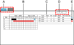
A | Tabs; selects the receive map or the transmit map | B | The map shown in a graphical presentation of how items are placed |
C | The map shown in a table presentation of how items are placed | D | Command buttons to Add or to Delete items from the map |
E | Colour coded example of item positions |
If a row is selected in the list, the item is highlighted in the list and on the map.
If an item is selected on the map it is highlighted on the map and in the list.
An item can occupy one single bit or extend over several bits. An item position is always described with a starting position of the least significant bit. The starting position points to a byte and bit. The length parameter indicates how long the item stretches from right to left.
Items are added or edited in a pop-up window.
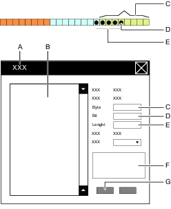
A | Add item or Edit item pop-up window map | B | List of available items |
C | Byte position | D | Bit position |
E | Item length parameter field | F | Item information field |
G | Command buttons |
Automatic Placement of Fieldbus Maps in the Process Data Frame
A Fieldbus map is placed automatically in the Process Data Frame when it is assigned to a virtual station. It is possible to change the order later by editing the Offset position in the Fieldbus virtual station mapping configuraiton menu in the Fieldbus and SoftPLC
tab.
The following methods are used:
A Fieldbus map is placed in the order in which they are assigned to in the Process Data Frame.
Each map starts with an Offset value from the beginning of the frame.
A map is placed at the lowest possible location, just above the previous map or with offset zero for the first map.
If a map is deleted from the Process Data Frame, a gap will be created. When a new map is assigned to a virtual station, the placement rule will try to fill the gap.
If the map cannot fit in between existing maps, then the next free position in the array is tried.
The offset value may be changed manually in the Settings window. Care must be taken that Fieldbus maps do not overlap.
If ToolsTalk 2 detects any violation to the placement rules, an error indicator will appear beside the offset parameter. This indicates that maps overlap or that the map is outside the boundary. This may be corrected by changing the offset value.
A | Starting position of first Fieldbus map in the Process Data Frame; Offset = zero |
B | Starting position of a Fieldbus map in the Process Data Frame; Expressed as an offset from the beginning of the PDF |
C | Size of a Fieldbus map |
D | Fieldbus map |
E | Size of the Process Data Frame |
F | Error example; Blue map overlaps starting position of “green” map |
G | Map size |
H | Starting position of “blue” map |
J | Process Data Frame |
K | First map in the Process Data Frame; Offset address is zero |
Automatic Placement of Items in the Fieldbus Map
Items are placed automatically in the Fieldbus map. It is possible to change the order later by editing the Fieldbus window.
The following methods are used:
Items are placed in the order in which they are added to in the Fieldbus map, within the Fieldbus virtual station mapping configuration menu in Fieldbus and SoftPLC
.An item is placed at the lowest possible location with regards to byte, bit and length position.
If the item cannot fit in between existing items, the next free position in the array is tried.
If an item is deleted from the Fieldbus map, a gap will be created. When a new item is added, the placement algorithm will try to fill the gap.
If ToolsTalk 2 detects any violation of the placement rules. An error indicator
will appear and indicate the error location. By placing the mouse cursor over the error indicator, more information about the rule violation is displayed.
Editing or Viewing an Item in the Fieldbus Map
Select a controller in the Plant structure window
.Select the Fieldbus and SoftPLC
tab in the menu bar.Select the Fieldbus sub-tab to show a list of maps.
Double-click on the name of the selected map.
The workspace shows the configuration menus.
Select either the To Controller tab, or the From Controller tab in Fieldbus configuration menu.
Double-click the item name in the map table in the Fieldbus configuration menu.
The Edit item dialog window opens.
Edit the item starting position by typing the BYTE number in which the least significant BIT is located.
Edit the item starting position by typing the BIT in which the least significant BIT is located.
Edit the Length of the item, expressed in number of bits.
Edit an optional Converter value from the drop-down menu.
Select OK to confirm any changes and to close the dialog window.
The Fieldbus configuration menu is updated in both the map and in the table.
Deleting Items From the Fieldbus Map
Select a controller in the Plant structure window
.Select the Fieldbus and SoftPLC
tab in the menu bar.Select the Fieldbus sub-tab to show a list of maps.
Double-click on the name of the selected map.
The workspace shows the configuration menus.
Select the To Controller tab or the From Controller tab in Fieldbus configuration menu.
For each item to be deleted from the map, select the check box
in the leftmost position in the table of items in the Fieldbus configuration menu.Select Delete .
The Fieldbus configuration menu is updated in both the map and in the table.
Exporting a Fieldbus Map
The Fieldbus map defines how signal items are placed into the communication frame that is used between a virtual station and a remote location. This map can be exported as a template and be imported and reused by another controller.
Select a controller in the Plant structure window
.Select the Fieldbus and SoftPLC
tab in the menu bar.Select the Fieldbus sub-tab to show the workspace and a list of maps.
In the leftmost column in the fieldbus workspace, select the check box
for the fieldbus map to be exported, and then select Manage followed by Export from the drop-down list.Browse to the desired location and select Save.
The map will be saved as a JSON file (*.json). The exported file can be imported to a different controller.
Working with Acyclic Fieldbus Configuration
Some of the data in a tightening result will be sent as acyclic data. The IO signal cycle_complete, usually indicates that the acyclic data is ready to be fetched by the PLC programmer.
The section below explains how to configure the acyclic data.
Acyclic Data Configuration Overview
In the acyclic data configuration area, it is possible to add a new acyclic data configuration and once added, the different acyclic data configurations are displayed as a list.
Select a controller in the Plant structure
. Select the Fieldbus and SoftPLC tab.
.Select the Acyclic sub-tab.
The columns contain the following information:
Column | Description |
|---|---|
Name | Name of the selectable configuration in virtual station mapping. |
|
Select channel by | Bolt or Channel. This value defines if the Identifier of each result configuration item is bolt or channel.. |
Data layout | Compact or Fixed. |
Last changed | Expressed in ToolsTalk 2 time. |
Last changed by | Configuration data last changed by <user>. |
Controller updated | Expressed in controller time. |
Controller updated by | Controller updated by <user>. |
Adding a New Acyclic Data Configuration
Select a controller in the Plant structure
. Go to Fieldbus and SoftPLC tab
.Select the Acyclic sub-tab.
Select Add and select New in the Create new acyclic data configuration window.
Enter the acyclic data configuration name and select Add.
The Properties sub-tab for the newly created configuration opens.
A new acyclic data configuration is added in the lowest possible position and the list is updated.
Acyclic Data Configuration Menu
Double-click on an acyclic data configuration in the Acyclic tab to open the acyclic data configuration menu.
Properties menu:
Parameter name | Description |
|---|---|
Name | Name of the selectable configuration in virtual station mapping. |
Max size | This value will be manually set until it is mapped to a virtual station. This value makes sure that the configuration fits within the selected instances in mapping. The value is calculated from the required number of instances, according data record size. |
First channel or bolt offset | Address of the first channel or bolt offset. This defines the size of the common area. |
Bolt or channel template size | Size of the bolt or channel. |
Select channel by | Bolt or Channel. This value defines if the Identifier of each result configuration item is bolt or channel. |
Data layout | Select between:
|
Add header | Select the check box to indicate that a header must to be added to the acyclic configuration result. When the checkbox is marked, the offset will be updated with 6 bytes lower or higher, depending on the usage. This is also visible graphically. The header can only be added if there is space available. If items are added in the common area and there is no space for the header, it is disabled. If the Compact data layout is chosen, it is strongly recommended to use the header in order to know the length of the acyclic data payload. |
Non existing values | Non existing values for different data types are used if the configuration wants data that is not present in the tightening result or in the multistage configuration. When a new acyclic fieldbus is created, the values will be set automatically from the controller. |
Configure Acyclic Data
The Configure Acyclic Data area displays the visualization of the acyclic configuration set by max size, offset and template size. All configurations are in the byte level.
The acyclic data frame displayed on the left changes when items are added to the common, bolt or channel area.
If the values of offset and template size are zero, the common, bolt or channel area is greyed out and non-editable.
Data in the Common Area
The common area contains data that is global and is applicable to all the spindles in the same station. The common area data is displayed after the header and before the bolt/channel data.
Bolt or Channel Data
The data in the bolt or channel area is unique for the selected bolt or channel and the layout for the data in the bolt or channel area depends on the data layout chosen.
Common Area Overview
The first occupied area contains the following items:
Multiple tightening result
Batch sequence result
Result notification
These items are "common" and are not specific to a bolt or a channel and contain the following parameters:
Parameter name | Description |
|---|---|
Type | Value type of each item. Example: batch sequence result value, result notification or multiple tightening result value. |
Offset | Item position in the byte array with acyclic data frames and is defined in bytes. |
Size | Size in bytes. It is possible to configure this manually if the datatype is a string. If the datatype is not a string, the values are set automatically based on the data type. |
Data type | Data type values. Example: String, Int8, Int16 and so on. |
Name | Item name. Non editable. |
Adding Acyclic Result Configuration in Common Area
Select Add in the Common area.
The Create acyclic result configuration window opens.
Select a parameter from the Multiple tightening, Result notification or Batch sequence drop-down menu.
Select the Output Data Type, enter the offset value and enter the size if the Output Data Type selected was a string.
Select Add and then select Close.
Deleting Acyclic Result Configuration from Common Area
Select the check box for the configuration that needs to be deleted in the Common area.
Select Delete.
Bolt or Channel Area Overview
In the bolt or channel configuration area, it is possible to configure the acyclic data items of the following types for a bolt or a channel:
MultiStage tightening
Program monitor
Program restriction
Step monitor
Step restriction
Parameter name | Description |
|---|---|
Type | Value type of each item. Example: MultiStage tightening, Program monitor, Program restriction, Step monitor or Step restriction. |
Offset | Item position in the acyclic data frame and is defined in bytes. |
Size | Size in bytes. It is possible to configure this manually if the datatype is a string. If the datatype is not a string, the values are set automatically based on the data type. |
Data type | Data type values. Example: String, Int8, Int16 and so on. |
Name | Item name. Non editable. |
Identifier | Sets the ID of the bolt or channel selected. |
Adding Acyclic Result Configuration in the Bolt or Channel Area
Select Add in the bolt or channel area.
The Create acyclic result configuration window opens.
Select a parameter from the Multistep tightening, Program monitor, Program restriction, Step monitor or Step restriction drop-down menu .
Select the Output Data Type, enter the offset value, identifier and enter the size if the Output Data Type selected was a string.
For Step monitor and Step restriction, select the step category and choose between Soft start, Rundown, Start and Final.
Instead of the step number, indicate which step category results should be displayed.
If there are several steps with the same step category, you can choose to show the step that is Last executed or Last in program (the step with higher order number) in the Step category chooser drop-down menu.
Select Add and then Close.
Creating Copies in the Bolt or Channel Area
It is possible to add many bolts or channels at once using the Create copy tab in the bolt or channel area.
Select the check box of the ID that needs to be copied and select Create copy.
The Create copy of bolts or channels window opens.
Enter the number of copies in the Amount of copies field.
If there is no space for a copy, then a warning "The amount of copies cannot fit into the remaining space in the current configuration" is displayed.
Select Create copy and then select Close.
A list of copies with sequential identifier numbers is now visible. The value of the copied ID is always the number after the largest number already existing. For example, if there are ID's 2, 5 and 6 already existing and ID with value 2 is copied, the value of the new ID will be 7. Double-click on the parameters to change any values.
Deleting Acyclic Result Configuration from Bolt or Channel Area
Select the check box for the ID to delete all the configurations under that ID, or to delete an individual configuration, select the check box next to that configuration in the bolt or channel area.
Select Delete.
Example of a Tightening Result
In this fieldbus map, the tightening result data starts at record number 2048 and each record is 64 bytes. The maximum size of the tightening data, including the header is 646 bytes in order to fit up to 64 channels.
Data | Data Type | Position in Frame | Byte | |
|---|---|---|---|---|
a The length of the data part and the sequence and length from the header, that is the length of data plus 4 bytes | ||||
Status | Integer | Header | 0-1 | |
Sequence | Integer | Header | 2-3 | |
Data lengtha | Integer | Header | 4-5 | |
Bolt number channel 1 | Integer | Data | 6-7 | |
Final torque channel 1 | Real | Data | 8-11 | |
Final angle channel 1 | Real | Data | 12-15 | |
Bolt number channel 2 | Integer | Data | 16-17 | |
Final torque channel 2 | Real | Data | 18-21 | |
Final angle channel 2 ....................................... | Real | Data | 22-25 | |
Bolt number channel 64 | Integer | Data | 636-637 | |
Final torque channel 64 | Real | Data | 638-641 | |
Final angle channel 64 | Real | Data | 642-654 | |
The Functionality of the Header Fields
Signal | Data Type | Description |
|---|---|---|
Status | Integer | Added for future use, at the moment always 0x8100 |
Sequence | Integer | Will always be -1 |
Data Length | Integer | The length of the data and the Sequence and Length from the header, i.e. length of data + 4 bytes |
The Functionality of the Data Fields
Signal | Data Type | Description |
|---|---|---|
Bolt Number Channel X | Integer | Bolt number of the channel according to the configuration in the sync mode used in the tightening. For channels that was not included in the tightening the bolt number will be set to 0 |
Final Torque Channel X | Real | Final Torque value from the tightening result for the channel. The value is always sent in the unit Nm. For a channel that was not included in the tightening or that did not produced a Final Torque value it will be set to 0x7F820000 |
Final Angle Channel X | Real | Final Angle value from the tightening result for the channel. The value is always sent in the unit deg. For a channel that was not included in the tightening or that did not produced a Final Torque value it will be set to 0x7F820000 |
The Final Torque and Final Angle values will be sent a floating point binary32 according to ISO/IEC/IEEE60559:2011. Data is transmitted in network order (Big-endian). If a value cannot be sent the special value 0x7F820000 will be sent. If interpreted as a floating point number, it corresponds to NaN (Not a Number).
The integer values are sent as signed 16 bit integers, i.e. the valid range are -32768 to 32767
For example, if a tightening was made with channel 1 and channel 3 and the following tightening data was produced:
Channel 1
Bolt number 1
Final Torque 10.23 Nm
Final Angle 341.4°
Channel 3
Bolt number 5
Final Torque 10.32 Nm
No final angle was produced
The tightening data is sent at instance number 2048 as following:
Byte | Field | Value | Comment |
|---|---|---|---|
0-1 | Status | 0X8100 | Will always be 0X8100 |
2-3 | Sequence | -1 | Will always be -1 |
4-5 | Length | 34 | 34 bytes, data for three channels + length and sequence number |
6-7 | Bolt Number Channel 1 | 1 | |
8 - 11 | Final Torque Channel 1 | 10.23 | 10.23 Nm |
12-15 | Final Angle Channel 1 | 341.4 | 341.4° |
16-17 | Bolt Number Channel 2 | 0 | Not included in the tightening |
18-21 | Final Torque Channel 2 | 0x7F820000 | No torque value available |
22-25 | Final Angle Channel 2 | 0x7F820000 | No angle value available |
26-27 | Bolt Number Channel 3 | 5 | |
28-31 | Final Torque Channel 3 | 10.32 | 10.32Nm |
32-35 | Final Angle Channel 3 | 0x7F820000 | No angle value available |
SoftPLC Configuration Tab
SoftPLC Overview
The SoftPLC is used to customize the behavior of PF6/PFFlex, sending and receiving fieldbus data, or exchanging I/O signals to and from the external SoftPLC. The external SoftPLC is used for control of machinery on assembly lines. Configuration and programming is done through a third party software called MultiProg, integrated with ToolsTalk 2, though running in a process of its own. The SoftPLC is found in the Fieldbus and SoftPLC tab and is visible for controllers supporting this function either by license and/or capability.
Controller features, such as the Low Reaction Tightening Strategies and controller-wide functions among others, require licenses distributed through the Functionality Management System (FMS). Whereas configuration of features is possible without specific licenses, the assignment and use of those features will require the correct license to be installed on the controller. Please refer to Licenses (FMS) for more detailed information on licenses.
Creating SoftPLC Signal Configurations
Interaction between accessories and the SoftPLC is done through exchanging I/O signals.
Select Add in the SoftPLC Signal Configurations field to see the list with all supported I/O signals connected to this controller.
Clear the irrelevant signals in order to exclude them from the SoftPLC signal configuration (all signals are selected by default).
Name the signal configuration list.
The created signal configuration is then available as an option to select from the drop-down list when mapping the signal configurations to the virtual station.
The signals that are not included in a signal configuration (not checked), will still be visible in the SoftPLC configurator Multiprog, but crossed out.
SoftPLC Virtual Station Mapping Configuration
Creating a New SoftPLC Mapping
Select Add in SoftPLC Virtual Station Mapping Configuration
In the Create a New SoftPLC Mapping window, select the required Virtual station and the SoftPLC Signal Configuration from the drop-down menus.
The same SoftPLC signal configuration can be used for multiple virtual stations.
Each virtual station can use one SoftPLC signal configuration. When a virtual station is mapped with a particular signal configuration, it is no longer available in the drop-down menu when creating a new SoftPLC mapping. To make it available, delete the existing mapping for that virtual station.
SoftPLC Index: Connect specific virtual stations on the controller to an ordered index in the SoftPLC environment. For example, if the SoftPLC refers to virtual station 2, this mapping will inform the SoftPLC exactly which virtual station currently is number 2.
Select Update in the Project Virtual Stations to see any changes you made to a SoftPLC Signal Configuration or SoftPLC Mapping in the SoftPLC project. ToolsTalk 2 will not delete variables in the Multiprog SoftPLC project when updating, and it can only add or modify. Because of this, it is recommended to clear the global variables for Virtual stations or Fieldbus in Multiprog before updating.
Deleting a SoftPLC Mapping
Select the virtual station signal configuration mapping by marking the corresponding check box. Select Delete.
Creating a New SoftPLC Project
Create a new SoftPLC Signal Configuration.
Assign the SoftPLC Signal Configuration to the virtual station.
Select SoftPLC ON in General SoftPLC Settings.
Select Create New and the Multiprog opens automatically to a new SoftPLC project.
This project will use the basic template and this template includes all functions available in Multiprog.
The created and edited project is continuously saved to the local disc when the project is built and stored in Documents > Mp Temp. At the ToolsTalk 2 SoftPLC startup, when OPEN is selected, the stored data project is uploaded and used if the SoftPLC project has not been saved to the ToolsTalk 2 server.
Edit the SoftPLC program in Multiprog and give the project a Name and Description in ToolsTalk 2.
Add virtual station mappings with I/O signal configurations by selecting Update in the Project Virtual Stations field.
Add Fieldbus data by selecting Update in the SoftPLC framesize in fieldbus field.
The fieldbus frame size must be configured to contain a special SoftPLC input/output part to be able to send and receive fieldbus data directly to/from the SoftPLC.
Select Save to check in the edited project to the ToolsTalk 2 server.
Push the changes to the controller.
Deleting a SoftPLC Project
Deleting a project
Select Delete in the Project area. Select Delete again in the dialog window to confirm.
Creating SoftPLC User Data
The integration is implemented so that we have shared memory mapped between the SoftPLC and the OpenProtocol adapter and upto six virtual stations are supported. A virtual station is allotted 100 bytes for the data to the SoftPLC and 100 bytes for the data from the SoftPLC. A total of 600 bytes is mapped in both directions in total.
The SoftPLC can interact with protocol adapters through a dedicated part of the shared memory.
Select Add in the General SoftPLC Settings field.
In the Create SoftPLC user data window, choose the relevant protocol from the drop-down.
Fill in the To SoftPLC and From SoftPLC address fields with 0 for the Start addresses and 599 for the End addresses.
Select Add.
The Global_Variables* section in the Multiprog software will contain the output variables (opOUT_VSX) and input variables (opIN_VSX) for each virtual station with the following addresses.
Virtual Stations
Open Protocol user Data To SoftPLC
Open Protocol user Data From SoftPLC
Virtual Station 1
%MB3.38400
%MB3.40448
Virtual Station 2
%MB3.38500
%MB3.40548
Virtual Station 3
%MB3.38600
%MB3.40648
Virtual Station 4
%MB3.38700
%MB3.40748
Virtual Station 5
%MB3.38800
%MB3.40848
Virtual Station 6
%MB3.38900
%MB3.40948
If you are importing or updating a project that does not already have the above addresses set, then it must be manually added in Multiprog.
Select SoftPLC ON or OFF.
On: If the SoftPLC process is lost the tool will be locked from performing any tightenings.
Off: If the SoftPLC process is lost the tool will still be able to perform tightenings.
Perform open protocol operations in the controller.
Push the changes to the controller.
Setting Up SoftPLC Communications
In the open Protocol Client, subscribe user data with MID0241.
Controller accepts the command by sending MID0005 to the Open protocol client.
The Open protocol client uses MID0240 to download user data from the controller.
Controller accepts the command by sending MID0005 to the Open protocol client.
Controller uses MID0242 to send data out to the Open Protocol client.
Open protocol client acknowledges with MID0243 that it has received user data.
Refer to the document "OpenProtocol Appendix for PowerFocus 6000 SW1.5.docx " for further information.
Importing a SoftPLC Project Template
New SoftPLC projects can be created from an existing project template. The templates will serve as a basic suggestion which can be further adjusted. The selected project template is then copied, as to not overwrite the original project.
Select Import Project and select an existing SoftPLC project.
Edit SoftPLC project in the Multiprog.
Add virtual station mappings with I/O signal configurations by selecting Update in Project Virtual stations.
Add Fieldbus data by selecting Update in SoftPLC framesize in fieldbus.
Select Save to check in the edited project to the ToolsTalk 2 server.
Push the changes to the controller.
Select Update in Project Virtual Stations and the SoftPLC virtual station mappings are added or updated to the SoftPLC project, if not already included in the project.
Working with the System Administration Tab
The System administration tab in ToolsTalk 2 is located in the left side menu bar and provides the following functionality:
System administration Tabs | Description |
|---|---|
| Controller Software and Data Management Manages software updates to all controllers. Organize controllers into Custom sections. |
| Scheduled Task Controller configurations can be exported and imported at scheduled intervals. |
| Compare Configuration Side by side comparison of two exported files. |
| Functionality Management System (FMS) Manages the distribution of licensed functionality among the connected controllers. |
| User Groups Different permissions to see or edit information in ToolsTalk 2 can be given to various user groups. |
Controller Software and Data Management
Export controller results and settings.
Import controller settings.
Load new controller software.
Switch between controller software installations.
Generate report.
Organize controllers in Custom sections.
Export controller configuration parameters and leave the controller program unchanged.
Import a new controller configuration.
Software update changes the controller's software. Controller name, IP address, and server connections can be manually entered.
Scheduled Tasks
Export controller results and settings.
Import controller settings.
Scheduling of export and import task to selected controllers.
Database maintenance
Push controller configuration
Export/import changes a controller's configuration parameters and leaves the controller's program unchanged. Controller names, IP addresses and server connections are unaffected by these operations.
Functionality Management System
Add licensed functionality to a controller.
Remove licensed functionality from a controller.
Manage a pool of licensed functionality.
Load additional functionality from Atlas Copco when needed and return functionality when not needed any more.
User Groups
Create different user groups.
Manage the rights to view folders and individual controllers.
Manage the rights to configure ToolsTalk 2 functionality.
Manage the rights to configure controller parameters and functionality.
Controller Software and Data Management
Introduction to Controller Software and Data Management
Go to System administration , and then select Controller Software and Data Management
.
Export controller results, configurations and settings.
Import controller settings.
Load new controller software.
Switch between controller software installations.
Generate report.
Organize controllers in Custom sections.
Search for controllers.
Export/import: Changes the controller's configuration parameters and leaves the controller's software program unchanged.
Software update: Changes a controller's software and leaves the controller's configuration parameters unchanged.
Controller names, IP addresses and server connections are unaffected by these operations.
Column | Description |
|---|---|
Controller | Controller name. |
Controller Type | Which controller type that applies. |
Factory port | On: For controllers with enabled communication via factory port. No text is displayed if the connection is disabled (set to off in the controller settings). |
Current version | Current software version. Red: Software is not in the approved software list. Add it to the list by clicking the Add command button and enter the current software version. Black: Software is in the approved software list. |
Stored version | Stored inactive software version. |
Operation | Shows any ongoing operation such as: Task status and result during import and export, and software update task status and result. |
Select the box to the left of the controller name to activate the options listed in the table below.
Button | Description |
|---|---|
Restart | To restart the selected controller |
Generate Report | Generates the SoftwareVersionReportcsv.csv file and opens a dialog pop-up window for storage selection. |
Software |
|
Export/Import |
|
Button | Description |
|---|---|
Edit | Activate and deactivate the Edit mode for organizing Custom sections. |
+ | Adds a Custom sections folder or subfolder. Only visible in Edit mode. |
- | Deletes a Custom sections folder or subfolder. Only visible in Edit mode. |
The export and import function also exists in Controller Configurations and in the Scheduled Export and Import . The file format and the results are the same.
The right-side of the workspace window contains a list of approved software which is authorised to execute in a controller. Non-approved software is marked in red in the Current Version column.
Command | Description |
|---|---|
Add | Opens a shortcut menu to enter a new software version to the list. |
Delete | Removes one or more selected software versions from the list. |
The Generate report creates a SoftwareVersionReportcsv.csv file containing a matrix with the following information in the columns:
Controller name.
Current software version.
Stored software version.
Indication if the current software is approved or not.
To organize the controllers in the Plant structure and to access the shortcut options below, click on the controller name. The background color of the controller name will change to light blue.
A maximum of 20 controllers can be selected at any one time.
Right-click on a controller to get the below options.
Shortcut menu | Description |
|---|---|
Add new controller | Add a new controller to the Plant structure controller list. |
Connect controller | Set controller status to online. |
Disconnect controller | Set controller status to offline. The controller name will be struck through |
Reset operation status | Force controller status to reset. Clears the current status and resets to idle. This does not interrupt the started process and acts as a failsafe if the connection is lost. |
Delete | Deletes a controller from the Plant structure controller list. If a controller is deleted from the All controllers folder it will be permanently deleted. |
Searching for Controllers
In the Controller Software and Data Management workspace, there are two search fields. One field only searches for controllers in Custom sections and the other one searches for all controllers in the controller list.
In the search field, enter at least two letters of the controller name.
It is possible to search for either the controller name, or Type. In the main controller list, it is also possible to search for Software version (Current version).
Exporting and Importing Controller Configurations and Tool Logs
The export/import function is used to export the events and tightening results accessible in the Results menu for analysis in external programs, as well as allowing transfer of tightening program, batch, and controller configurations between controllers.
The command Export/Import can be used for the following reasons:
Exporting tightening results and events for further processing.
Exporting log files for debug assistance from an Atlas Copco service engineer.
Exporting the entire controller configuration that can be used to copy the configuration to another controller.
Comparing two exported configurations to see differences.
Importing controller configurations.
Exporting
Select theSystem administration tab
 .
.Go to Controller software and data management
 .
.Select the check box
of the controller. It is only possible to export a controller configuration if the controller is online.Select Export/Import to export one of the following:
Parameter
Description
Export
Exports all controller information.
The exported file will have a file name and extension that looks like <Filename>.tar.gz.
Export Configuration
Exports settings and configurations.
The exported file will have a file name and extension that looks like <Filename>.tar.gz.
Export Tool Log
Exports logs (tightenings and hardware information) from connected tools. Available for SRB, TBP and STB.
The export consists of atlas_tool_i.zip and ExportInfo.txt
Select the location for saving the export file, select OK.
The filename consists of one part to identify the controller and of one part which is a time stamp.
Importing a controller configuration
The purpose of the Import command is to copy a controller setting and to reuse a previously exported source file and shall have a file name and extension that looks like <Filename>.tar.gz.
Select System administration
in the left-side menu bar.Select Controller software and data management
in the upper menu bar in the workspace window.Select the check box
of the controller. It is only possible to import to a controller configuration if the controller is online.Select Export/Import.
The Import to selected dialog window opens.
Select Open file and browse to the selected file.
Select the file and select Open.
The file path is shown and the Import button is active. Select Import.
After restarting, the imported file is now in use with a new configuration setting.
A file import does not change the program of the controller. It changes every setting and configuration except the factory IP address.
Updating Controller Software
Updating and switching controller software are two different tasks that are tightly connected. The controller can have two different software versions installed, one active version and one passive version. It is a simple process to switch between the two versions. Switching controller software is the task that switches active and passive software.
Loading New Software to the Controller:
Select the System administration tab
.Go to Controller software and data management
.Select the check box
of the controller. It is only possible to update the controller software if the controller is online.Select Software then Software update from the drop-down menu.
The Software update dialog window opens.
Select Open file and browse the selected file.
The file name should end with -px2it.zip
Mark the file and select Open.
The file path is shown and the button Software update is active. Select the button to start loading the software.
Switching Controller Software
Updating and switching controller software are two different tasks that are tightly connected. The controller can have two different software versions installed, one active version and one passive version. It is a simple process to switch between the two versions. Switching controller software is the task that switches active and passive software.
Activating Stored Software in the Controller
Select the System administration tab
in the left-side menu bar.Go to Controller software and data management
 .
.Select the check box
for the controller. It is only possible to execute the command if the controller is online.Select Software then Activate stored Software from the drop-down menu.
The Software update column in the workspace will show the following messages:
Activating stored software.
Stored software activated, controller restarting.
Generating a Controller Software Report
The Controller update workspace shows all the controllers and both their current running software and the stored software.
Generating a List On File:
Select the System administration tab
in the left-side menu bar.Go to Controller software and data management
.Select Generate report.
The browser dialog window opens.
Select a file location and select Save.
The SoftwareVersionResultcsv.csv file will be written to the selected location.
Managing Custom Sections
Go to the System administration tab
, and then select Controller Software and Data Management
.In Custom sections, select Edit
 to enter the Edit mode. Edit will change color to light blue to indicate it has been selected and two new buttons appear, a + and a -,
  .
.
When in Edit mode, the following organizing options are available:
Creating a new folder
Creating a new subfolder
Deleting a folder or subfolder
Copying a controller to a folder
Changing the display order of folders and controllers
To exit the Edit mode:
Select Edit to exit the edit mode. Edit will change color and the + and - buttons will disappear.
Creating a New Folder
To the left of the Edit button, select the + button
or
Right-click anywhere in the folder area and choose Add folder in the shortcut menu.
A New folder will be created and added to the list.
Select the New folder . The color will change to light blue to indicate that it has been selected.
Press F2, re-name the folder and press Enter.
Creating a New Subfolder
To the right of the folder name, click the + button
or
Right-click on an existing folder and select Add folder in the shortcut menu.
A New folder will be created and added to the list.
Select the New folder. The color will change to light blue to indicate that it has been selected.
Press F2, re-name the folder and press Enter.
Deleting a Folder or Subfolder
To the right of the folder name, select the - button
or
Right-click on an existing folder and click Delete in the shortcut menu.
The folder will be deleted and the copies of the controllers will be removed.
When a folder containing subfolders is deleted, all the subfolders are deleted too.
Copying a Controller to a Folder
Select All controllers, or the appropriate Custom section, from the drop-down menu above the controller list.
Select a controller. The color will change to light blue to indicate that it has been selected.
One or many controllers can be selected.
Press Ctrl+ Left click to add one controller at the time to the selection.
Press Shift+ Left click to add multiple controllers at once to the selection.
Drag the selected controllers to the destination folder.
Changing the Order of Folders and Controllers
Drag the selected folder or controller to its new position.
Scheduled Tasks
Go to the System administration tab , and select Scheduled Task
 . The workspace displays the following information.
Column | Description |
|---|---|
Check box | Select a task by using the check box. |
Name | Task type. |
Last changed | Time stamp for latest changes. |
Changed by | Task modified by... |
Latest run | Last time the task was executed. |
Running | Status information of a currently running task. |
Command | Description |
|---|---|
Execute now | One or more tasks can be selected and forced to execute immediately, without waiting for the set scheduled date and time. The Backup location settings must be defined in order for 'Execute now' to work. |
Add | Create a new task. Select task type. |
Delete | Delete one or more tasks from the task table. |
The list of controllers on the right side displays which controllers that are affected by the scheduled task. The list is only populated if one or more tasks are selected.
Administrating Scheduled Tasks
Go to System administration
.Go to Scheduled task
.
Double-click on an existing task to view the configuration.
Menu | Description |
|---|---|
Properties | Issue the task a name and description. |
Schedule | Time and interval settings for the task. |
Controllers | Select which controllers are affected by the task. |
Results | The result of the task. |
Import file | Only visible if the task type is import controller configuration. |
Backup location | Only visible if the task type is export controller configuration. |
Adding a New Scheduled Task
Select Add.
Select a Scheduled task type:
Export controller configurations
Import controller configurations
Database Maintenance
Push controller configuration
Export License Distributions
Execute Now
Select a task by selecting the corresponding check box.
Select Execute now in order to run the task immediately.
Deleting a Scheduled Task
Select a task by selecting the corresponding check box, and then select Delete to remove the selected task.
The deleted task is removed from list of scheduled tasks.
Editing a Scheduled Task
Double-click on the task to be edited.
Edit the scheduled task.
Changes are automatically saved and no Push is needed.
The export and import function also exists in Controller configurations and in the Controller software and data management . The file format and the results are the same in both cases.
Controller Selection
Valid for the Import, Export, and Push controller configuration scheduled tasks.
Select the controllers on which to run the scheduled task.
Parameter | Description |
|---|---|
Schedule all controllers | When set to Yes, the scheduled task will run on all controllers that are connected to ToolsTalk 2 and that are visible in the plant structure The controller list will not be visible when set to Yes. When set to No, the controller list will be visible and individual selections are possible. |
Toggle all | All controllers are automatically marked and the task will run on all controllers. It is possible to deselect individual controllers. |
| Select the controllers on which to run the scheduled task. The task will affect the selected controllers only. |
Important difference between Toggle all and Schedule all controllers:
Toggle all |
|---|
Easy to select or deselect individual controllers. A static list. If new controllers are added, they are not automatically included. |
Schedule all controllers |
|---|
Any changes in the structure with connected controllers will not alter the scheduled task. Dynamic list, all controllers are affected. |
Important notice:
If an import is made to several controllers using the same import file, the controller name field is overwritten by the name of the controller in the imported file. Resulting in all controllers having the same name.
Further import or export with named controllers will fail, as the name will not be recognized anymore.
One way to overcome this issue is to set the Schedule all controllers to Yes.
Export Controller Configuration
This menu is visible if the Scheduled task type is Export controller configuration.
Parameter | Description |
|---|---|
Backup location | Enter a valid path to the location to which the export file is to be written. The default value is empty with an error indicator The path must be valid when the scheduled task is executed. |
File name | The exported file is in the format : *.tar.gz It can later be used to import configurations to controllers or sent to Atlas Copco for debugging purpose or failure analysis. The default filename is something like PFExport_<controller-name>_<Date-code>.tar.gz. System variables can be used to differentiate and to create unique filenames. |
Folder per controller | When set to Yes, each export will be saved in a separate sub folder. When set to No, the exports will be saved in the Save Location folder. |
Folder name | System variables can be used to differentiate and to create unique folder names. |
System variables can be used to specify file names and folder names for the export. They are added at runtime, to the file name or folder to create unique export files or locations.
The system variables are written inside brackets, and the following may be used:
[ControllerName]
[IpAddress]
[ControllerSerialNumber]
It is possible to combine text with system variables. An example is Station_3_[ControllerName]_[IpAddress]. If the controller name is ABC and its IP address is 10.25.25.180, the resulting filename at runtime will be Station_3_ABC_10.25.25.180.tar.gz.
A scheduled file export can only occur if the controller is online at the time of the export and that the export path is valid.
Parameter | Description |
|---|---|
Enabled | When set to Yes, the scheduled task will run according to the scheduled configurations. When set to No, the scheduled task will not run. |
Weekdays | Mark one or more weekdays when the task will run. |
Time | Select a run time from the drop-down menu. |
Start date | Select a start date for the run time from the calender icon. |
Select end date | When set to Yes, the scheduled task will run according to the schedule until the end date. When set to No, the scheduled task will run according to the schedule from the start date. |
After a task is executed, the results are shown in the Results menu.
Parameter | Description |
|---|---|
Status | The scheduled task status after running the task can show OK or NOK. |
Controller | Displayed if available for the task. |
Latest run | Time and date when the scheduled task was executed. |
Error | Error code examples if the status is NOK.
|
Import Controller Configuration
This menu is visible if the Scheduled task type is Import controller configuration.
Menu item | Description |
|---|---|
File name | The file and name must be a previously exported configuration file. It must be in the format : *.tar.gz |
Browse | The command opens the browser window to locate the file to import. |
The file is loaded into ToolsTalk 2 and the scheduled task runs at the scheduled times.
A file import does not change the program of the controller. It changes every setting and configuration except the factory IP address.
A scheduled file import can only occur if the controller is online at the time of the import.
Parameter | Description |
|---|---|
Enabled | When set to Yes, the scheduled task will run according to the scheduled configurations. When set to No, the scheduled task will not run. |
Weekdays | Mark one or more weekdays when the task will run. |
Time | Select a run time from the drop-down menu. |
Start date | Select a start date for the run time from the calender icon. |
Select end date | When set to Yes, the scheduled task will run according to the schedule until the end date. When set to No, the scheduled task will run according to the schedule from the start date. |
After a task is executed, the results are shown in the Results menu.
Parameter | Description |
|---|---|
Status | The scheduled task status after running the task can show OK or NOK. |
Controller | Displayed if available for the task. |
Latest run | Time and date when the scheduled task was executed. |
Error | Error code examples if the status is NOK.
|
Database Maintenance
Events such as controller configurations, libraries, tightening programs, device settings, results, etc. are automatically added to the previously saved events in the database. To clear the database in order to save space, and to make the system more efficient, the history data can be deleted, keeping only the latest results of all the events. Taking "snapshots" of the latest results of all the events can be scheduled in the Database Maintenance feature.
Archive data: Select yes to save (archive) the history data in the database. History data will be deleted after every snapshot if selecting no. Note that the results of the taken snapshots are saved regardless.
Only one instance of Database Maintenance task type can be defined at a time.
Parameter | Description |
|---|---|
Enabled | When set to Yes, the scheduled task will run according to the scheduled configurations. When set to No, the scheduled task will not run. |
Weekdays | Mark one or more weekdays when the task will run. |
Time | Select a run time from the drop-down menu. |
Start date | Select a start date for the run time from the calender icon. |
Select end date | When set to Yes, the scheduled task will run according to the schedule until the end date. When set to No, the scheduled task will run according to the schedule from the start date. |
After a task is executed, the results are shown in the Results menu.
Parameter | Description |
|---|---|
Status | The scheduled task status after running the task can show OK or NOK. |
Controller | Displayed if available for the task. |
Latest run | Time and date when the scheduled task was executed. |
Error | Error code examples if the status is NOK.
|
Push Controller Configuration
This menu is visible if the Scheduled task type is selected to Push controller configuration.
Parameter | Description |
|---|---|
Enabled | When set to Yes, the scheduled task will run according to the scheduled configurations. When set to No, the scheduled task will not run. |
Weekdays | Mark one or more weekdays when the task will run. |
Time | Select a run time from the drop-down menu. |
Start date | Select a start date for the run time from the calender icon. |
Select end date | When set to Yes, the scheduled task will run according to the schedule until the end date. When set to No, the scheduled task will run according to the schedule from the start date. |
After a task is executed, the results are shown in the Results menu.
Parameter | Description |
|---|---|
Status | The scheduled task status after running the task can show OK or NOK. |
Controller | Displayed if available for the task. |
Latest run | Time and date when the scheduled task was executed. |
Error | Error code examples if the status is NOK.
|
Backup License Distributions
This Scheduled Task is used for creating backups of the License Distributions on a regular basis. The backups are stored on the ToolsTalk2 server and in the event of a ToolsTalk 2 license downgrade, the backup can then be used to restore the controllers with the reserved licenses again.
Only one instance of Backup License Distributions task type can be defined at a time.
Setting Up the Backup License Distributions Task.
Properties
Name
Enter a name for the backup.
Description
Enter a description for the backup.
Schedule
Enabled
When set to Yes, the scheduled task will run according to the scheduled configurations.
When set to No, the scheduled task will not run.
Weekdays
Mark one or more weekdays when the task will run.
Time
Select a run time from the drop-down menu.
Start date
Select a start date for the run time from the calender icon.
Select end date
When set to Yes, the scheduled task will run according to the schedule until the end date.
When set to No, the scheduled task will run according to the schedule from the start date.
Backup Location
File name
Enter a file name for the backup.
Results
Status
The scheduled task status after running the task can show OK or NOK.
Latest run
Time and date when the scheduled task was executed.
Error
NoWriteAccessToStorage
ExportFailed
TimedOut
Restoring the License Distributions from a Backup
In the event of a ToolsTalk2 license downgrade, the License Distribution backup can be used to restore the License Distributions to the controllers again. The restore is performed by first downloading the License Distributions Backup, and then importing the downloaded backup.
Downloading a License Distributions Backup
Select the System Administration tab
, and then go to the Scheduled Tasks tab .In the workspace, double-click on the Backup License Distribution task.
In Results, select
 to download the License Distribution backup that is to be restored.
In the Save As dialog , browse to a location for the download, and then select Save.
Importing a License Distributions Backup
The downloaded file will now be accessible for import via the Functionality Management System tab  , using the License Distributions Import function.
Functionality Management System (FMS)
Functionality Management System Introduction
The Functionality Management System (FMS) allows Atlas Copco customers to use additional desired features, when they are needed, through a dynamic licensing scheme.
After receiving a purchase order, the customer’s account in Atlas Copco License Portal (ACLP) will automatically receive the purchased features within 24 hours and these features can be downloaded as a license file.
This capability file (included in the license agreement) is loaded in the Local License Server (LLS) where it is decoded and available for distribution.
A pool of features is created and may be used across a number of controllers. A desired feature item can be uploaded to the controller when needed, and be returned to the pool when it is not needed anymore.
In the Atlas Copco License Portal (ACLP) it is possible to manage an account with all features, entitle and return licenses to/from a license server.
The creation and management of a customer account in the ACLP is not covered in this documentation.
Functionality Management System Definitions
License distribution | Function |
|---|---|
Local License Server (LLS) | A unit that holds the pool of feature items and that can distribute the feature items to the license manager in a controller. |
Atlas Copco license portal (ACLP) | A unit that can send a license file, containing all the desired feature items, to the customer. |
License | Access rights to feature items. The license states the conditions for how the feature items may be used. |
License Manager | A function in the controller that loads, manages and returns feature items. |
Virtual Station Type | A license for a fixed collection of features bundled together. Can be assigned in its entirety to a virtual station. |
Virtual Station Feature | A license for an individual controller feature, e.g. TurboTight or TrueAngle. |
Controller Feature | A license for a controller-wide feature, e.g. Step Sync or Soft PLC. These are assigned per controller and are not restricted to any virtual station on that controller. |
Feature item | A piece of software code that can be loaded into the controller to provide additional functionality. The usage conditions are covered by the license agreement. |
Intelligent Application module (IAM) | A storage module that contain all the controller programs, configurations and results. Certain modules may also include additional loaded feature items. |
Reservation list | The distribution server has a pool of feature items. Some of them are allocated to controllers and some are free for distribution. The reservation list contains information on how feature items are allocated. |
Borrow time | Applicable in a networked distribution environment. A controller must periodically check with the LLS and synchronize its feature items with the reservation list. |
Expired license | Changes may be made in the controller configuration or program, and a mismatch between the loaded feature items and the content of the reservation list may occur. In this case an error event will be displayed if a feature item is used that has expired on the controller. |
Capability file | The binary file that is downloaded from the ACLP. It contains all the valid feature items. When it is decoded and stored on the server, a pool of feature items is available for distribution to the controllers. |
Editing the Distribution of License Types and Features
The available License Types and Features can be either added, or removed from the controllers.
Select the System Administration tab
.Select the Functionality Management System tab
to display an overview of the License Distribution on the controllers.Select the Edit
 button for a specific controller. A dialog window with the available license types and features opens.
Select each of the tabs to enter the count for each license type, or feature, that shall be available on the controller.
Select OK to save and continue.
Managing License Distributions
The ToolsTalk2 server automatically stores an internal backup of the last successful License Distributions state. This backup can be exported from the system.
In the event of a ToolsTalk2 license downgrade, where the hosted Flexera license service database has been reset (deleted), a new license file will have to be generated from the Atlas Copco Customer License Portal (ACLP) and uploaded into ToolsTalk2 via the Functionality Management System tab . With the database reset, the License Distributions are also reset and will have to be restored. Use the Export/Import License Distributions to perform the restore.
Select the System Administration tab
, and then the Functionality Management System tab .Select the MANAGE button, and then select License Distributions... from the list.
Select the Export tab.
Specify a location for the export, and then select Export.
Importing License Distributions requires that the license file has first been uploaded, so that the system knows how many licenses are available to distribute.
Select the System Administration tab
, and then the Functionality Management System tab .Select the MANAGE button, and then select License Distributions... from the list.
Select the Import tab.
Browse to the import file location, and then select Import.
 WARNING! This action will remove any existing reservations and restore the License Distributions to the state in the imported file.
Distribution of Feature Items
In the Functionality Management System (FMS) workspace, a user can manage licenses on all the controllers that are connected to the Local License Server (LLS) and online to the ToolsTalk 2 server.
Select the System Administration tab
.Select the Functionality Management System tab
to display an overview of the License Distribution on the controllers.
The view and information below assumes that a capability file has been received from Atlas Copco, and that it is loaded into the LLS.
License Distribution Overview
The License Distribution Overview is made up of several Sub-Tabs, these are explained below.
Controller
The Controller sub-tab displays the pool of Licensed Feature Items, that are distributed across controllers. For a more detailed overview, select a specific row to expanded it and view the controller's current capabilities
Column | Functionality |
|---|---|
Edit | For editing the number of licences distributed on the controllers. |
Controller | Name issued to the controller. |
Virtual Station Types | The amount of licences, by type, distributed to each controller. |
Virtual Station Features | Features that are present on each Virtual Station. |
Controller Features | Features that are present on each controller. |
Virtual Station Types
The Virtual Station Types sub-tab displays the pool of Licensed Virtual Station Feature Types, that are distributed across controllers.
Column | Functionality |
|---|---|
Virtual Station Types | Type of License. |
Controller Name | Name issued to the controller. |
Count | The amount of Licensed Feature Types distributed to the controllers. |
Available | The amount of Licensed Feature Types available to distribute to the controllers. |
On controller | The amount of controllers on which the Licensed Feature Types are active. |
Reserved | The amount of controllers on which the Licensed Feature Types are reserved. When a license is assigned to a controller from ToolsTalk 2, that license is reserved for that controller in the License server. When the controller connects and syncs with the license server, the license will be in both the states Reserved and On controller. |
Total | The amount of Licensed Feature Types available in total. |
Virtual Station Features
The Virtual Station Features sub-tab displays the pool of Licensed Virtual Station Feature Items, that are distributed across controllers.
Column | Functionality |
|---|---|
Virtual Station Features | Type of Feature |
Controller Name | Name issued to the controller. |
Count | The amount of Licensed Feature Items distributed to the controllers. |
Available | The amount of Licensed Feature Items available to distribute to the controllers. |
On controller | The amount of controllers on which the Licensed Feature Items are active. |
Reserved | The amount of controllers on which the Licensed Feature Types are reserved. When a license is assigned to a controller from ToolsTalk 2, that license is reserved for that controller in the License server. When the controller connects and syncs with the license server, the license will be in both the states Reserved and On controller. |
Total | The amount of Licensed Feature Items available in total. |
Controller Features
The Controller Features sub-tab displays the pool of Licensed Controller Feature Items, that are distributed across controllers, these are dictated by the Tool License
Column | Functionality |
|---|---|
Controller Features | Type of Feature |
Controller Name | Name issued to the controller. |
Count | The amount of Licensed Feature Items distributed to the controllers. |
Available | The amount of Licensed Feature Items available to distribute to the controllers. |
On controller | The amount of controllers on which the Licensed Feature Items are active. |
Reserved | The amount of controllers on which the Licensed Feature Types are reserved. When a license is assigned to a controller from ToolsTalk 2, that license is reserved for that controller in the License server. When the controller connects and syncs with the license server, the license will be in both the states Reserved and On controller. |
Total | The amount of Licensed Feature Items available in total. |
FMS Portable
The FMS Portable sub-tab displays the amount of FMS Portable Devices, that are distributed across controllers.
Column | Functionality |
|---|---|
FMS Portable | ID number of the FMS Portable device. |
Controller Name | Name issued to the controller. |
FMS Workspace Features
Command Button
Command button | Functionality |
|---|---|
Manage |
|
The Capability file is a binary file that contains the license items. The file is created in the Atlas Copco Licensing Portal (ACLP) and downloaded to the customer. When decoded in the distribution server, a pool of features is created that can be distributed to the controllers in two ways:
A networked distribution system using the Functionality Management System server which is controlled through the ToolsTalk 2 user interface.
A manual distribution system using a secure USB flash drive that is inserted into each controller and managed through the controller user interface. It is described in detail in the controller documentation.
General Information
Column | Functionality |
|---|---|
Host Id | A unique identity of the distribution server on which the capability file is loaded. |
ToolsTalk2 License | The name of the current functionality level. |
ToolsTalk2 Virtual Stations | Number of configured virtual stations / total virtual stations available for configuration |
Editing the Distribution of License Types and Features
The available License Types and Features can be either added, or removed from the controllers.
Select the System Administration tab
.Select the Functionality Management System tab
to display an overview of the License Distribution on the controllers.Select the Edit
button for a specific controller. A dialog window with the available license types and features opens.Select each of the tabs to enter the count for each license type, or feature, that shall be available on the controller.
Select OK to save and continue.
User Groups
User Groups Overview
This feature is only visible for users that have user rights as Administrator in ToolsTalk 2.
The User group function in ToolsTalk 2 provides the following functions:
Creating or deleting user groups.
Assigning user access rights to folders and controllers.
Assigning user rights to change controller configurations and parameter settings.
Assigning user rights to distribute library functions to several controllers and ToolsTalk 2 administrative tasks.
Viewing the user groups:
Select System administration
in the left menu bar.Select User group
 in the top menu bar.
Each row in the workspace table represents one user group that can be given different user rights.
The columns have the following headers from left to right:
Column | Description |
|---|---|
Check box | To select or deselect a user group. |
Name | User group name. |
Description | Optional field. |
AD group | Active Directory group name. Created by the IT department. |
| Not an actual column. The list of configurations can be sorted in rising or falling alphabetical order, numerical order or time order. Click on the table header row to make an arrow visible and click on the arrow to change the current sorting direction. One arrow is shown at a time. |
The top row in the table is named Administrators. This user group cannot be deleted.
Command | Description |
|---|---|
Add | Create a new user group. A dialog window opens. |
Delete | Delete one or more user groups from the group table. |
User Group Prerequisites
It is possible to create several user groups in ToolsTalk 2. Each of the user groups can be given different user rights to create, read, update and delete parameters, configurations and folders in ToolsTalk 2.
A network administrator in the company IT department must create one or more Active Directory (AD) groups. An AD group can be assigned to one user group in ToolsTalk 2. Each user group in ToolsTalk 2 can be given one unique set of user rights.
Thus, for every combination of ToolsTalk 2 user rights one AD group must be created. Individual users are assigned to one or more AD groups. All members in the user group have the same user rights in ToolsTalk 2
For example, create the following four groups:
-
Operators on line 1.
-
Line manager for line 1.
-
Factory production engineer.
-
Production quality manager.
Individual users are assigned to one or more of the groups.
Create also four user groups in ToolsTalk 2 (using the same group names). To each user group one AD group is assigned. Create the following user rights:
-
Operators on line 1; can only see tightening results from line 1, and can not change any configuration parameters.
-
Line manager for line 1; can see all controllers and has additional user rights to change configuration parameters for controllers on line 1.
-
Factory production engineer; can change configuration parameters on line 1 and line 2, but can not see all tightening results.
-
Production quality manager; can see all the tightening results and event logs from the entire factory.
Creating, Deleting or Editing a User Group
Select the System administration icon
in the left menu bar.Select the User group icon
in the top menu bar.The workspace window shows a table of user groups.
To delete a user group, select the check box
and click Delete.To edit the user rights of a user group, double click on the row in the table. The workspace shows the configuration menus.
To add a new user group, click Add. The Create group pop-up window appears and the following parameters must be entered:
User group name.
Optional user group description.
Name of an existing AD group.
Select Add to save and close the window.
The workspace window shows an updated table of user groups.
Column | Description |
|---|---|
Name | The ToolsTalk 2 name of the user group |
Description | Optional information field. |
AD group | Active Directory group name, created by the IT department. Contains individual users who must have the user rights to access the ToolsTalk 2 server. |
Enabled Yes/No | Valid only for super administrator credentials. This function disables the user groups during a downgrade instead of deleting them.
if the Enabled is not set to Yes after the upgrade, the client will not start for those specific users in that group and a warning "'You do not have access to the application" is displayed. |
User Group Permissions Menu
Select the System administration icon
in the left menu bar.Select the User group icon
in the top menu bar.The workspace window shows a table of user groups.
Double-click on one row in the table to enable the editing of a user group.
The Group permissions menu has three tabs to set user rights.
Column | Description |
|---|---|
Folders | Assigns user rights to access and modify folders in the plant structure. |
Controllers | Assigns user rights to access and modify controllers in the selected folders. |
Global functions | Assigns user rights to perform ToolsTalk 2 system administration tasks and global library functions. |
Select the Folders tab, and select which folders the user group can access.
If a folder is invisible, controllers contained in the folder are unaccessible.
Select the Controllers tab, and select what user rights the group has on the controllers.
If a controller is visible, all configurations and parameters can be read.
Select the Global functions tab, and select which global functions in ToolsTalk 2 the user group can access.
Folder User Rights
The first step in user rights is to assign which folders in the plant structure that are accessible.
Select the System administration icon
in the left menu bar.Select the User group icon
in the top menu bar.The workspace window shows a table of user groups.
Double click on one row in the table to display the menus for editing.
Click the desired tab in the Group permissions menu.
Set desired user rights for the selected user group. A selected check box
indicates that the feature is active.The possible combinations are described in the table.
Changes are automatically saved.
The plant structure contains a folder named All controllers. This folder contains all controllers that are connected to the ToolsTalk 2 server.
Customized folders and sub-folders can be created for improved visibility and for logical grouping of controllers.
Parameter | Description | Condition |
|---|---|---|
Same permission on all folders | Radio button If marked, the selected user rights are applicable for all folders in the plant structure (new included). | If unmarked: If the plant structure is changed, it may be necessary to update the user rights for certain folders. |
Manually set permissions on each folder | If marked, the selected user rights are applicable only for the selected folders in the plant structure. | |
Read | Checkbox The user group can see the folder and its content. | If unmarked: The folder and its content is invisible to the user group. |
Update | Checkbox The user group can move, copy and delete controllers to/from the folder. | |
Create & Delete | Checkbox With Create & Delete permission for a folder, the user can create and delete a sub-folder within a folder. With Create & Delete permission for folder All controllers, the user can also delete a controller from ToolsTalk 2. With Create & Delete permission for all folders (new included), the user also has the possibility to delete main folders. |
A folder with no marked user rights is invisible to the user group in the plant structure .
The minimum user rights level for a folder is Read. This level makes a folder visible and its content of subfolders and controllers are also visible.
If a controller is visible, its configurations and parameters can at least be read. Additional user rights can be assigned to the user group.
Controller User Rights
The second step in user rights is to assign what permissions the group has on selected controllers that are accessible in the plant structure .
If a controller is visible, configurations and parameters can be read. Additional designated user rights can be given to the user group.
Select the System administration icon
in the left menu bar.Select the User group icon
in the top menu bar.The workspace window shows a table of user groups.
Double click on one row in the table to display the menus for editing.
Click the desired tab in the Group permissions menu.
Set desired user rights for the selected user group. A selected check box
indicates that the feature is active.The possible combinations are described in the table.
Changes are automatically saved.
Parameter | Description | Condition |
|---|---|---|
Same permission on all controllers (new included) | Radio button If marked, the selected user rights are applicable for all visible controllers in the plant structure (new included. | If unmarked: If the plant structure is changed, for example if new controllers are added, it is necessary to update the user rights for the controllers. |
Manually set permissions on each controller | Radio button If marked, the selected user rights are applicable only for selected controllers in the plant structure. | |
Update | Check box Members of the user group can:
| |
Create & Delete | Check box Members of the user group Create & Delete have the permissions to:
| |
| Open the folder and display the content. | |
 | Close the folder and hide the content. | |
(X/Y) | X controllers out of totally Y controllers in the marked folder, do have the selected privilege |
A folder with no marked user rights is invisible to the user group in the plant structure .
The minimum user rights level for a folder is Read. This level makes a folder visible and its content of subfolders and controllers are also visible.
If a controller is visible, its configurations and parameters can at least be read. Additional user rights can be assigned to the user group.
Global Functions User Rights
The third step in user rights is to assign which global functions in ToolsTalk 2 are accessible.
Select the System administration icon
in the left menu bar.Select the User group icon
in the top menu bar.The workspace window shows a table of user groups.
Double click on one row in the table to display the menus for editing.
Click the desired tab in the Group permissions menu.
Set desired user rights for the selected user group. A selected check box
indicates that the feature is active.The possible combinations are described in the table.
Changes are automatically saved.
If a user group has the Create & Delete user rights level for a controller, it is possible to create and edit all controller configurations.
Global functions is a group of ToolsTalk 2 administrative functions and library functions with icons in the left side menu. A user group can be given different user rights to global functions.
If no user rights are allowed for a function, the function is inaccessible to the user and the icon is hidden from the user.
Function | Selection | Description |
|---|---|---|
Global function: Reports  | ||
Results  | Enabled | If marked, the user group can see the Results workspace for the selected controller. If unmarked, the icon is not visible in ToolsTalk 2 |
Events | Enabled | If marked, the user group can see the Events workspace for the selected controller If unmarked, the icon is not visible in ToolsTalk 2 |
Function | Selection | Description |
|---|---|---|
Global function: System administration  | ||
Schedule export and import | Enabled | If marked, the user group can see and configure parameters for scheduling export and import of configurations and parameters. If unmarked, the icon is not visible in ToolsTalk 2 |
Controller software and data management | Enabled | If marked, the user group can see and configure software updates for selected controllers. If unmarked, the icon is not visible in ToolsTalk 2 |
Functionality management system | Enabled | If marked, the user group can manage licensed functionality and load and remove functionality from selected controllers. If unmarked, the icon is not visible in ToolsTalk 2 |
User group administration | Enabled | If marked, the user group can see and configure user group user rights. If unmarked, the icon is not visible in ToolsTalk 2 |
program Approval
| Enabled | If marked, the user group can send programs for approval and also approve or reject a program. If unmarked, the icon is not visible in ToolsTalk 2. |
Function | Selection | Description |
|---|---|---|
Global function: Library  | ||
Controller configuration library Program library Configuration library Fieldbus library | Read | If marked, the user group can see and read parameters in the library. If unmarked, the icon is not visible in ToolsTalk 2 |
Controller configuration library Program library Configuration library Fieldbus library | Update | If marked, the user group can see and edit parameters in the library. Controllers that subscribe to the library are automatically updated. |
Controller configuration library Program library Configuration library Fieldbus library | Create & Delete | If marked, the user group can create, edit and delete configurations in the library. Controllers that subscribe to the library are automatically updated. |
Controller configuration library Program library Configuration library Fieldbus library | Distribute | If marked, the user group can create, edit and delete configurations in the library. Controllers that subscribe to the library are automatically updated. In addition, the distribute user rights allows the user group to distribute global configurations to controllers that previously have not subscribed to library configurations. Global configurations will be created in affected controllers. |
Program Approval
This section describes the approval process for tightening or loosening programs. The program approval is managed by a user with approval privileges, and applies to the Power Focus 6000, PF6 FlexSystem and the StepSync controllers.
Sending a Program for Approval
Select a controller in the Plant structure workspace
.On the toolbar, select Tightening program
.The Tightening program overview shows a list of tightening programs.
Select the check box for the program that needs to be sent for approval.
Only programs that have been pushed to the controller can be sent for approval.
Select Manage and then select Send for approval.
The program is now visible and ready to be approved or rejected in the Program Approval
 tab.
tab.
Copying and pasting a tightening program does not copy the approval statues. The copied program will have the status Undefined.
Program Approval Workspace
Go to System administration
and select Program Approval
.The Program Approval overview shows a list of controllers which have pending program approvals.
Select the controller to expand and see the list of programs.
Column | Description |
|---|---|
Check box | Select a program by marking the check box. |
Name | Name of the tightening or loosening program. |
Last Changed | Last changes made, expressed in ToolsTalk 2 time. |
Changed By | Indicates which user made the last changes. |
Last Approved | Last approval to the program, expressed in controller time. |
Last Approved By | Indicates which user last approved the program. |
Approval Status | Approval status of the program. |
Approval Statuses
Status | Description |
|---|---|
Undefined | All new programs created in theToolsTalk 2 software and the controllers will have the status undefined. |
Pending approval | The program is sent for approval. |
Approved | The program is approved and may be used on the controller. |
Unapproved | The program is being changed/optimized. The program can be sent for approval once it is finalized. |
Rejected | The program is rejected by the approver and needs correction. |
All programs can be used irrespective of the approval statuses. Approval statues do not affect operational function of any programs.
Once a program enters the approval workflow, it will always have a status. Only programs that have never been sent for approval have the status "Undefined"
Approving or Rejecting a Program
Only users with program approval user rights can approve or reject a program that is sent for approval. This feature is only available in licence level Line Manager.
Go to System administration
and select Program Approval
.The Program Approval overview shows a list of controllers which have pending program approvals.
Select the controller to expand and see the list of programs.
Mark the checkbox for the program you would like to approve/reject.
Select Manage and select Approve or Reject.
Working with the Tightening Program Tab
Select a controller in the Plant structure workspace
.On the toolbar, select Tightening program
.The Tightening program overview shows a list of tightening programs.
The list has the following columns:
Column | Description |
|---|---|
Check box | Select a tightening program by marking a check box. |
Name | Name of the tightening program. A Push indicator |
Strategy | The tightening strategy selected for the tightening program. |
Library Link | Indicates if the program is linked to a Global tightening program in the tightening program library. |
Target | The final tightening target is either expressed as a torque value or as an angle value. |
Last change | Last changes made, expressed in ToolsTalk 2 time. |
Changed by | Indicates which user made the last changes. |
Controller updated | Last changes pushed to a controller, expressed in controller time. |
Controller updated by | Indicates which user made the last push to the controller. |
Approval status | Approval status of the tightening or loosening program |
The field Changed by can be a registered ToolsTalk 2 user, as it is done via the ToolsTalk 2 GUI.
The field Controller updated by can be a registered ToolsTalk 2 user, via the web-GUI or via the controller-GUI.
Command | Description |
|---|---|
Add | Creates a new tightening program. |
Add to library | Converts a Local tightening program into a Global tightening program. |
Unlink | Converts a Global tightening program into a Local tightening program. |
Compare | Compares two selected tightening programs. These must have the same strategy. |
Delete | Removes selected tightening program(s) from the list. |
Tightening Strategies
By selecting the tightening strategy it is possible to choose the method for applying clamping force (or preload) to the joint. Different joints require different strategies for how to apply the desired clamping force and to minimize unwanted in-service effects.
The tightening strategies require a target which is either a Target torque or a Target angle value and the selection options depend on the strategy and on the tool. All other parameters can be configured to optimize the tightening.
Parameter | Description | Default value |
|---|---|---|
Strategy | Available tightening strategies. TurboTight: No additional tightening behaviour is used as default. Only target values are used. Quick step: Adds an initial tightening step to reduce preload scatter. Two step: Adds a pause between the first and final tightening step to further counteract short-term relaxation effects. Three step: Tightens to a defined First torque value, then loosens the screw and immediately re-tightens it to Target torque. Rotate: Rotates the spindle a specified speed and angle. Four step: Tightening strategy divided into four separate steps. It is possible to switch off the steps separately. Wrench - production: Tightening strategy used only for the STwrench tool. Wrench - quality: Tightening strategy used only for the STwrench tool. TensorPulse: Tightening strategy used for a tool with pulsing capability. A pulsing tool can produce higher target torque. Has only the option to have a target torque Impulse - single step: Tightening strategy used for a tool with pulsing capability. A pulsing tool can produce higher target torque. Has only the option to have a target torque | TurboTight |
Target type | Defines the type of the target value in the final step. Target torque: The tightening aims towards the specified target value when performing the final step. Target angle: The tightening aims towards the specified target value when performing the final step. |
|
Target torque | Defines the target torque of the tightening of the final step. |
|
Target angle | Defines the target angle of the tightening of the final step. |
|
Controller features, such as the Low Reaction Tightening Strategies and controller-wide functions among others, require licenses distributed through the Functionality Management System (FMS). Whereas configuration of features is possible without specific licenses, the assignment and use of those features will require the correct license to be installed on the controller. Please refer to Licenses (FMS) for more detailed information on licenses.
TurboTight
TurboTight is the default tightening strategy and it is designed to perform a very fast and ergonomic tightening based on the tool’s maximum speed (Tool max speed). This strategy requires only the Target torque to be set to perform the tightening. Depending on the joint properties, for example if the joint is very stiff or very soft, a different tightening strategy might be needed.
If the TurboTight strategy gives unwanted results, a tip is to look at how the Rundown complete is set. A Rundown complete set too high could give the TurboTight strategy too little time to work on the necessary calculations in the Tightening step and result in an overshoot. The objective should be to set the Rundown complete as close to snug as possible.
A Rundown speed set too high could also cause the TurboTight to have too little time to work on the necessary calculations in the Tightening step, resulting in an overshoot. This is even more important if the joint is very stiff.
The table below lists all the parameters for the Turbotight tightening strategy. Some parameters are mandatory, some are optional and some are conditional.
The conditional parameters are not shown in the configuration menu if the condition is not valid, this is also the case when certain functions are disabled.
Parameter name | Condition | Description | Default value |
|---|---|---|---|
Target Torque |
| Defines the target torque of the final step of the tightening. |
|
Residual torque correlation factor | A tuning factor that compensates between the dynamic torque, measured by the tool, and the residual torque needed for the correct clamping force. This is expressed in percentage. | 100 % | |
Torque limits |
| Selected by radio buttons. Torque values for max and min can be Automatically or Manually selected. |
|
Torque min | Torque limits = Manual | Torque value for the lower limit. | 95% of target torque |
Torque max | Torque limits = Manual | Torque value for the upper limit. | 120% of target torque |
Angle limits |
| Angle limits is selected from a shortcut menu. Off: No angle limit monitoring. From rundown complete: The monitoring window is set from when the Rundown complete torque is reached. From torque: The monitoring window is set from when the specific torque value is reached. |
|
Final angle monitoring torque | Angle limits = from torque | Torque value from when the angle limits are monitored. |
|
Angle min | Angle limits = on | Angle value lower limit | 90° |
Angle max | Angle limits = on | Angle value upper limit | 720° |
Time min | Angle limits = on | Minimum time for the step Range 0 - 99999 ms | 0 |
Time max | Angle limits = on | Maximum time for the step Range 1 - 99999 ms | 40 ms |
Measure torque at |
| Selected from a shortcut menu: Max torque value: Measures the highest torque value during the tightening. Value at peak angle: Measures the torque value at the highest angle value. Shutoff: Measures the torque value before starting the stop stage. |
|
Torque compensation |
| Selected from a shortcut menu: On: Compensating the final torque value with the measured torque during rundown at the torque compensation point. Off: No torque compensation value is applied. | Off |
Torque compensation point | Torque compensation = On | The torque compensation point is set by referring back to a specified angle from Rundown complete.
| 45° |
Measure angle to | Angle limits = on | Selected from a shortcut menu: Value at peak torque: Measures the angle value at the maximum torque during the tightening. Max angle value: Measures the maximum angle value during the tightening. Shutoff:Measures the angle value before starting the stop stage. | |
Premature torque loss detection time | From rundown complete, the program may start the tightening with an increase in torque. If the tool detects a decrease in torque within this time frame, a slip-off is reported If the socket slips of the screw head and the measured torque decreases below Rundown complete within the specified time, the tightening is aborted and premature torque loss is reported. | 200 ms |
The tool limits menu under the tool icon  provides information about maximum tool limits. Tool type and limits also affects loosening strategies and parameters that are associated with a tightening program.
For example, a pulsating SR31 tool has a much higher torque value than a normal tool, when using a TurboTight strategy. The TurboLoosening must be properly configured in order to be able to loosen a screw.
Quick Step
Quick step is a tightening strategy used to reduce the joint’s preload scatter by adding an initial step with a given torque and speed, and then reducing the target speed in the final step.
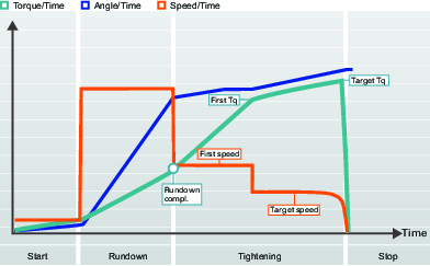
The table below lists all the parameters for the Quick step tightening strategy. Some parameters are mandatory, some are optional and some are conditional.
The conditional parameters are not shown in the configuration menu if the condition is not valid, this is also the case when certain functions are disabled.
Parameters for a torque value as the final target
Parameter name | Condition | Description | Default value |
|---|---|---|---|
Target |
| Torque or Angle can be selected from a shortcut menu. |
|
First torque | Target = torque |
|
|
First speed |
| First speed can be Automatically or Manually selected. |
|
First speed | First speed = manual | Specifies the tools speed during the first step. |
|
Target speed |
| Target speed can be Automatically or Manually selected. |
|
Target speed | Target speed = manual | Specifies the tools speed during the final step. |
|
Target Torque |
| Defines the target torque of the final step of the tightening. |
|
Torque limits |
| Torque values for max and min can be Automatically or Manually selected. |
|
Torque min | Torque limits = Manual | Torque value for the lower limit. | 95% of target torque |
Torque max | Torque limits = Manual | Torque value for the upper limit. | 120% of target torque |
Angle limits |
| Angle limits is selected from a shortcut menu. Off: No angle limit monitoring. From rundown complete: The monitoring window is set from when the Rundown complete torque value is reached. From first torque: The monitoring window is set from when the First torque value is reached. From torque: The monitoring window is set from when the specific torque value is reached. |
|
Final angle monitoring torque | Angle limits = from torque | Torque value from when the angle limits are monitored. |
|
Angle min | Angle limits = on | Angle value lower limit. | 324° |
Angle max | Angle limits = on | Angle value upper limit. | 396° |
Time min | Angle limits = on | Minimum time for the stage. Range 0 - 99999 ms | 0 ms |
Time max | Angle limits = on | Maximum time for the stage. Range 1 - 99999 ms | 1000 ms |
Measure torque at |
| Max torque value: Measures the highest torque value during the tightening. Value at peak angle: Measures the torque value at the highest angle value. Shutoff: Measures the torque value before starting the stop stage. |
|
Torque compensation |
| On: Compensating the final torque value with the measured torque during rundown at the torque compensation point. Off: No torque compensation value is applied. | Off |
Torque compensation point | Torque compensation = On | The torque compensation point is set by referring back to a specified angle from Rundown complete.
| 45° |
Measure angle to | Angle limits = on | Value at peak torque: Measures the angle value at the maximum torque during the tightening. Max angle value: Measures the maximum angle value during the tightening. Shutoff: Measures the angle value before starting the stop stage.
| |
Premature torque loss detection time | 200 ms | ||
Current monitoring | On: The current monitoring is enabled. Off: The current monitoring is disabled. The current monitor is used as a redundancy check for the measured torque to give reasonable confidence that torque readings are accurate. | ||
Shutoff current high limit. | Current monitor = On | The current value must be above 0 and below tool maximum current. | |
Shutoff current low limit | Current monitor = On | The current value must be above 0 and below the current high limit. |
The table below lists all the parameters for the Quick step tightening strategy. Some parameters are mandatory, some are optional and some are conditional.
The conditional parameters are not shown in the configuration menu if the condition is not valid, this is also the case when certain functions are disabled.
Parameters for an angle value as the final target
Parameter name | Condition | Description | Default value |
|---|---|---|---|
Target |
| Torque or Angle can be selected from a shortcut menu. |
|
First torque | Target = angle |
|
|
First speed |
| First speed can be Automatically or Manually selected. |
|
First speed | First speed = manual | Specifies the tools speed during the first step. |
|
Target speed |
| Target speed can be Automatically or Manually selected. |
|
Target speed | Target speed = manual | Specifies the tools speed during the final step |
|
Torque min | Torque value for the lower limit. | 95% of target torque | |
Torque max | Torque value for the upper limit. | 120% of target torque | |
Target angle |
| Target value for the final step. |
|
Angle limits |
| Auto: Set automatically by the algorithm. Manual: The limits are set manually. |
|
Angle min | Angle limits = Manual | Angle value lower limit | 324° |
Angle max | Angle limits = Manual | Angle value upper limit | 396° |
Time min | Angle limits = Manual | Minimum time for the stage Range 0 - 99999 ms | 0 ms |
Time max | Angle limits = Manual | Maximum time for the stage Range 1 - 99999 ms | 1000 ms |
Measure torque at |
| Max torque value: Measures the highest torque value during the tightening. Value at peak angle: Measures the torque value at the highest angle value. Shutoff: Measures the torque value before starting the stop stage. |
|
Torque compensation |
| On: Compensating the final torque value with the measured torque during rundown at the torque compensation point. Off: No torque compensation value is applied. | Off |
Torque compensation point | Torque compensation = On | The torque compensation point is set by referring back to a specified angle from Rundown complete. | 45° |
Premature torque loss detection time | 200 ms | ||
Current monitoring | On: The current monitoring is enabled. Off: The current monitoring is disabled. The current monitor is used as a redundancy check for the measured torque to give reasonable confidence that torque readings are accurate. | ||
Shutoff current high limit | Current monitoring = On | The current value must be above 0 and below tool maximum current. | |
Shutoff current low limit | Current monitoring = On | The current value must be above 0 and below the current high limit. |
Two Step
The Two step strategy is very similar to the Quick step strategy except that it adds a small time delay between the first step and the final step, to further counteract short-term relaxation effects in the joint.
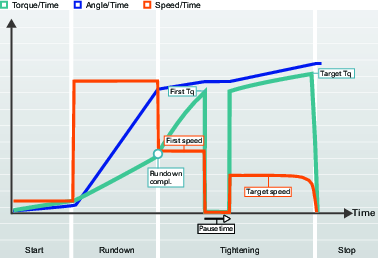
When the First target is reached, the tool makes an immediate stop for a specified time before it continues with the final step. The First torque value and the Pause time should be chosen to improve ergonomics for hand-held tools.
The table below lists all the parameters for the Two step tightening strategy. Some parameters are mandatory, some are optional and some are conditional.
The conditional parameters are not shown in the configuration menu if the condition is not valid, this is also the case when certain functions are disabled.
Parameters for a torque value as the final target.
Parameter name | Condition | Description | Default value |
|---|---|---|---|
Target |
| Torque or Angle can be selected from a shortcut menu |
|
First torque | Target = torque |
|
|
First speed |
| Selected by radio buttons. First speed can be Automatically or Manually selected |
|
First speed | First speed = manual | Specifies the tools speed during the first step |
|
Target speed |
| Selected by radio buttons. Target speed can be Automatically or Manually selected |
|
Target speed | Target speed = manual | Specifies the tools speed during the final step |
|
Pause time | Strategy = Two step | Time between first and final step | 50 ms |
Target Torque |
| Defines the target torque of the final step of the tightening |
|
Torque limits |
| Selected by radio buttons. Torque values for max and min can be Automatically or Manually selected |
|
Torque min | Torque limits = Manual | Torque value for the lower limit | 95% of target torque |
Torque max | Torque limits = Manual | Torque value for the upper limit | 120% of target torque |
Angle limits |
| Angle limits is activated through a shortcut menu. Off: No angle limit monitoring. From rundown complete: The monitoring window is set from when the Rundown complete torque is reached. From first torque: The monitoring window is set from when the First torque is reached. From torque: The monitoring window is set from when the specific torque value is reached. |
|
Final angle monitoring torque | Angle limits = from torque | Torque value from when the angle limits are monitored |
|
Angle min | Angle limits = on | Angle value lower limit | 324° |
Angle max | Angle limits = on | Angle value upper limit | 396° |
Time min | Angle limits = on | Minimum time for the stage Range 0 - 99999 ms | 0 ms |
Time max | Angle limits = on | Maximum time for the stage Range 1 - 99999 ms | 1000 ms |
Measure torque at |
| Selected from a shortcut menu: Max torque value: Measures the highest torque value during the tightening. Value at peak angle: Measures the torque value at the highest angle value. Shutoff: Measures the torque value before starting the stop stage. |
|
Torque compensation |
| Selected from a shortcut menu: On: Compensating the final torque value with the measured torque during rundown at the torque compensation point. Off: No torque compensation value is applied. | Off |
Torque compensation point | Torque compensation = On | The torque compensation point is set by referring back to a specified angle from Rundown complete.
| 45° |
Measure angle to | Angle limits = on | Selected from a shortcut menu: Value at peak torque: Measures the angle value at the maximum torque during the tightening. Max angle value: Measures the maximum angle value during the tightening. Shutoff:Measures the angle value before starting the stop stage.
| |
Premature torque loss detection time | 200 ms | ||
Current monitoring | Selected from a shortcut menu: On: The current monitoring is enabled. Off: The current monitoring is disabled. The current monitor is used as a redundancy check for the measured torque to give reasonable confidence that torque readings are accurate. | ||
Shutoff current high limit. | Current monitor = On | The current value must be above 0 and below tool maximum current. | |
Shutoff current low limit. | Current monitor = On | The current value must be above 0 and below the current high limit. |
The table below lists all the parameters for the Two step tightening strategy. Some parameters are mandatory, some are optional and some are conditional.
The conditional parameters are not shown in the configuration menu if the condition is not valid, this is also the case when certain functions are disabled.
Parameters for an angle value as the final target.
Parameter name | Condition | Description | Default value |
|---|---|---|---|
Target |
| Torque or Angle can be selected from a shortcut menu |
|
First torque | Target = angle |
|
|
First speed |
| Selected by radio buttons. First speed can be Automatically or Manually selected |
|
First speed | First speed = manual | Specifies the tools speed during the first step |
|
Target speed |
| Selected by radio buttons. Target speed can be Automatically or Manually selected |
|
Target speed | Target speed = manual | Specifies the tools speed during the final step |
|
Pause time | Strategy = Two step | Time between first and final step | 50 ms |
Torque min | Torque value for the lower limit | 95% of target torque | |
Torque max | Torque value for the upper limit | 120% of target torque | |
Target angle |
| Target value for the final step |
|
Angle limits |
| Angle limits is activated a through shortcut menu. Auto: Set automatically by the algorithm. Manual: The limits are set manually. |
|
Angle min | Angle limits = Manual | Angle value lower limit | 324° |
Angle max | Angle limits = Manual | Angle value upper limit | 396° |
Time min | Angle limits = Manual | Minimum time for the stage Range 0 - 99999 ms | 0 ms |
Time max | Angle limits = Manual | Maximum time for the stage Range 1 - 99999 ms | 1000 ms |
Measure torque at |
| Selected from a shortcut menu: Max torque value: Measures the highest torque value during the tightening. Value at peak angle: Measures the torque value at the highest angle value. Shutoff: Measures the torque value before starting the stop stage. |
|
Torque compensation |
| Selected from a shortcut menu: On: Compensating the final torque value with the measured torque during rundown at the torque compensation point. Off: No torque compensation value is applied. | Off |
Torque compensation point | Torque compensation = On | The torque compensation point is set by referring back to a specified angle from Rundown complete.
| 45° |
Premature torque loss detection time | 200 ms | ||
Current monitoring | Selected from a shortcut menu: On: The current monitoring is enabled. Off: The current monitoring is disabled. The current monitor is used as a redundancy check for the measured torque to give reasonable confidence that torque readings are accurate. | ||
Shutoff current high limit. | Current monitor = On | The current value must be above 0 and below tool maximum current. | |
Shutoff current low limit. | Current monitor = On | The current value must be above 0 and below the current high limit. |
Three Step
The Three step strategy adds a loosening step between the first step and the final step, to overcome short-term relaxation effects due to embedment, and reduce preload scatter. This is sometimes used to condition the joint. This can be useful in, for example, joints with many adjoining surfaces and will have a greater effect on new parts than on reused ones, due to the smoothing of surfaces, which reduces embedment.
Conditioning the joint is done by tightening the first step to a given torque, First torque, and then releasing the load by turning the nut a specified Conditioning angle and then re-tightening the nut to its Target torque.
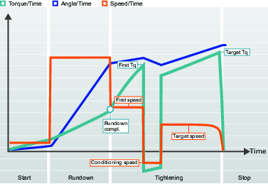
The table below lists all the parameters for the Three step tightening strategy. Some parameters are mandatory, some are optional and some are conditional.
The conditional parameters are not shown in the configuration menu if the condition is not valid, this is also the case when certain functions are disabled.
The table below is valid for Final target = Torque.
When the First target is reached and the conditioning step is entered, the tool makes an immediate stop and reverse before it continues with the final step. This conditioning step may need to be fine-tuned to improve ergonomics for hand-held tools.
Parameters for a torque value as the final target.
Parameter name | Condition | Description | Default value |
|---|---|---|---|
Target |
| Torque or Angle can be selected from a shortcut menu |
|
First torque | Target = torque |
|
|
First speed |
| Selected by radio buttons. First speed can be Automatically or Manually selected |
|
First speed | First speed = manual | Specifies the tools speed during the first step |
|
Conditioning angle | Strategy = Three step | Angle to turn the socket backwards during the conditioning step | 180° |
Conditioning speed | Strategy = Three step | Target speed for the backwards rotation during the conditioning step | 345 rpm |
Target speed |
| Selected by radio buttons. Target speed can be Automatically or Manually selected |
|
Target speed | Target speed = manual | Specifies the tools speed during the final step |
|
Target Torque |
| Defines the target torque of the final step of the tightening |
|
Torque limits |
| Selected by radio buttons. Torque values for max and min can be Automatically or Manually selected |
|
Torque min | Torque limits = Manual | Torque value for the lower limit | 95% of target torque |
Torque max | Torque limits = Manual | Torque value for the upper limit | 120% of target torque |
Angle limits |
| Angle limits is activated through shortcut menu. Off: No angle limit monitoring. From rundown complete: The monitoring window is set from when the Rundown complete torque is reached. From first torque: The monitoring window is set from when the First torque is reached. From torque: The monitoring window is set from when the specific torque value is reached. |
|
Final angle monitoring torque | Angle limits = from torque | Torque value from when the angle limits are monitored |
|
Angle min | Angle limits = on | Angle value lower limit | 324° |
Angle max | Angle limits = on | Angle value upper limit | 396° |
Time min | Angle limits = on | Minimum time for the step Range 0 - 99999 ms | 0 ms |
Time max | Angle limits = on | Maximum time for the step Range 1 - 99999 ms | 1000 ms |
Measure torque at |
| Selected from a shortcut menu: Max torque value: Measures the highest torque value during the tightening. Value at peak angle: Measures the torque value at the highest angle value. Shutoff: Measures the torque value before starting the stop step. |
|
Torque compensation |
| Selected from a shortcut menu: On: Compensating the final torque value with the measured torque during rundown at the torque compensation point. Off: No torque compensation value is applied. | Off |
Torque compensation point | Torque compensation = On | The torque compensation point is set by referring back to a specified angle from Rundown complete.
| 45° |
Measure angle to | Angle limits = on Or final target = angle | Selected from a shortcut menu: Value at peak torque: Measures the angle value at the maximum torque during the tightening. Max angle value: Measures the maximum angle value during the tightening. Shutoff:Measures the angle value before starting the stop step.
| |
Premature torque loss detection time | 200 ms | ||
Current monitoring | Selected from a shortcut menu: On: The current monitoring is enabled. Off: The current monitoring is disabled. The current monitor is used as a redundancy check for the measured torque to give reasonable confidence that torque readings are accurate. | ||
Shutoff current high limit. | Current monitor = On | The current value must be above 0 and below tool maximum current. | |
Shutoff current low limit. | Current monitor = On | The current value must be above 0 and below the current high limit. |
The table below lists all the parameters for the Three step tightening strategy. Some parameters are mandatory, some are optional and some are conditional.
The conditional parameters are not shown in the configuration menu if the condition is not valid, this is also the case when certain functions are disabled.
Parameters for a torque value as the final target.
Parameter name | Condition | Description | Default value |
|---|---|---|---|
Target |
| Torque or Angle can be selected from a shortcut menu |
|
First torque | Target = angle |
|
|
First speed |
| Selected by radio buttons. First speed can be Automatically or Manually selected |
|
First speed | First speed = manual | Specifies the tools speed during the first step |
|
Conditioning angle | Strategy = Three step | Angle to turn the socket in reverse during the conditioning step | 180° |
Conditioning speed | Strategy = Three step | Target speed for the reverse rotation during the conditioning step | 345 rpm |
Target speed |
| Selected by radio buttons. Target speed can be Automatically or Manually selected |
|
Target speed | Target speed = manual | Specifies the tools speed during the final step |
|
Torque min | Torque value for the lower limit | 95% of target torque | |
Torque max | Torque value for the upper limit | 120% of target torque | |
Target angle |
| Target value for the final step |
|
Angle limits |
| Angle limits is activated through shortcut menu. Auto: Set automatically by the algorithm. Manual: The limits are set manually. |
|
Angle min | Angle limits = Manual | Angle value lower limit | 324° |
Angle max | Angle limits = Manual | Angle value upper limit | 396° |
Time min | Angle limits = Manual | Minimum time for the step Range 0 - 99999 ms | 0 ms |
Time max | Angle limits = Manual | Maximum time for the step Range 1 - 99999 ms | 1000 ms |
Measure torque at |
| Selected from a shortcut menu: Max torque value: Measures the highest torque value during the tightening. Value at peak angle: Measures the torque value at the highest angle value. Shutoff: Measures the torque value before starting the stop step. |
|
Torque compensation |
| Selected from a shortcut menu: On: Compensating the final torque value with the measured torque during rundown at the torque compensation point. Off: No torque compensation value is applied. | Off |
Torque compensation point | Torque compensation = On | The torque compensation point is set by referring back to a specified angle from Rundown complete.
| 45° |
Premature torque loss detection time | 200 ms | ||
Current monitoring | Selected from a shortcut menu: On: The current monitoring is enabled. Off: The current monitoring is disabled. The current monitor is used as a redundancy check for the measured torque to give reasonable confidence that torque readings are accurate. | ||
Shutoff current high limit. | Current monitor = On | The current value must be above 0 and below tool maximum current. | |
Shutoff current low limit. | Current monitor = On | The current value must be above 0 and below the current high limit. |
Four Step Tightening Strategy
The four step tightening strategy is divided into separate steps, that can be switched On or Off, to customize the tightening task.
Controller features, such as the Low Reaction Tightening Strategies and controller-wide functions among others, require licenses distributed through the Functionality Management System (FMS). Whereas configuration of features is possible without specific licenses, the assignment and use of those features will require the correct license to be installed on the controller. Please refer to Licenses (FMS) for more detailed information on licenses.
Each step has a target value and may monitor other values , this is divided up as follows:
Step | Function |
|---|---|
Start | The start step is used to engage the threads and to detect if a tightening has already occurred. |
Rundown | The rundown step is used to run down a screw to the snug level. |
Tightening | The tightening step is used to tightening the screw to a defined torque level, and may be divided into several steps. This final target value may be either a target torque or a target angle. |
Stop | The stop step is to finalize the tightening in an ergonomic way. |
Example 1: If the start and rundown steps are used to tighten a screw to the snug level, a final tightening can be made in a later step.
Example 2: If the tightening steps are used in a previous snug level tightening, a final assembly can be made to tighten the joint to the final target value.
Parameter definition
Different parameters control the four step tightening. To illustrate the parameters and their position they are shown in the combined speed-over- time curve, angle-over-time curve and torque-over-time curve.
The graphical representation is used in the documentation to describe the configuration setting and the interpretaion of the parameter values. The graphs are not used in any GUI.
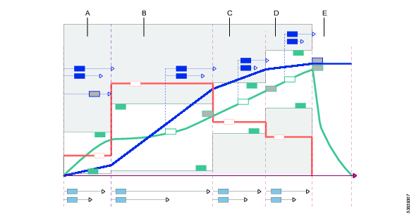
A | Start stage |
B | Rundown stage |
C | Tightening stage: First step |
D | Tightening stage: Final step |
E | Stop stage |
Parameters for Four Step Tightening - Start Stage
The time, torque and angle are monitored during the start step. This step has an angle as target.
The graphical representation is used in the documentation to describe the configuration setting and the interpretation of the parameter values. The graphs are not used in any GUI.
The step is defined from trigger pressed until the specified target angle is reached.
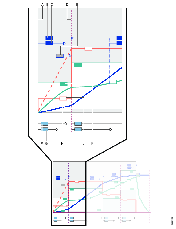
A | Trigger pressed |
B | Angle max (monitor) |
C | Angle min (monitor) |
D | End of start step |
E | Target angle for start step |
F | Time min (monitor) |
G | Time max (monitor) |
H | Angle curve |
J | Speed curve |
K | Torque max value (monitor) |
The tables list all available parameters. Some parameters are only available and visible for certain functions.
Parameter | Description | Default value |
|---|---|---|
Direction | Rotation direction for the tightening. CW: Clockwise CCW: Counter clockwise | CW |
Current monitoring | Off: Current monitoring is disabled and the tool torque is measured by the torque sensor. On: the current is measured at final torque target and converted to a torque value. The calculated torque is compared to the measured torque. If the difference is within 10%, the tightening is considered OK | |
True angle compensation | Switch with On or Off position. | Off |
Negative | Only visible if True angle compensation = On. Defines the maximum negative rotation of the tool. If the value is exceeded the tightening is terminated and an error is reported. This is expressed in a numeric angle value. | 30 |
Positive | Only visible if True angle compensation = On. Defines the maximum positive rotation of the tool. If the value is exceeded the tightening is terminated and an error is reported. This is expressed in a numeric angle value. | 30 |
Attachment tuning enabled | Yes No | No |
Parameter | Description | Default value |
|---|---|---|
Soft start | On: The soft start allows a smooth start at slow speed. It is used to engage the thread. Off: The tool speed ramps up to the rundown speed as quickly as possible. | On |
Speed | Defines the speed during Soft start. | 34 |
Angle | Target angle for the step. End of step is defined at this point, when the target has been reached. | 90 |
Angle min | Monitors the angle value and checks that the result is within the limit. | 70 |
Angle max | Monitors the angle value and checks that the result is within the limit. | 110 |
Torque min | Defines the lower torque limit during Soft start. If Torque min falls below the limit, the tightening is aborted and an error message is issued. The tightening will be considered NOK. | 0.00 |
Torque max | Defines the upper torque limit during Soft start. If Torque max is exceeded, the tightening is aborted and an error message is issued. The tightening will be considered NOK. | 1.25 |
Time min | Minimum time for the step. measured from trigger pressed. Expressed in a numeric millisecond value. | 100.00 |
Time max | Maximum time for the step. measured from trigger pressed. Expressed in a numeric millisecond value. | 500.00 |
Use attachment tuning | Yes No | No |
Gear ratio | Only visible if Use attachment tuning is set to Yes. Min/Max values: 0.5/4.0 Gear ratio is needed to compensate the angle and torque. The Gear ratio will affect the max speed and max torque of the tool. When switching between the parameter Use attachment tuning Yes/No, the values of the Gear ratio are not reset to default values. | 1.00 |
Efficiency tuning | Only visible if Use attachment tuning is set to Yes. Min/Max values: 0.5/1.0 Sets the efficiency loss for the attachment. Gear ratio combined with Efficiency tuning is needed to compensate the torque. When switching between the parameter Use attachment tuning Yes/No, the values of the Efficiency tuning are not reset to default values. | 1.00 |
Parameters for Four Step Tightening - Rundown Stage
The Rundown step is from thread engagement until the screw head reaches the snug level. During rundown; time, torque and angle are monitored. The target value for the step is when the Rundown complete torque level is reached.
The graphical representation is used in the documentation to describe the configuration setting and the interpretation of the parameter values. The graphs are not used in any GUI.
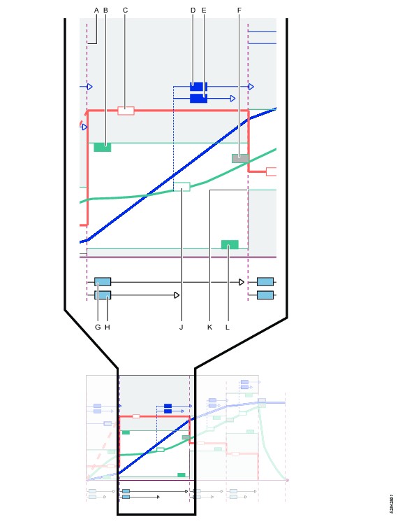
A | Start of Rundown step |
B | Maximum torque level (monitor) |
C | Speed curve |
D | Minimum angle (monitor); Measured from Rundown angle monitoring torque |
E | Maximum angle (monitor); Measured from Rundown angle monitoring torque |
F | Rundown complete torque value |
G | Time max (monitor) |
H | Time min (monitor) |
J | Torque curve and Rundown angle monitoring torque reference point |
K | End of rundown step, when target value is reached |
L | Minimum torque level (monitor) |
Parameter | Description | Default value |
|---|---|---|
Rundown | Switch with On or Off position. If the switch is in the Off position, the step is not executed and all other parameters are invisible and are ignored. If both the start step and the rundown step are switched off, a final tightening can be performed as a separate task. | On |
Parameter | Description | Default value |
|---|---|---|
Rundown speed | If Max position, the speed is the set to full tool capability. If Manual position, the speed is set manually. | Max |
Rundown speed (parameter entry box) | This parameter entry box is only visible when Manual speed setting is selected. The spindle rotation speed during the step. | 690 rpm |
Torque min (monitor) | Minimum torque value during the step. | 0 Nm |
Torque max (monitor) | Maximum torque value during the step. | 6 Nm |
Rundown angle monitoring torque | A specified torque value. From this point in time the angle monitoring starts. | 0 Nm |
Angle min (monitor) | Minimum spindle rotation for the step. Measured from Rundown angle monitoring torque. | 100 degree |
Angle max (monitor) | Maximum spindle rotation for the step. Measured from Rundown angle monitoring torque. | 5000 degree |
Time min (monitor) | Minimum time for the step. Measured from the start of the step. | 10 ms |
Time max (monitor) | Maximum time for the step. Measured from the start of the step. | 5000 ms |
Rundown complete torque | Defines the target torque for the rundown step. End of step is defined at this point, when the target value is reached. | 5 Nm |
Parameters for Four Step Tightening - Tightening Stage
The tightening step is divided into two steps, first step and final step. The First tightening step is from rundown complete until the First torque target level is reached. During the first tightening; time, torque and angle are monitored.
The graphical representation is used in the documentation to describe the configuration setting and the interpretation of the parameter values. The graphs are not used in any GUI.
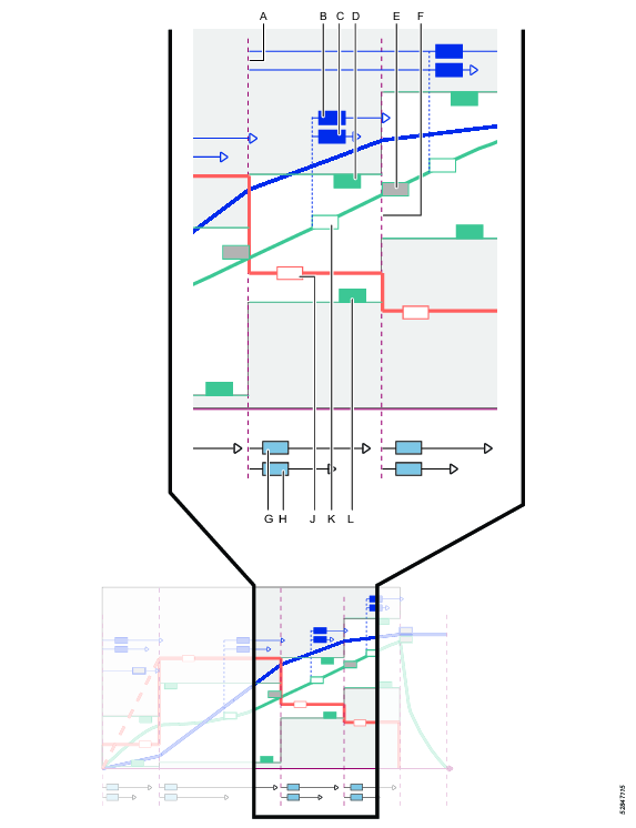
A | Start of theFirst tightening step in the tightening step |
B | Min angle (monitor); Measured from First angle monitoring torque |
C | Max angle (monitor); Measured from First angle monitoring torque |
D | Maximum torque level (monitor) |
E | First tightening torque value; Defines the target value and the end of the step |
F | End of step |
G | Time max (monitor) |
H | Time min (monitor) |
J | Speed curve |
K | Torque curve and First angle monitoring torque reference point |
L | Minimum torque (monitor) |
Parameter | Description | Default value |
|---|---|---|
First step | If the switch is in the Off position, the step is not executed and all other parameters are invisible and are ignored. | On |
First torque | Defines the target torque for the step. End of step is defined at this point, when the target is reached. | 20 Nm |
First speed | If Auto position, the speed is set automatically. If Manual position, the speed is set manually. | Auto |
First speed (parameter entry box) | This parameter entry box is only visible when Manual speed setting is selected. The spindle rotation speed during the step. | 345 rpm |
First torque min | Minimum torque value during the step. | 19 Nm |
First torque max | Maximum torque value during the step. | 21 Nm |
First angle monitoring torque | A specified torque value. From this point in time the angle monitoring starts. | 5 Nm |
First angle min | Minimum spindle rotation for the step. Measured from First angle monitoring torque. | 0 degree |
First angle max | Maximum spindle rotation for the step. Measured from First angle monitoring torque. | 500 degree |
Time min | Minimum time for the step. Measured from the start of the step. | 10 ms |
Time max | Maximum time for the step. Measured from the start of the step. | 500 ms |
Measure torque at | Max torque value Value at peak angle Value at shut off |
Parameters for Four Step Tightening - Final Tightening Stage
The tightening step is divided into two steps, first step and final step. The First tightening step is from rundown complete until the First torque target level is reached. During the first tightening; the time, torque and angle are monitored. The Final tightening step is from First torque until the final target level is reached. During the final tightening; the time, torque and angle are monitored. The target value for the step is either when the Target torque or the Target angle level is reached.
The graphical representation is used in the documentation to describe the configuration setting and the interpretation of the parameter values. The graphs are not used in any GUI.
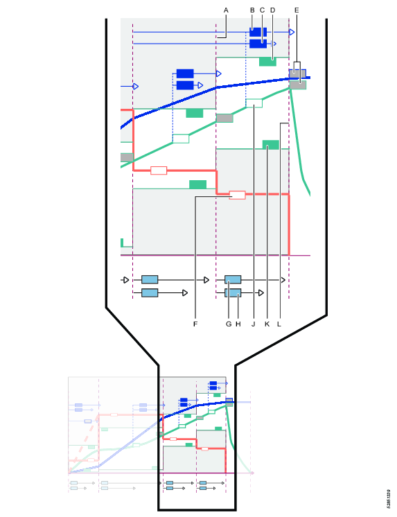
A | Start of Final tightening step |
B | Minimum angle (monitor); Measured from a selectable reference point |
C | Maximum angle (monitor); Measured from a selectable reference point |
D | Maximum torque level (monitor) |
E | Final target is either the Target torque or the Target angle; angle reference point is measured from a selectable reference point |
F | Speed curve and speed value |
G | Time maximum (monitor) |
H | Time minimum (monitor) |
J | Torque curve and Final angle monitoring torque reference point |
K | Minimum torque (monitor) |
L | End of step |
The parameters differ between Target torque and the Target angle selection.
Parameter | Description | Default value |
|---|---|---|
Target | Drop-down selection of final target. Torque: The final target in the tightening step is a torque value. Angle: The final target in the tightening step is an angle value. |
|
Target speed | Switch with Manual or Auto position. If the switch is in the Auto position, then the speed is set automatically by the tightening algorithm. If the switch is in the Manual position, then the speed is set manually. | Auto |
Target speed (parameter) | This parameter is only visible when theManual speed setting is selected. The spindle rotation speed during the step. This is expressed in a numeric value in rpm. | 113 |
Target torque | Defines the target torque for the step. End of step is defined at this point, when the target has been reached. |
|
Torque limits | Switch with Manual or Auto position. The switch is only visible if the final target value is set to Torque. If the switch is in the Auto position, the torque limits are set automatically by the tightening algorithm. If the switch is in the Manual position, the maximum and minimum torque limits are set manually. | Auto |
Torque min | The parameter is only visible if Manual torque limits have been selected. Minimum torque value during the step. This is expressed in a numeric torque value. | Final target torque - 5% |
Torque max | The parameter is only visible if Manual torque limits have been selected. Maximum torque value during the step. This expressed in a numeric torque value. | Final target torque + 20% |
Angle limits | Drop-down menu to select the reference point for angle limits.
|
|
Final angle monitoring torque | A specified torque value. From this point the angle monitoring starts. The value must be higher than the First torque value and lower then Final target torque. |
|
Final angle min | Minimum spindle rotation for the step. Reference point for the measurement is selected from the drop-down menu Angle limits. This is expressed in a numeric degree value. | 324 degrees |
Final angle max | Maximum spindle rotation for the step. Reference point for the measurement is selected from the drop-down menu Angle limits. This is expressed in a numeric degree value. | 396 degrees |
Time min | Minimum time for the step. Measured from the start of the step. This is expressed in a numeric millisecond value. | 10 ms |
Time max | Maximum time for the step. Measured from the start of the step. This is expressed in a numeric millisecond value. | 1000 ms |
Measure torque at | Max torque value Value at peak angle Value at shutoff | Max torque value |
Measure angle to | Value at peak torque Max angle value Value at shutoff | Max angle value |
The values specified in the table below assumes that the first step of the tightening step is switched on.
Parameter | Description | Default value |
|---|---|---|
Target | Torque: The final target in the tightening step is a torque value. Angle: The final target in the tightening step is an angle value. |
|
Target speed | If in Auto position, the speed is set automatically by the tightening algorithm. If in Manual position, the speed is set manually. | Auto |
Target speed (parameter) | This parameter is only visible when the Manual speed setting is selected. The spindle rotation speed during the step. | 113 |
Torque min | The parameter is only visible if Manual torque limits have been selected. Minimum torque value during the step. Must be above First target torque. |
|
Torque max | The parameter is only visible if Manual torque limits have been selected. Maximum torque value during the step. |
|
Min torque at final supervision | The value is used to monitor and to ensure that a minimum torque level is maintained during the entire final step. The level is normally set below the final torque minimum but higher than the rundown torque level. It can be used to verify that the screw is not broken during the tightening. | 18 Nm |
Target angle | Defines the target angle for the step. The reference point for the target angle is measured from the end of the previous activated step or step. End of step is defined at this point, when the target has been reached. | 360 degrees |
Angle limits | Drop-down menu to select the reference point for angle limits.
| Manual |
Final angle monitoring torque | A specified torque value. From this point the angle monitoring starts. The reference point depends on previous activated steps or steps. |
|
Angle min | Minimum spindle rotation for the step. Reference point for the measurement is selected from the drop-down menu Angle limits. This is expressed in a numeric degree value. | 324 degrees |
Angle max | Maximum spindle rotation for the step. Reference point for the measurement is selected from the drop-down menu Angle limits. | 396 degrees |
Time min | Minimum time for the step. Measured from the start of the step. | 10 ms |
Time max | Maximum time for the step. Measured from the start of the step. | 1000 ms |
Measure torque at | Max torque value Value at peak angle Value at shutoff | Max torque value |
Measure angle to | Value at peak torque Max angle value Value at shutoff | Max angle value |
NOK on trigger lost | On Off | On |
Parameters for Four Step Tightening - Stop Stage
Soft-stop is used to finish the stop step in an ergonomic way.
Parameter | Description | Default value |
|---|---|---|
Soft-stop | Drop-down menu with On or Off selection. If soft stop is set to Off, the tool will stop fast as possible after the final target has been reached. If the tools speed is reduced as fast as possible, it can cause a reaction force. A reaction force can corrupt an angle measurement, which in turn can be compensated with a True-angle compensation. If soft stop is set to On, the tool will finish the stop step in an ergonomic way. | Off |
External Result
External result is a strategy used when an OK tightening is indicated by an external digital signal (and not by torque or angle values measured during tightening). This external signal can be provided through any means that can provide a digital signal into the Power Focus 6000 (e.g through the I/O bus).
When the signal is sent, the Result view will show the value of the Target parameter provided in the tightening program (specified torque value, angle value, or text string). These (torque and angle) values do not represent actual measured values, but only inserted text.
Select a controller in the Plant structure workspace
. Go to Tightening
.The Tightening workspace shows a list of tightening programs.
Double-click on the name of a tightening program to configure the tightening program to be an external result strategy or create a new external result strategy by selecting the Add command button.
Parameter | Description | Default value |
|---|---|---|
Torque <Target torque> | Numerical value for desired displayed target torque value. A signal could for example come from a Click Wrench and display <Target torque>. | 0.00 |
Angle <Target angle> | Numerical value for desired displayed target angle value. A signal could for example come from a Click Wrench and display <Target angle>. | 360° |
Text | Alphanumerical string for desired displayed text. For example: "Oil has been changed". |
|
The External result is being logged and will end up in Live result view and in Historical results.
In order to use External OK, the Virtual Station must use the tightening program External Result strategy as an assigned task and also a tool to be assigned to the Virtual Station. The tool can be either a physical tool or a virtual external tool.
Results from External Tools
It is possible to report results from an external tool or application not connected to the controller. This feature provides the possibility to define an external tool which can be defined as a logical or virtual tool which uses the tightening strategy External result and assign it to a virtual station in place of a real tool.
Setting Up an External Tool
Select a controller in the Plant structure window
.Go to Settings
.The workspace area displays the Settings menus.
Select Add in the External Tool menu and set Enabled to On.
Setting Enabled to Off, disconnects the external tool without deleting it and can be enabled when required.
It is possible to create up to 10 External Tool configurations per controller.
Enter the Model, Serial number and the Description of the external tool.
The Serial Number is a mandatory parameter and the maximum number of characters allowed is 32.
To delete the external tool, select the checkbox External Tool Configuration and select Delete.
Push changes
and the external tool will be visible in the Tool
tab and also in the controller.
Configuring the External Results Without Tool Connected
In the Plant structure workspace select a controller
. Select the Virtual Station tab
.Select the external tool in the Tool menu.
Assign the task with the external result strategy to the virtual station the Task menu and push changes
.
Pulsing Tool Strategies
The strategy can be selected if the controller software version supports the tightening program. Pulsing tools can achieve a higher torque compared to normal rotating tools.
Pulse Tightening Program
Start
During the start step, the tool rotates in a speed mode without any pulsing.
Parameter name | Description |
|---|---|
Soft start | Enables setting of the tool’s speed, angle and maximum torque to facilitate the bolt entering the thread. Selected by radio buttons. Off: Soft start is turned off. On: Soft start is turned on. |
Speed | Defines the speed during the soft start. |
Time | Defines the Soft start duration. |
Angle | Defines the target angle to turn the spindle for the bolt to enter the thread. |
Torque max | Defines the upper torque limit during the soft start. If Torque max is exceeded, the tightening is considered NOK. |
Rehit detection | Early: Terminates the tightening immediately when an already tightened screw/bolt is detected. The tightening will be considered as NOK. Requires that Soft start is activated. Complete: Even though an already tightened screw/bolt is detected, the tightening is not terminated until all tightening steps have been executed. The tightening will be considered as NOK. To make a rehit detection when Soft start is not activated, the Rehit detection Complete option must be selected. Rehit detection Complete will not terminate the tightening until all tightening steps have been executed. The tightening will be considered a rehit if the speed fails to reach half the rundown speed, a rehit error is then indicated. Off: No rehit detection will be performed. Combination Soft start = Off and Rehit = Early is not allowed. |
Positive | The TrueAngle compensation can detect tool rotation and make angle compensations within the set limits. |
Negative | The TrueAngle compensation can detect tool rotation and make angle compensations within the set limits. |
Use attachment tuning | Attachment tuning is selected by radio buttons. |
Gear ratio | Socket rotation speed = Tool speed / gear ratio. |
Efficiency tuning | For example 0.9 means 10% efficiency loss. |
Rundown
During rundown, the tool can use either speed mode, with a constant motor speed, or pulse mode. The selection is made depending on the encountered torque and the given torque limits within the configuration.
Parameter name | Description |
|---|---|
High-speed rundown | The rundown step can be done in high-speed in order to minimize the time, without overshooting. This is achieved by letting the tool run at a higher speed for a specified angle length. When the angle has been reached, the speed will change to the lower speed specified in Rundown speed parameter. Only available for SRB tools. Length: Default 3600°, max 99999° Speed: Tool max speed must be higher than Rundown speed (rpm). |
Rundown speed | Rundown speed can be set to either Max or Manual. If Rundown speed is set to Manual; enter the tool speed in rpm. |
Rundown angle limits | Off: Rundown angle limits is turned off. From Trigger: Rundown angle limits is turned On. The system starts to monitor the tightening angle as soon as the tool trigger is pressed and reports if angle limits are violated. From torque: Rundown angle limits is turned On. The system starts to monitor the tightening angle from the specified torque value and reports if angle limits are violated. |
Rundown angle monitoring torque | Torque value from where Rundown angle limits are set. |
Angle min | Angle value for lower angle limit from starting point. |
Angle max | Angle value for upper angle limit from starting point. |
Time min | Minimum time for the step. |
Time max | Maximum time for the step. |
Rundown pulse limits | Selected from a shortcut menu: Off: Rundown pulse limits is turned off. From Trigger: Rundown pulse limits is turned On. The system starts to monitor the pulses as soon as the tool trigger is pressed and reports if the pulse limits are violated. From torque: Rundown pulse limits is turned On. The system starts to monitor the pulses from the specified torque value and reports if the pulse limits are violated. |
Rundown pulse monitoring torque | Torque value from where the Rundown pulse limits monitor starts. The value must be set to a value greater than Continuous max torque. |
Pulses min | Minimum number of pulses to reach the Rundown complete torque value. |
Pulses max | Maximum number of pulses to reach the Rundown complete torque value. |
Rundown complete torque | Defines the torque value for when snug is reached and the rundown is completed. The program proceeds with the tightening and starts with pulse mode, if not already done so during rundown. |
Tightening
Parameter name | Description |
|---|---|
Target torque | Final target torque for the tightening. |
Pulse Energy | The Pulse energy delivered in the action pulse expressed in a percentage of the maximum energy that the tool can deliver in each pulse. |
Reaction force tuning factor | The energy delivered by the tool expressed in a percentage value. The reaction force tuning factor is based on the action energy and results in a comfortable reaction. |
Residual torque correlation factor | The term Residual torque correlation factor is similar to a calibration and adjusts between the dynamic torque, measured in the electrical tool, and the residual torque, measured by a control tool. |
Torque limits | Limits can be Automatically or Manually selected. |
Torque min | Minimum torque for the step. |
Torque max | Maximum torque for the step. |
Angle limits | Off:Angle limits is turned off. From Rundown complete: Angle limits is turned On. The system starts to monitor the tightening angle as soon as Rundown complete is reached and reports if angle limits are violated. From torque: Rundown angle limits is turned On. The system starts to monitor the tightening angle from the specified torque value and reports if angle limits are violated. |
Rundown angle monitoring torque | Torque value from where Rundown angle limits monitoring starts. |
Angle min | Angle value for lower angle limit from the starting point. |
Angle max | Angle value for the upper angle limit from starting point. |
Time min | Minimum time for the step. |
Time max | Maximum time for the step. |
Pulse limits | Off: No pulse limit monitoring. From rundown complete: The monitoring starts when the Rundown complete torque is reached. From torque: The monitoring starts when the specific torque value is reached. |
Final pulse monitoring torque | Torque value from when the pulse limits are monitored. |
Pulses min | Minimum number of pulses to reach the final target. |
Pulses max | Maximum number of pulses to reach the final target. |
Premature torque loss detection time | A constant increase in torque is assumed when moving from rundown to tightening. A socket slip off, or a broken screw head can cause the torque to decrease. This may be detected in a monitoring window. |
Pulse Tightening with Direct Driven Electrical Tools
The principle below is applicable for direct driven electrical tools. It is applicable to the Atlas Copco SRB series of tools.
The pulse tightening uses a technique of pulsing the electrical current in the motor and has two distinct features:
An action current that adds positive torque in the tightening direction.
A reaction current that creates a comfort reaction by applying a reverse torque.

A | Action pulse to apply tightening force. |
B | Reaction pulse for comfort |
The figure shows the general principle of a current pulse tightening strategy. The detailed curve depends on the tool type and the tightening algorithm.
The pulse period consists of two phases as shown in the figure with an action current and a reaction current. Each action pulse adds torque to the tightening until the final target is reached. Each reaction pulse creates a counterforce that provides a comfortable reaction.
The energy level of the action phase and the reaction phase are configurable parameters. The combination of these two parameters creates an efficient tightening combined with operator comfort.
Tightening using the TensorPulse Program
The principle below is applicable for direct driven electrical tool. It is applicable to the Atlas Copco SRB series of tools.
After each pulse period the resulting torque in the screw is increased. After a series of pulses, the final torque target is reached.
A | Maximum positive energy in pulse N |
B | Maximum positive energy in pulse N+1 |
C | Increase in energy (torque) |
The energy level in the action phase and reaction phase are user configurable parameters. The combination of these two parameters creates an efficient tightening combined with operator comfort. It is possible to set the amount of energy in the two phases as a percentage of the maximum energy that can be delivered in each period:
Pulse energy; The amount of energy that is applied to each positive pulse as a percentage of the maximum energy that can be applied in the pulse period. The value is between 10-100%.
Reaction force retention factor; The amount of energy that is applied to each reactive pulse as a percentage of the maximum energy that can be applied in the pulse period. The value is between 0-75%.
A | Reduced positive energy in pulse N |
B | Reduced positive energy in pulse N+1 |
C | Resulting curve for torque build up using maximum pulse energy. |
D | Resulting curve for torque build up using reduced pulse energy. |
A small Pulse energy (reduced energy) requires more pulses to reach the target torque as the torque is increased in smaller steps. Smaller steps provides better accuracy to terminate the tightening when the target is reached. Smaller pulses decrease tool movement and increases operator comfort.
A correctly tuned Reaction force retention factor will create the desired operator comfort. If the factor is too high the operator feels a clockwise rotation of the tool. If the factor is too low, the operator feels a counter clockwise rotation of the tool.
In an ideal configuration, the reaction energy does not create any loosening force. If the amount of pulses to reach the target value increases, the value is set too high and a small loosening occurs at each pulse.
The optimum values for the Pulse energy and the Reaction force retention factor need to be tuned for optimum performance of the tool and for best operator comfort.
STwrench Strategies
STwrench introduction
The STwrench is a torque wrench that can be used both for production and for quality control. Configurations of parameters can be made via the controller or via ToolsTalk 2.
The STwrench can be connected to a controller using a wireless connection. The STwrench can be configured through the controller GUI, the web GUI or the ToolsTalk 2 GUI.
The STwrench is configured in the Tightening section and uses the same workspace and menus as the other tightening strategies.
The STwrench has a Rapid Backup Unit (RBU). The RBU defines the wrench function and stores the tightening programs. The controller supports the RBU of the type Production.
The STwrench End-fitting tool (socket) contains a RFID TAG with a programmable number. The wrench uses this number to automatically recognize the tool and which program can be used. The RFID TAG also stores the torque and angle correction coefficients.
The STwrench has several programs for production tightening and for quality control. More details about the programs, strategies and the parameters are given in the STwrench user guide.
The STwrench can only support tightening programs which are supported by the tool, that is, Wrench-production and Wrench-quality.
Controller features, such as tightening strategies and controller-wide functions among others, require licenses distributed through the Functionality Management System (FMS). Whereas configuration of features is possible without specific licenses, the assignment and use of those features will require the correct license to be installed on the controller. Please refer to Licenses (FMS) for more detailed information on licenses.
STwrench Start Step Parameters
The parameters shown in the tables are available if one of the STwrench strategies are used. There are several combinations of strategies. Some of the parameters are only available for certain strategies and may not be visible in other strategies.
Parameter rules are automatically checked. If a violation occurs, the error indicator is displayed beside the incorrect parameters. Select the error indicator to display more information about the error.
Switching between strategies can result in the error indicator being shown. This indicates that the chosen combination is invalid, and needs to be corrected.
For more information about the STwrench, see the STwrench User Guide (printed matter number 9836 4134 01).
Parameter name | Condition | Description | Default value |
|---|---|---|---|
Tag number | On: after enabling TAG Check switch (Configurations > Tool Configuration > TAG Check > On), a correct TAG number is required to run the tightening program. Off: The TAG number is not checked. | Off | |
Required tag number | Tag number = On | The required TAG number for this tightening program. | 1 |
Rehit detection | The parameter options are: Complete or Off . | Off | |
Torque correction coefficient | In certain cases extensions may be needed to fit the application. In this case the wrench measurement must be compensated to show a correct value. For more information about to calculate the correction coefficient, see the STwrench User Guide (printed matter number 9836 4134 01). The parameter is stored in the RFID TAG in the End-fitting tool. | 1.0 | |
Angle correction | In certain cases extensions may be needed to fit the application. In this case the wrench measurement must be compensated to show a correct value. To calculate the correction coefficient, please refer to the STwrench user guide. The parameter is stored in the RFID TAG in the End-fitting tool. | 0° |
STwrench Rundown Step Parameters
The parameters shown in the tables are available if one of the STwrench strategies are used. There are several combinations of strategies. Some of the parameters are only available for certain strategies and may not be visible in other strategies.
Parameter rules are automatically checked. If a violation occurs, the error indicator is displayed beside the incorrect parameters. Select the error indicator to display more information about the error.
Switching between strategies can result in the error indicator being shown. This indicates that the chosen combination is invalid, and needs to be corrected.
For more information about the STwrench, see the STwrench User Guide (printed matter number 9836 4134 01).
Rundown complete is in the STwrench documentation defined as Cycle start , this is when the tightening step begins.
Parameter name | Description | Default value |
|---|---|---|
Rundown complete torque | Definition of the Rundown complete point | Depends on the smarthead minload (usually 5% of nominal torque) in Nm |
Ratchet time | 5000 ms |
STwrench Tightening Step Parameters
The parameters shown in the tables are available if one of the STwrench strategies are used. There are several combinations of strategies. Some of the parameters are only available for certain strategies and may not be visible in other strategies.
Parameter rules are automatically checked. If a violation occurs, the error indicator is displayed beside the incorrect parameters. Select the error indicator to display more information about the error.
Switching between strategies can result in the error indicator being shown. This indicates that the chosen combination is invalid, and needs to be corrected.
For more information about the STwrench, see the STwrench User Guide (printed matter number 9836 4134 01).
Parameter name | Condition | Description | Default value |
|---|---|---|---|
Target | Select the target from the drop-down menu. Torque, Angle, Torque or Angle. | Torque | |
Target Torque |
| Defines the target torque for tightening step. | 0 Nm |
Target Angle | Target = Angle | Defines the target angle for tightening step. | 360° |
Torque limits | Target = Torque | Selection made by a switch. Auto or Manually position. |
|
Torque min | Torque limits = Manual | Torque value for the lower limit | 0 Nm |
Torque max | Torque limits = Manual | Torque value for the upper limit | 0 Nm |
Angle limits | Target = Angle | Selected from a drop-down menu. The parameter options are: Auto or Manually. Angle values for max and min can be or selected | |
Angle limits | Target = Torque | Selected from a drop-down menu. The parameter options are: Off: No angle limit monitoring. From rundown complete: The monitoring window is set from when the Rundown complete torque is reached. From torque: The monitoring window is set from when the specific torque value is reached. | |
Final angle monitoring torque |
| Torque value from when the angle limits are monitored | 18.75 Nm |
Angle min | Angle limits = on or manually | Angle value lower limit | 324° |
Angle max | Angle limits = on or manually | Angle value upper limit | 396° |
Angle search limit | Angle limits = manually | ||
Measure torque at |
| Selected from a drop-down menu. The parameter options are: Max torque value Value at peak angle |
|
NOK on final less than target |
| Selection made by a switch. On or Off position. | Off |
Change bolt limit |
| 50 Nm |
Parameter name | Condition | Description | Default value |
|---|---|---|---|
Torque compensation point | Torque compensation = On | 0° | |
PCT distance | Torque compensation = On | 360° | |
PVT interval | Torque compensation = On | 180° | |
Delay monitoring | Torque compensation = On | 0° | |
Torque min | Torque compensation = On | Torque value for the lower limit | 1 Nm |
Torque max | Torque compensation = On | Torque value for the upper limit | 20 Nm |
Compensation value | Torque compensation = On | Selected from a drop-down menu. The parameter options are: Average torque Peak torque |
STwrench Stop Step Parameters
The parameters shown in the tables are available if one of the STwrench strategies are used. There are several combinations of strategies. Some of the parameters are only available for certain strategies and may not be visible in other strategies.
Parameter rules are automatically checked. If a violation occurs, the error indicator is displayed beside the incorrect parameters. Select the error indicator to display more information about the error.
Switching between strategies can result in the error indicator being shown. This indicates that the chosen combination is invalid, and needs to be corrected.
For more information about the STwrench, see the STwrench User Guide (printed matter number 9836 4134 01).
Parameter name | Condition | Description | Default value |
|---|---|---|---|
End cycle time | It is applied when torque goes below the cycle start and gets to the third percentage value set on the STwrench LEDs. | 100 ms |
STwrench Loosening
The parameters shown in the tables are available if one of the STwrench strategies are used. There are several combinations of strategies. Some of the parameters are only available for certain strategies and may not be visible in other strategies.
Parameter rules are automatically checked. If a violation occurs, the error indicator is displayed beside the incorrect parameters. Select the error indicator to display more information about the error.
Switching between strategies can result in the error indicator being shown. This indicates that the chosen combination is invalid, and needs to be corrected.
For more information about the STwrench, see the STwrench User Guide (printed matter number 9836 4134 01).
Parameter name | Condition | Description | Default value |
|---|---|---|---|
Loosening limit | If this parameter is set to a value greater than 0, Power Focus checks if a negative torque exceeding this value is applied during the tightening. In that case, the overall status of the tightening is marked as Not OK. This function is started when the wrench reaches the Cycle Start (before starting the tightening, a loosening is allowed and does not produce results). This function is used to detect unwanted loosening at the end of a tightening (for instance, when the wrench is disengaged from the joint). | 0 Nm |
Multistep Tightening Strategy
A Multistep tightening is a tightening done in several steps. The number of steps and the type of the steps vary depending on the tightening to be done. A Multistep tightening program is highly configurable, including monitoring functions and restrictions. A total of ten steps can be added to a Multistep program.
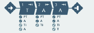
Restrictions are used to make sure the tightening stops if something unexpected occurs. These restrictions could, for example, test that a maximum set torque is not reached or that a part of the multistep tightening does not take too long to run. Every step can have up to four restrictions each. Each step has mandatory step restrictions and optional step restrictions. The mandatory restrictions are included when dragging a new step to the multistep program.
Monitors are used to verify that the tightening was made according to the specification. This can be, for example, angle limits or torque limits. Every step can have up to eight monitors each. Each step has mandatory step monitors and optional step monitors. The mandatory monitors are included when dragging a new step to the multistep program.
Controller features, such as the Low Reaction Tightening Strategies and controller-wide functions among others, require licenses distributed through the Functionality Management System (FMS). Whereas configuration of features is possible without specific licenses, the assignment and use of those features will require the correct license to be installed on the controller. Please refer to Licenses (FMS) for more detailed information on licenses.
Tightening Program Menu

Each row in the list represents one multistep tightening program.
Header | Description |
|---|---|
Check box | Used for selecting a specific tightening program. |
Name | A user-defined name. |
Strategy | Selected strategy for the tightening program. |
Library link | Linked to global library Yes/No. |
Target |
|
Last changed | Time expressed in ToolsTalk 2 time. |
Changed by | Tightening program changed by <user> |
Controller updated | Controller updated, expressed in controller time. |
Controller updated by | Controller updated by <user> |
Approval status | Approval status of the tightening or loosening program |
Command | Description |
|---|---|
Add |
|
Manage |
|
Adding a Multistep Program
Select the Add button. The Create new Tightening program dialog window opens.
Enter tightening program name, index number (only valid for tightenings), operation mode and select tightening strategy Multistep. The tightening program will be issued with the next sequential number in the list of programs, if no active selection of the index is made.
Select the Add button.
The multistep has two sub-tabs Properties, where the different parameters of the program can be entered and Tightening editor, where a program can be created.
Properties Sub-Tab
Properties
Parameter | Description |
|---|---|
Name | A user-defined name for the multistep program. |
Description | Description of the multistep program. |
Parameter | Description |
|---|---|
Type | Tightening or loosening. |
Thread direction | Clockwise (CW) or counter clockwise (CCW) rotational direction. |
Loosening program | Select an existing loosening program to connect to the tightening program. |
Program Start | The multistep tightening program starts when the torque passes the trigger torque value (Nm) for the first time, in order to avoid starting the program by accident. |
True Angle Compensation | Certain tools can detect and measure the tool rotation during tightening. If the tool is rotated during tightening, the angle measurement may be corrupted. This may lead to a faulty tightening if the tool movement is too great. For variations within specified limits, the controller can compensate these rotations and make a correct tightening. This is an additional Licensed Feature, available per Virtual Station. |
Program Restrictions
Parameter | Description |
|---|---|
Maximum Time Limit | Set amount in seconds. This restriction checks the total time for the tightening and if it exceeds the Time High limit the tool is stopped immediately. The time is measured from the start of the program. |
Maximum Torque Limit | This restriction checks the torque and if the measured torque exceeds the Torque High limit the tool is stopped immediately. |
Program Monitors
Parameter | Description |
|---|---|
Angle | Turn angle monitoring On or Off for the entire program. If Active in steps and Trigger Torque are left blank, angle monitoring will start at program start. |
Active in steps | Sets a range of steps the angle monitoring is valid for. If no end step is specified, angle monitoring will stop at the last step of the program that is not a Socket Release step. |
Type | Type of angle monitoring. Choose between:
|
Trigger Torque | Sets the value of the trigger torque for angle monitoring. For STB tools, Trigger Torque will only activate in the tightening direction when executing a tightening program; and only in the loosening direction when executing a loosening program. |
Low Limit | Sets angle monitoring (program) lower limit. |
High Limit | Sets angle monitoring (program) higher limit. |
Parameter | Description |
|---|---|
Torque | Turn angle monitoring On or Off for the entire program. If Active in steps is left blank, torque monitoring will start at program start. |
Active in steps | Sets a range of steps the torque monitoring is valid for. If no end step is specified, torque monitoring will stop at the last step of the program that is not a Socket Release step. |
Type | Type of angle monitoring:
|
Low limit | Sets torque monitoring (program) lower limit. |
High limit | Sets torque monitoring (program) higher limit. |
Validation
During the configuration of tightening programs, the entered values are compared with the tool capability values to prevent parameters being outside the selected limits. User-defined maximum values are useful if many different tools are being used.
Parameter | Description |
|---|---|
Validate against tool values | Use On to set Max Torque and Max Speed manually, or select a specific tool in order to validate against the selected tool's values. When a specific tool is selected, the steps and monitors not supported by the specific tool are indicated by a yellow triangle. |
Max Torque | The maximum limit used in the validation. This is expressed in a numeric torque value. |
Max speed | The maximum limit used in the validation. This is expressed in a numeric rpm value. |
Attachment Tuning
Attachment tuning gives the possibility to compensate for front attachments on the tool. The compensation can be made for each tightening program.
An operator can hot swap attachments and then select a tightening program tuned for that specific attachment.
Parameter | Description |
|---|---|
Use Attachment Tuning | Yes or No |
Gear Ratio | The Attachment gear ratio is needed to compensate the angle. Minimum: 0.5 Maximum: 3.6 Socket rotation speed = Tool speed / gear ratio |
Efficiency Tuning | Attachment gear ratio combined with the Efficiency tuning is needed to compensate the torque. Minimum: 0.5 Maximum: 1.0 For example 0.9 means 10% efficiency loss. |
Reporters
This enables the user to choose which values (from monitors/restrictions) shall be shown as final values. Click Add to choose a result reporter to be tied to a program monitor/restriction value.
Parameter | Description |
|---|---|
Reporter | Select a result reporter. |
Producer | Select which monitor/restriction produces the value. |
Value | Select which value to show from the selected producer. |
Tightening Editor
Buttons
Name | Description |
|---|---|
Display |
|
Zoom in | Zooms in on the tightening program. |
Zoom out | Zooms out from the tightening program. |
Fit to screen | Fits the whole tightening program to the drag and drop area. |
Delete | Deletes the selected item. |
Repair Area
The steps in the repair area show the repair path to be followed if the status at a synchronization point is NOK.
A repair path always starts and ends at a synchronization point. Where the repair path should re-enter the tightening path is flexible, but the repair path must always go back towards the beginning of the program.
Only one repair path can start in each synchronization point, but several repair paths may end at the same synchronization point.
The number of steps to run in the repair path can be between 1 and 3.
It is not possible to define a repair path from the start of the program.
Example: Repair paths
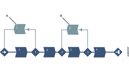
A | Repair path from the first synchronization point to the start of the program. |
B | Repair path from the third synchronization point to the second synchronization point. |
Tightening Area
The tightening area includes the tightening path, i.e., the steps and synchronization points in the multistep tightening program excluding repair and termination paths.
Terminate Area
The steps in the terminate area shows the terminate path followed if the status at a synchronization point is fatal. After the termination path is done the tightening is ended. A termination path always starts at a synchronization point. Only one termination path can start in each synchronization point.
The number of steps to run in the termination path can be between one and three.
It is always possible to terminate from all synchronization points. If no termination path is defined, the program will go directly to the end without running any other steps.
Example: Termination path
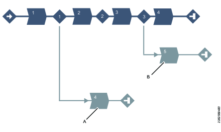
A | Termination path from the first synchronization point to the end of the program. |
B | Termination path from the third synchronization point to the end of the program. |
Configuration
Select on the step, restriction or monitor and click on Configuration at the bottom of the screen to open the Configuration field. To select multiple steps, use Ctrl.
The Configuration field contains different parameters for the steps, monitors and restrictions based on which step, monitor or restriction is selected in the repair area.
Enter the required parameters.
To delete a monitor or restriction, select Delete which is present in that field.
Tool Box
The Tool box includes:
Steps
Monitors
Restrictions
Drag and drop area shortcut keys
Shortcut key | Description |
|---|---|
Space bar + cursor | Move Drag and drop area. |
Drag and drop area functions
Function | Description | |
|---|---|---|
|
|
|
Add step |  | Grab a step in the Tool box. Drag the step to the desired position. Possible positions are indicated by a light blue indication arrow. |
___________ | __________________________ | _________________ |
Mark a step |  | Click on a step to mark it. |
___________ | __________________________ | _________________ |
Move a step |  | To move a step, click on the step and hold the button pressed while moving. |
___________ | __________________________ | _________________ |
Copy step | 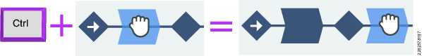 | To copy a step, click the Ctrl button and drag and drop the step. |
___________ | __________________________ | _________________ |
Add repair path |  | Place the step above the synchronization point from where the repair part should start. |
___________ | __________________________ | _________________ |
Add repair step | 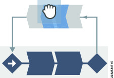 OR 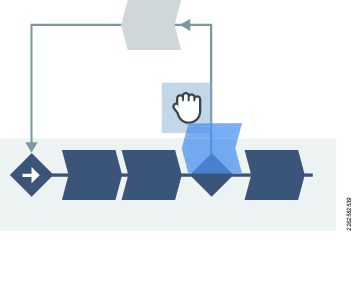 | Place a step in the Repair area to add a repair step. Possible positions are indicated by a light blue indication arrow. or Place the step above the synchronization point from where the repair part starts. The step is then placed before the first step in the repair path. |
___________ | __________________________ | _________________ |
Add terminate path |  | Place the step below the synchronization point from where the termination part should start. |
___________ | __________________________ | _________________ |
Add terminate step |  OR 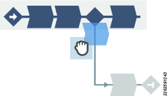 | Place a step in the Terminate area to add a terminate step. Possible positions are indicated by a light blue indication arrow. or Place the step below the synchronization point from where the termination part starts. The step is then placed before the first step in the termination path. |
___________ | __________________________ | _________________ |
Move endpoint for repair path. |  | Click the small arrow to move the endpoint of the repair path. |
___________ | __________________________ | _________________ |
Add restriction and monitor |  | Grab a restriction or a monitor in the Tool box. Drag the restriction or monitor to desired step. Possible steps to add a restriction or monitor to, are indicated by changing to a lighter blue color. |
___________ | __________________________ | _________________ |
Forbidden placement |  | A red arrow indicates that it is not possible to place a step. |
|
|
Tightening Steps
This section lists the tightening steps that are valid for the PF6000 and PF6 StepSync Controllers.
General Parameters
Name
It is possible to rename each step, if needed.
Rotational direction
Each of the tightening steps can run either forward, that is to make a tightening, or reverse, to loosen the screw slightly. The arrows indicate this direction. Many of the tightening steps have a direction hard-coded to forward, for example Tighten to Angle, or Tighten to Torque. Steps such as Loosen to Angle or Loosen to Torque have their direction automatically set to reverse.
Step category
For each step, there is an option to choose a step category. By selecting step category, the NOK tightenings will be listed in the event result view with related detailed status together with the corresponding multistep error information. If no selection is made, the detailed status will be set to "uncategorized multistep error". The related detailed status can be customized.
Angle window
A joint is considered Hard if the screw is tightened to its full torque and it rotates 30 degrees (or less) after it has been tightened to its snug point. A Soft joint rotates 720 degrees or more after it has been tightened to its snug point. The hardness parameter defines the Angle Window for the gradient calculation. The harder the joint - the smaller the angle window.
Speed Ramp / Acceleration
For most of the steps it is possible to specify how the acceleration to the target speed should be achieved. Three different settings are possible; Hard, Soft and Manual. The acceleration defined will be used whenever a step is started. Regardless whether the tool is already running with speed at the beginning of the step, the ramp will be used to accelerate to the target speed of the step. This will be the case even if the speed at the start of the step is higher, or lower than the target speed.
Speed ramp - Hard and Soft mode:
Acceleration | Speed ramp used |
|---|---|
Hard | 2000 rpm/s (Speed Ramp between 1000 and 10000 rpm/s is a Hard acceleration.) |
Soft | 500 rpm/s (Speed Ramp between 200 and 1000 rpm/s is a Soft acceleration.) |
Speed ramp - Manual mode:
Parameter | Default value | Minimum limit | Maximum limit |
|---|---|---|---|
Speed | 60 rpm | Must be > 0 | Must be <= Tool Max Speed |
Acceleration | 500 rpm/s | Must be > 0 | Must be <= Tool Max Acceleration |
Using speed shifts (Only available for the PF6 FlexSystem and PF6 StepSync Controllers)
You can define 1-5 angle triggers or torque triggers during a step, where the speed will shift.
Within one step, all the speed shift triggers are based on the same property, that is either torque or angle. They cannot be mixed within one step.
To add a speed shift:
In the Configuration area of a step that can have speed shifts, click Add speed shift and choose an angle range or a torque range. The Speed Shift Angle/Torque fields open.
Add values according to the table below.
Parameter | Description |
|---|---|
Angle/Torque trigger | Must be > 0. |
Speed | Must be > 0. |
Speed ramp type | Hard or soft. |
The Torque triggers and Angle triggers must be less than the step target, depending on the type of the step and the trigger type.
The Torque trigger and Torque speed also validate against the Max torque and Max speed of the tool. A warning or error indicator occurs whenever the Speed Shift settings exceed either the tool max values, or step max values.
It is possible to push the settings to the controller when a tightening program has a warning, but not when a tightening program has an error (fault) indicator.
Controlling braking behavior (Ergo stop/Inertia)
The braking behavior of a Multistep tightening program can be controlled at two possible locations in the program: in a step preceding a reversal of direction of the tightening, and/or at the final step of the tightening program. At other locations in the Multistep program, the braking parameters will not be available in the step's general settings. Braking can be set to either Ergo stop or Inertia. Inertia will brake the tool completely, while Ergo stop will allow for a more ergonomic slowing down of the tightening.
To set the type of braking, go into the settings for the step, and set the Brake configuration dropdown to Ergo stop or Inertia. Inertia has no additional parameters.
Ergo stop parameters
Parameter | Description |
|---|---|
Adaptive brake | Set the Adaptive Brake to On or Off |
Ramp time | Only available when Adaptive Brake is set to Off. Insert time in ms. |
List of individual steps
C - Clutch
This step will run the tool with the programmed Speed in forward direction until the Clutch has been released. When the tool has reported the release of the Clutch the step will finish with OK status.
A tightening program using the Clutch step cannot have any other step assigned.
This step is only valid for the Clutch tools BCV-RE and BCP-RE.
Parameter | Description |
|---|---|
Speed Control | One Speed or Two Speed |
Final Speed | Sets the final speed of the program [rpm] |
Speed Ramp | Switch where speed ramp can be chosen [Hard, Soft] |
Rehit | Rehit detection set to On or Off |
Rehit angle | Sets the rehit angle [°] |
CL - Clutch Loosening
This step will run the tool with the programmed speed in reverse direction until the tool trigger is released.
A loosening program using the Clutch step can't have any other step assigned.
This step is only valid for the Clutch tools BCV-RE and BCP-RE.
Parameter | Description |
|---|---|
Final | Sets the speed of the program [rpm] |
W – Wait
In this step the tool waits the specified amount of time. The tool does not rotate while waiting.
The tool waits the specified time. If the hold position is set to On the tool holds the position during the Wait time.
SR - Socket Release
This step runs the tool with speed n in the backward direction until the target angle is reached. The target angle is measured from the start of the step.
This step is only allowed to use as the last step in the tightening path of a multistep tightening program. However, it is possible to add a sync point after this step.
Parameter | Description |
|---|---|
Target angle | The angle target. Default: 3º , must be > 0 |
Speed ramp type | Hard, soft, or manual. Default: Hard. If you select Manual, the Speed ramp field opens. |
Speed ramp | If Speed ramp type is Manual, this field opens. Default: 500 rpm/s. |
Speed | Default: 60 rpm. |
DI – Run Until Digital Input
This steps runs the tool, in the direction defined by parameter Direction, until the input specified by Digital Input goes high or low depending on the value of Stop Condition.
This step is not available for STB tools.
Parameter | Description |
|---|---|
Direction | Forward, or Backward |
Digital Input | One of the following local digital inputs on the controller can be selected:
|
Brake (Only valid for PF6 Flex and PF6 Stepsync controllers). | If On the tool will be stopped when the target is reached. If Off the program goes directly to the next step without stopping the tool. |
Stop Condition |
|
Speed (rpm) | Default: 60 rpm. |
Speed ramp type | Hard, soft, or manual. Default: Hard. If you select Manual, the Speed ramp field opens. |
Speed ramp | Available if Speed ramp type is Manual. Default: 500 rpm/s. |
A – Tighten to Angle / Loosen to Angle
A – Tighten to Angle
This step runs the tool until the target angle is reached. The target angle is measured from the start of the step.
A – Loosen to Angle
This step runs the tool with the speed n in the backward direction until the angle target is reached. The target angle is measured from the start of the step.
Parameters
Parameter | Description |
|---|---|
Target angle | The angle target. Must be > 0. |
Speed | Default: 60 rpm. |
Speed ramp type | Hard, soft, or manual. Default: Hard. If you select Manual, the Speed ramp field opens. |
Speed ramp | If Speed ramp type is Manual, this field opens. Default: 500 rpm/s. |
Brake (Only valid for PF6 Flex and PF6 Stepsync controllers). | If On the tool will be stopped when the target is reached. If Off the program goes directly to the next step without stopping the tool. |
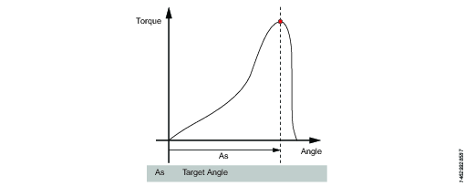
TrR – Loosen to Trigger Release
This step is valid only for the PF6000 controller.
This step runs in the backward direction until the tool trigger is released (loosen). It can only be used as a last step in a program.
For STB tools, this step is only applicable for loosening programs.
Parameter | Description |
|---|---|
Speed | Numerical value for rotation speed; in rpm. |
Speed Ramp Type | List of options where speed ramp can be chosen [Hard, Soft, Manual] |
TTTR – Tighten to Trigger Release
This step runs until the tool trigger is released (tighten). It can only be used as a last step in a tightening program.
Parameter | Description |
|---|---|
Speed | Numerical value for rotation speed; in rpm. |
Speed Ramp Type | List of options where speed ramp can be chosen [Hard, Soft, Manual] |
Tighten to yield, method 2 (YM2)
This step is valid only for the PF6 Stepsync controller and not valid for PF6000 controller.
This step runs the tool with the specified speed in the forward direction until the yield point is detected.
Search for the yield point starts when the torque has reached Tt. The average of the torque over Af degrees is calculated. This procedure is repeated N rs times.
A reference slope is calculated with linear regression over the N rs points. After that, new average values are continuously calculated over A f degrees.
The actual slope is calculated with linear regression over the last N s average points. The yield point is reached when the slope is less than Py % of the reference slope.
Parameter | Description |
|---|---|
Target torque | Must be > 0. |
Filter angle | Default: 1. Must be > 0. |
Number of samples | Default: 6. Must be >=4. |
Number pf samples, reference | Default: 6. Must be >=4. |
Yield point percentage | Default: 90%. Must be >20%. |
Speed | Default: 60 rpm. Must be > 0. |
Speed ramp type | Hard, soft, or manual. Default: Hard. If you select Manual, the Speed ramp field opens. |
Speed ramp | If Speed ramp type is Manual, this field opens. Default: 500 rpm/s. |
Brake (Only valid for PF6 Flex and PF6 Stepsync controllers). | If On the tool will be stopped when the target is reached. If Off the program goes directly to the next step without stopping the tool. |
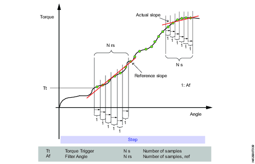
T - Tighten to Torque / Loosen to Torque
T – Tighten to Torque
This step runs the tool with the programmed speed in forward direction until the target torque is reached.
Parameter | Description |
|---|---|
Target torque | The torque target. Must be > 0. |
Speed ramp type | Hard, soft, or manual. Default: Hard. If you select Manual, the Speed ramp field opens. |
Speed | Default: 60 rpm. Must be > 0. |
Speed ramp | If Speed ramp type is Manual, this field opens. Default: 500 rpm/s. |
Brake (Only valid for PF6 Flex and PF6 Stepsync controllers). | If On the tool will be stopped when the target is reached. If Off the program goes directly to the next step without stopping the tool. |
T – Loosen to Torque
This step runs the tool with the speed in the backward direction. For the step to be active, the torque must first exceed 110 % of the Target torque. The Target torque should be set to a positive value. After reaching the target torque, the step runs until the torque drops below the target torque.
Parameter | Description |
|---|---|
Target torque | The torque target. Must be > 0. |
Speed ramp type | Hard, soft, or manual. Default: Hard. If you select Manual, the Speed ramp field opens. |
Speed | Default: 60 rpm. Must be > 0. |
Speed ramp | If Speed ramp type is Manual, this field opens. Default: 500 rpm/s. |
Brake (Only valid for PF6 Flex and PF6 Stepsync controllers). | If On the tool will be stopped when the target is reached. If Off the program goes directly to the next step without stopping the tool. |
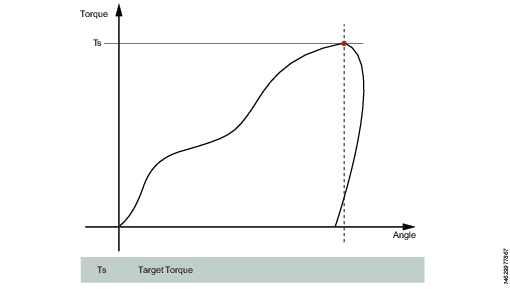
T+A – Tighten to Torque Plus Angle
This step runs the tool until the target torque is reached. From this point it continues to run an additional target angle.
Parameter | Description |
|---|---|
Target torque | The torque target. Must be > 0. |
Target angle | The angle target. Must be > 0. |
Speed ramp type | Hard, soft, or manual. Default: Hard. If you select Manual, the Speed ramp field opens. |
Speed ramp | If Speed ramp type is Manual, this field opens. Default: 500 rpm/s. |
Speed | Default: 60 rpm. |
Brake (Only valid for PF6 Flex and PF6 Stepsync controllers). | If On the tool will be stopped when the target is reached. If Off the program goes directly to the next step without stopping the tool. |
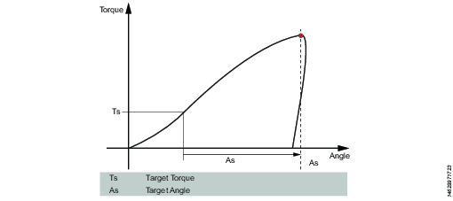
T|A – Tighten to Torque or Angle
This step runs the tool with the speed n in the forward direction until the first of either torque target or angle target is reached. The torque and angle measurements start at the beginning of the step.
Parameter | Description |
|---|---|
Target torque | Must be > 0. |
Target angle | Must be > 0. |
Speed | Default: 60 rpm. Must be > 0. |
Speed ramp type | Hard, soft, or manual. Default: Hard. If you select Manual, the Speed ramp field opens. |
Speed ramp | If Speed ramp type is Manual, this field opens. Default: 500 rpm/s. |
Brake (Only valid for PF6 Flex and PF6 Stepsync controllers). | If On the tool will be stopped when the target is reached. If Off the program goes directly to the next step without stopping the tool. |
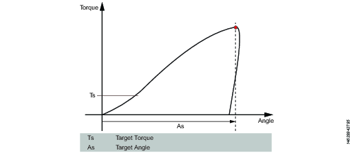
T&A – Tighten to Torque and Angle
The tool runs until with the specified speed in the forward direction until both target torque and target angle are reached. The target torque and the target angle must be set to > 0.
Parameter | Description |
|---|---|
Target torque | Must be > 0. |
Target angle | Default: 0. Must be > 0. |
Speed | Default: 60 rpm. Must be > 0. |
Speed ramp type | Hard, soft, or manual. Default: Hard. If you select Manual, the Speed ramp field opens. |
Brake (Only valid for PF6 Flex and PF6 Stepsync controllers). | If On the tool will be stopped when the target is reached. If Off the program goes directly to the next step without stopping the tool. |
DT – Tighten to DynaTork
This step runs the tool with speed n in the forward direction until the Target torque is reached. The tool will then hold the current constant at the DynaTork Percentage of Target torque during the DynaTork time.
To avoid overheating of the tool, it is strongly recommended to never run DynaTork to more than 40% of the maximum torque of the tool.
Parameter | Description |
|---|---|
Target torque | The torque target. Must be > 0. |
DynaTork Time | The time DynaTork will be active. |
DynaTork Percentage | The percentage of Torque target. |
Speed ramp type | Hard, soft, or manual. Default: Hard. If you select Manual, the Speed ramp field opens. |
Speed ramp | If Speed ramp type is Manual, this field opens. Default: 500 rpm/s. |
Speed (rpm) | Default: 60 rpm. |
Brake (Only valid for PF6 Flex and PF6 Stepsync controllers). | If On the tool will be stopped when the target is reached. If Off the program goes directly to the next step without stopping the tool. |
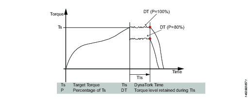
Y – Tighten to Yield
This step is not available for STB tools.
This strategy runs the tool with the speed in the forward direction until the yield point is detected. The yield point is found by monitoring the torque gradient from the point where the torque goes above the Trigger Torque level, calculated based on Torque and Angle distance measurements. The Angle distance parameter is set according to the specified hardness of the joint.
Set the Gradient angle window (for hard joint, for soft joint or for manually setting of the Angle window). If Manual is selected, the Angle Window must be set. A joint is considered Hard if the screw is tightened to its full torque and it rotates 30 degrees or less after it has been tightened to its snug point. A Soft joint rotates 720 degrees or more after it has been tightened to its snug point. The hardness parameter defines the Angle Window for the gradient calculation. The harder the joint - the smaller the angle window.
Parameter | Description |
|---|---|
Gradient Angle Window | Specifies Angle Window:
|
Angle Window | Available when Gradient Angle Window is set to Manual. Must be > 0 and <= 100. |
Trigger Torque | The angle measurement starts at this trigger. Must be >= 0 and < Tool MaxTorque. |
Damping | Frequency in which the gradient is being calculated. Must be > 0 and < 100 and < Angle window. |
Yield Point Percentage | Must be >= 20 % |
Speed | Default: 60 rpm. Must be > 0. |
Speed ramp type | Hard, soft, or manual. Default: Hard. If you select Manual, the Speed ramp field opens. |
Torque Filter Type | The type of the filter:
|
Cut-off Frequency | Needs to be specified when Torque Filter Type is set to Low pass:
|
Number of Samples | Needs to be specified when Torque Filter Type is set to Sliding Average:
|
Brake (Only valid for PF6 Flex and PF6 Stepsync controllers). | If On the tool will be stopped when the target is reached. If Off the program goes directly to the next step without stopping the tool. |
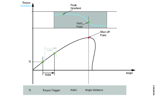
ThCT – Thread Cutting to Torque
The Thread Cutting to Torque function enables tightening where the Rundown torque required is greater than the Rundown complete torque, for example when tightening thin layers of metal using self-threading (or selftapping) screws. The tool runs in forward direction until the Thread Cutting Angle (Aw) is reached. The thread cutting angle window is measured from when the torque passes Thread Cut Trigger Torque (Ttc) for the first time. From the point where Thread cutting angle is reached, the step continues to run until the Target Torque (Tt) is reached.
Parameter | Description |
|---|---|
Target torque | Must be > 0. |
Thread Cutting Angle Window | Default: 0. Must be > 0. |
Trigger Torque | The angle measurement starts at this trigger. |
Speed | Default: 60 rpm. Must be > 0. |
Speed ramp type | Hard, soft, or manual. Default: Hard. If you select Manual, the Speed ramp field opens. |
Brake (Only valid for PF6 Flex and PF6 Stepsync controllers). | If On the tool will be stopped when the target is reached. If Off the program goes directly to the next step without stopping the tool. |
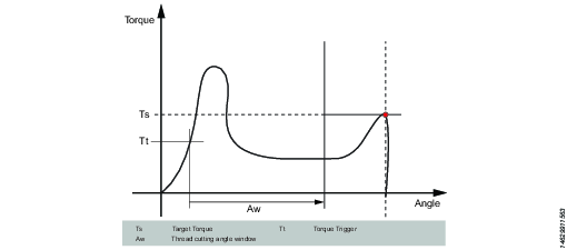
RD – Rundown
This step is not available for STB tools.
Rundown step is the part of the tightening from when the screw enters the thread until just before the screw head touches the underlying surface and snug point is reached. The torque required during rundown does not contribute to any clamping force.
This step runs the tool with the speed in the forward direction, and depending on the Rundown Type, Torque or Snug the step behavior is as follows:
Rundown Type: To Torque: The step stops when the specified target torque is found.
Rundown Type: To Snug: The snug gradient calculation starts at the specified torque trigger level Tt. If no torque trigger is set the gradient calculation is started at the start of the step.
The slope calculation is made between two angle points Ad degrees apart and is calculated as: (Tn – Tn-1) / (An – An-1) and as soon as two slopes after each other are larger than TSLOPE the snug point is found.
Parameter | Description |
|---|---|
Rundown type | To Torque or To Snug. |
Target torque | Default: "not set". Must be > 0. |
Speed | Default: 60 rpm. Must be > 0. |
Speed ramp type | Hard, soft, or manual. Default: Hard. If you select Manual, the Speed ramp field opens. |
Speed ramp | If Speed ramp type is Manual, this field opens. Default: 500 rpm/s. |
Trigger Torque | If Rundown type is To Snug, the Trigger torque field is displayed. Default: "not set". Must be > 0. |
Delta Angle | If Rundown type is To Snug, the Delta angle field is displayed. Default: "0". Must be > 0. |
Torque Rate | If Rundown type is To Snug, the Torque rate field is displayed. Default: "0". Must be > 0. |
Brake (Only valid for PF6 Flex and PF6 Stepsync controllers). | If On the tool will be stopped when the target is reached. If Off the program goes directly to the next step without stopping the tool. |

Engage (E)
This step is not available for STB tools.
This step runs the tool in both directions until the socket engages the screw. The step continues until Target torque or Target angle is reached, provided that Continue if not Engaged is set to Yes. If Target Angle is reached in any direction, the direction is reversed. Limit the search iterations by entering Max Engage Attempts. If Target Torque is reached in any direction the step will finish with OK status.
Ext - External Result
External result is a strategy used when an OK tightening is indicated by an external digital signal (and not by torque or angle values measured during tightening). This external signal can be provided through any means that can provide a digital signal into the Power Focus 6000 (e.g through the I/O bus).
When the signal is sent, the result view (logged data) will show the value of the Target parameter provided in the tightening program (specified torque value, angle value, or text string). These (torque and angle) values do not represent actual measured values, but only inserted text.
Parameter | Description |
|---|---|
Torque <Target torque> | Numerical value for desired displayed target torque value. A signal could for example come from a Click Wrench and display <Target torque>. |
Angle <Target angle> | Numerical value for desired displayed target angle value. A signal could for example come from a Click Wrench and display <Target angle>. |
Text | Alphanumerical string for desired displayed text. For example: "Oil has been changed". |
MWR - Mechatronic Wrench
Mechatronic Wrench is a specialized step that can be used only in conjunction with the Mechatronic Wrench (MWR).
This step cannot be used in combination with other steps. No restrictions can be used with this step. By default, the step has three monitors: Peak Torque, Angle, and Click.
Parameter | Description |
|---|---|
Loosening limit | Numerical value for negative torque (i.e. torque in the loosening direction) at which point the tightening result is marked as NOK (False direction of tightening (loosen)); in Nm. |
Tool Size | Numerical value for the specific length of the end fitting tool installed on the MWR-TA; in mm. |
Tool Bend | Numerical value for the end fitting tool installed on the MWR-TA; in °/Nm. |
Rehit Angle Window | Numerical value for the angle for determining if the screw was already tightened if the torque is reached; in °. |
Max Angular Rate | Numerical value for the max rate at which the screw can be tightened; in °/s. |
WP - Wrench Production
Strategy used for the quality test of the tightening performed with an STwrench.
Parameter | Description |
|---|---|
Control Strategy | The Wrench Production step type can be configured with the following control strategies.
|
Based on the control strategy selected, a combination of some of the parameters listed below will be displayed.
Parameters | Description |
|---|---|
Target Torque | Defines the target torque for tightening step. |
Measure torque at | Specifies where the torque will be measured. Choose between Peak torque or Peak angle.
|
Angle search limit | This is an offset that is used to the set the torque result value for a tightening. Measure torque at must be set to Peak Angle for this parameter to be available. |
Ratchet time | Numerical value for ratchet time which is by default 5000 ms. This allows the operator to release the torque for a while and recharge during the tightening operation. If the Ratchet time is exceeded the result of the tightening is marked as NOK with the reason "Tightening timeout". |
End cycle time | Numerical value in ms to indicate the end cycle time. Applied when torque goes below the rundown complete |
Torque correction coefficient | The parameter is used to correct the torque reading when using an extension or torque multiplier on the wrench. Default value is 1. |
Angle correction | The parameter is used to correct the angle reading when using an extension or torque multiplier on the wrench. Default value is 0. |
Target Angle | Defines the target angle for tightening step. |
Rehit detection | On or Off. Rehit detection can be used to determine when a tightening is a rehit based on the angle limit setting. Angle limit for rehit is enabled if Rehit direction is set to On. |
Linear slope coefficient | Linear slope coefficient characterizes the joint stiffness in the linear part of the curve, as torque/angle slope in the Nm/Deg measurement unit. |
Compensate value | Choose between Average torque and Peak torque. The Compensate value specifies how the PVT will be calculated. Average torque - The PVT will be based on an average calculated using the following:
Peak torque - The PVT will be based on the peak value measured before snug was detected. |
Delay monitoring | PVT calculation will not start before this window has been passed, starts at tightening start. |
PVT interval | Sets how many degrees the PVT window shall be calculated for, start from the PVT distance point. |
PVT distance | Sets how many degrees prior to snug the system shall start the PVT window. |
Prevailing torque min | Prevailing torque minimum limit. |
Prevailing torque max | Prevailing torque maximum limit |
WQ - Wrench Quality
Strategy used for quality test of tightenings with an STwrench.
Parameter | Description |
|---|---|
Control Strategy | The Wrench Quality strategy can be configured with the following control strategies.
|
Based on the control strategy selected, a combination of some of the parameters listed below will be displayed.
Parameters | Description |
|---|---|
Ratchet time | Numerical value for ratchet time which is by default 5000 ms. This allows the operator to release the torque for a while and recharge during the tightening operation. If the Ratchet time is exceeded the result of the tightening is marked as NOK with the reason "Tightening timeout". |
Torque correction coefficient | The parameter is used to correct the torque reading when using an extension or torque multiplier on the wrench. Default value is 1. |
Angle correction | The parameter is used to correct the angle reading when using an extension or torque multiplier on the wrench. Default value is 0. |
Target Angle | Defines the target angle for tightening step. |
Rehit detection | On or Off. Rehit detection can be used to determine when a tightening is a rehit based on the angle limit setting. Angle limit for rehit is enabled if Rehit direction is set to On. |
Linear slope coefficient | Linear slope coefficient characterizes the joint stiffness in the linear part of the curve, as torque/angle slope in the Nm/Deg measurement unit. |
Step Monitors
The step monitors are used to verify that the tightening was achieved according to the specification, for example, angle limits or torque. Each step has mandatory step monitors and optional step monitors. The mandatory monitors are included when dragging a new step to the multistep program. The optional monitors are flexible and can be placed as needed in the multistep program. Every step can have up to eight monitors each.
The following monitors are automatically added to every step that is added to the multistep tightening program.
Step Monitor | Applicable steps |
|---|---|
Angle | All |
Peak Torque | All |
A – Angle
This step monitor measures the maximum angle reached during the monitor and checks that it is between High limit and Low limit. The angle measurement starts at the start of the monitor or, if specified, at the point where the torque passes Trigger torque for the first time during the monitor.
Parameter | Description |
|---|---|
Type | Four angle types are available: Peak angle (default), Angle at peak torque, Shut off angle, and Angle at end. |
Trigger torque | The angle measurement starts at this trigger. |
Low Limit | Lowest acceptable angle. |
High Limit | Highest acceptable angle. |
YA – Angle from Yield
This monitor measures the peak angle reached from the yield point and checks that the peak angle is within the limit.
This step monitor is not available for the STB tools.
Parameter | Description |
|---|---|
Gradient Angle Window | Specifies Angle Window:
|
Angle Window | Available when Gradient Angle Window is set to Manual. Must be > 0 and <= 100. |
Yield Point Percentage | Must be >= 20 % |
Trigger Torque | The angle measurement starts at this trigger. Must be > 0 and < Tool MaxTorque. |
Damping | Frequency in which the gradient is being calculated. Must be > 0 and < 100 and < Angle window. |
Low Limit | Lowest acceptable angle. Must be >= 0 |
High Limit | Highest acceptable angle. Must be > 0 |
Torque Filter Type | The type of the filter:
|
Cut-off Frequency | Needs to be specified when Torque Filter Type is set to Low pass:
|
Number of Samples | Needs to be specified when Torque Filter Type is set to Sliding Average:
|
MT – Mean Torque
This monitor measures the average torque during the monitor and checks the calculated value is within the limits.
This step monitor is not available for the STB tools.
Parameter | Description |
|---|---|
Type | Specifies start condition:
|
Torque Trigger | Available when Type is set to Trigger Torque, Angle Trigger or Angle Window. Must be >= 0 and < Tool Max Torque. |
Angle Trigger | Available when Type is set to Angle Trigger or Angle Window. Must be > 0. |
Angle Window | Available when Type is set to Angle Window. Must be > 0.
|
Time Interval | Available when Type is set to Time Interval. Must be > 0. |
Low Limit | Lowest acceptable torque. |
High Limit | Highest acceptable torque. |
PT – Peak Torque
This step monitor measures the maximum torque reached during the monitor, including any over shoot, and checks that it is between High limit and Low limit.
Parameter | Description |
|---|---|
Low Limit | Lowest acceptable torque. |
High Limit | Highest acceptable torque. |
PTCA – Post Thread Cut Angle
Measures the angle achieved during the monitoring and checks that it is between the specified angle limits. The Trigger Torque level is ignored until the end of the Thread cut angle window is reached. After that, the angle measuring starts as soon as the measured torque is above Trigger Torque. The parameter Stop Condition specifies where the angle measurement should end.
Parameter | Description |
|---|---|
Trigger torque | Must be >= 0 |
Thread cutting angle window | Must be > 0 |
Angle measurement type | Peak angle Angle at peak torque Shut off angle Angle at end |
Thread cut trigger torque | Must be >= 0 |
Low Limit | Must be >= 0 |
High Limit | Must be > 0 Must be > Low limit |
PTCPT – Post Thread Cut Peak Torque
Measures the maximum torque achieved during the monitoring, including any over-shoot, and checks that it is between the Torque limits. All torque values are ignored until the end of the Thread cut angle window has been reached.
Parameter | Description |
|---|---|
Thread cut trigger torque | Must be >= 0 |
Thread cutting angle window | Must be > 0 |
Low Limit | Must be >= 0 |
High Limit | Must be > 0 Must be > Low limit |
PVTH – Post View Torque High
This monitor checks that all torque values in the angle window are below the limit.
All torque values in the Angle Window Length should be below the High limit. The Angle Window starts at the angle degrees set in Start Angle in reverse direction from the shut-off point. This then spans for the angle degrees set in Angle Window Length in reverse direction. If Start Angle is left blank the Angle Window starts at the shut-off point. The torque values used in the monitor are based on the mean torque value, calculated over Number of Samples. If the total angle of the step is less than Start Angle plus Angle Window Length the monitor will report NOK.
Parameter | Description |
|---|---|
Start Angle | Must be >= 0 |
Window length | Must be <= 0 |
Number of samples | 1 |
High Limit | Highest acceptable torque. |
PVTL – Post View Torque Low
Same as monitor Post View Torque High but this monitor checks that all torque values in the Angle Window Length are above Low Limit instead.
Parameter | Description |
|---|---|
Start Angle | Must be >= 0 |
Window length | Must be <= 0 |
Number of samples | 1 |
Low Limit | Lowest acceptable torque. |
PrT – Prevailing Torque
The monitor calculates the prevailing torque value in the Window Length and checks that it is between the Torque limits. The Angle Window starts at the angle degrees set in Start Angle in reverse direction from the shut-off point. This then spans for the angle degrees set in Angle Window Length in reverse direction. If Start Angle is left blank the angle window starts at the shut-off point. The calculated prevailing torque value is the mean or peak torque value (depending on the parameter set by the user) during the Window Length. The calculated value is saved as result data Prevailing Torque Measured. If Torque compensation is set to On, the Prevailing Torque Measured will be subtracted from all torque result values in consecutive steps. Any previously calculated prevailing torque compensation values will no longer be subtracted from torque result values. If Torque compensation is set to No, no subtraction will be made in consecutive steps.
If the total angle of the step is less than the Start Angle plus Window Length, then the monitor will report NOK.
Prevailing torque can be measured as an average of measured values, or at peak torque. To choose between these two modes, set the Use Value parameter to either Mean torque (for average values), or Peak torque (for peak value).
Parameter | Description |
|---|---|
Torque Compensation | On or off. |
Start Angle | Must be > 0 |
Window length | Must be >= 0 |
Low Limit | Must be > 0 |
High Limit | Must be >= 0 |
Use value | Mean torque (for average values), or Peak torque (for peak value). |
SOT – Shut Off Torque
The shut off point is the point where the step reaches its target. The torque is measured at the shut off point and checked to be between High limit and Low limit.
Parameter | Description |
|---|---|
Low Limit | Lowest acceptable torque. |
High Limit | Highest acceptable torque. |
SOC – Shut Off Current
The shut off point is the point where the step reaches its target. The current is measured at the shut off point and checked to be between High limit and Low limit .
Parameter | Description |
|---|---|
Low Limit | Lowest acceptable current. |
High Limit | Highest acceptable current. |
SSD - Stick Slip Detection
This step monitor detects and reports stick slip effects during a step. The detection is done by counting the number of times the torque falls below the Trigger Level. If the number of times is larger than Maximum Number of Oscillations then the stick slip error is reported. The monitor operates in two different modes, Dynamic or Fixed. The difference between the modes is the way that the Trigger level is calculated.
Dynamic Torque: Trigger Level is dynamically calculated as Peak Torque Percentage of the current max torque, which has been achieved so far during the monitoring. The monitoring is started as soon as the torque passes the Trigger Torque.
Fixed Torque: Trigger Level is the fixed Trigger Torque specified by the user. In this mode the percentage is not needed.
If the torque never reaches the Trigger Torque then the monitoring is not started, this will result in status NOK.
Parameter | Description |
|---|---|
Type | Specifies what type of Stick slip detection that will be done in the monitor Stick Slip detection. Default: Dynamic torque. |
Peak Torque Percentage | Default: 80%, Must be >=10 and < 100. |
Trigger Torque | Default: 5, Must be >= 0 and < Tool max torque. |
Maximum Number of Oscillations | Default: 5, Must be >= 3 and <20. |
Ti – Time
Measures the elapsed time during the monitor and checks that it is between the time limits. The time measurement starts at the start of the monitor and, if the Trigger Torque is specified, at the point where the torque passes Trigger Torque for the first time during the monitor.
Parameter | Description |
|---|---|
Trigger Torque | Must be >= 0 and < Tool max torque. |
Low Limit | Must be >= 0 |
High Limit | Must be > 0 Must be > Low limit |
TG – Torque Gradient
This monitor checks the gradient is within the limit.
Parameter | Description |
|---|---|
Gradient Angle Window | Specifies Angle Window:
|
Angle Window | Available when Gradient Angle Window is set to Manual. Must be > 0 and <= 100. |
End Point Check | If set to Yes, only the gradient measured at the shut off point of the step is checked to be within the limits. |
Trigger Torque | The angle measurement starts at this trigger. Must be > 0 and < Tool MaxTorque. |
Damping | Frequency in which the gradient is being calculated. Must be > 0 and < 100 and < Angle window. |
Low Limit | Lowest acceptable torque gradient. Must be >= -100. |
High Limit | Highest acceptable torque gradient. Must be > -100 and > Low limit. |
Torque Filter Type | The type of the filter:
|
Cut-off Frequency | Needs to be specified when Torque Filter Type is set to Low pass:
|
Number of Samples | Needs to be specified when Torque Filter Type is set to Sliding Average:
|
Angle Offset | Available when End Point Check is set to No. Specifies the degrees that the calculation of the gradient start after the trigger torque is passed for the first time. |
TAW – Torque in Angle Window
This monitor checks that all torque values in the angle window are within the torque limits.
Parameter | Description |
|---|---|
Trigger Torque | Must be >= 0 |
Start Angle | Must be > 0 |
Window Length | Must be <= 0 |
Low Limit | Must be >= 0 |
High Limit | Must be > 0 Must be > Low limit |
NOK if window is passed | If set to Yes, status of this monitor is NOK if the end of angle window is not reached. |
TRD – Torque Rate and Deviation
This step monitor measures and checks the torque rate, i.e. the ratio of torque vs. angle. The calculated torque rate is checked if it is within the torque rate limits defined by High Limit and Low Limit.
Parameter | Description |
|---|---|
Trigger Torque | Torque of the angle start point. |
Start Point Angle | When Start point angle has been measured from Trigger torque the measuring of the torque starts. |
End Point Angle | Angle point where the measuring of the torque is stopped. |
End Point Torque | Torque where the measuring of the torque is stopped. |
Low Limit | Lowest acceptable torque. |
High Limit | Highest acceptable torque. |
Limit | Must be > 0 |
Cl – Click
Monitor to enable click torque and click angle results. This monitor has no settings, and can only be used in conjunction with the MWR step.
LD - Loosening Detection
This monitor can be used to check the torque and direction to see if a loosening is attempted when using the Wrench Production step strategy for an STWrench. If the applied torque is above the value set for Loosening Limit in the direction opposite to the configured thread direction of the program, the result shall be reported as NOK.
Step Restrictions
The following sections describe the step restrictions available for the PowerFocus 6000 Controller and the PowerFocus 6000 StepSync controller.
In the The PowerFocus 6000 StepSync controller, it is possible to use syncronization points in the tightening program and when any condition that is set for a restriction is met, the tool will be stopped immediately and the program jumps to the next synchronization point (only valid for the Power Focus 6000 StepSync and PF6 Flex System controllers), or the end of the program. Whereas for a PowerFocus 6000 controller, the tool is stopped immediately and the program jumps to the end of the program.
To make sure the tightening stops if something unexpected happens, it is possible to add restrictions to the multistep tightening program. For each restriction, select Repairable = Yes to allow retry when tightening stops. For each of the steps in a multistep program it is possible to have up to four restrictions.
The following restrictions are automatically added to every step that is added to the multistep tightening program.
Step Restriction | Applicable steps |
|---|---|
Step Restriction Maximum Time | All except External Result and MWR |
Step Restriction Maximum Torque |
|
Step Restriction Maximum Angle |
|
CTh – Cross Thread
This restriction checks the angle from the point where torque passes Start torque (T1) to the point where the torque passes End torque (T2). If the angle measured from Start torque (T1) is higher than Maximum limit (Amax), the tool is stopped immediately.
When the torque passes End torque (T2), the measured angle is checked against the limit Minimum limit (Amin). If the angle is lower than this limit, the tool is stopped immediately.
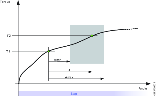
Parameter | Description | In illustration |
|---|---|---|
Start Torque | Must be <=0. | T1 |
End Torque | Must be <=0. | T2 |
Minimum Limit | The low angle limit. | Amin |
Maximum Limit | The high angle limit. | Amax |
A – Maximum Angle
This restriction measures the angle. If the measured angle reaches the Maximum Limit, the tool is stopped immediately. The angle is measured from the start of the restriction or, if specified, from the point where the torque passes Trigger Torque for the first time during the restriction.
Parameter | Description |
|---|---|
Trigger Torque | If specified, this is the torque from where the angle is measured. |
Maximum Limit | If this limit is reached the tool is stopped immediately. |
T – Maximum Torque
This restriction checks the torque. If the measured torque exceeds the Maximum limit, the tool is stopped immediately.
Parameter | Description |
|---|---|
Maximum Limit | If the torque reaches this specified limit the tool is stopped immediately. |
Ti – Maximum Time
This restriction checks the time. If Maximum Limit is reached, the tool is stopped immediately.
Parameter | Description |
|---|---|
Maximum Limit | If this time is elapsed, the tool is stopped immediately. |
RH – Rehit
This restriction checks the torque. If the measured torque exceeds the Detection Torque, the tool is stopped immediately and the program jumps to the end of the program. It is only possible to add step Rehit restriction to the first step of the multistep tightening program. Once the Rehit restriction has been added to the first step it shall not be possible to move the step to any other position within the tightening program. The Rehit restriction has to be deleted from the first step in order to move it to other position in the tightening program.
Parameter | Description |
|---|---|
Detection Torque | If the measured torque exceeds the Detection Torque, the tool is stopped immediately and the program jumps to the end of the program. Must be greater than zero. |
RT – Rescinding Torque
This restriction checks the torque and if the measured torque drops below the condition of the restriction the tool is stopped immediately and the program jumps to end of the program. There are two methods of Rescinding Torque Restrictions for Torque and Angle control processes
Parameter | Description |
|---|---|
Type | Torque control processes or Angle control processes. Torque control processes: Torque control processes checks the torque. If the measured torque drops below the Rescinding Torque Limit the tool is stopped immediately and the program jumps to the end of the program. For the restriction to be active the torque must first exceed 110 % of the Rescinding Torque Limit Angle control processes: This restriction checks the maximum torque reached during the restriction. For the restriction to be active the torque must first exceed the Trigger Torque. If the measured torque drops below the maximum torque for longer time than Rescinding Torque Time the tool is stopped immediately and the program jumps to the end of the program. Cable tools have the option of choosing Rescinding Torque for Angle. This restriction is controlled by two parameters: Peak Torque Percentage and Rescending Torque Time. Percentage sets the downward deviation from the last peak torque, and Rescending Torque Time sets the duration (between 5 and 500 ms) of that deviation. Only when both conditions (equal to or lower than the indicated percentage for the set duration) are met, will the program be interrupted and jump to the end. |
Rescinding Torque Limit | Default: 10 Nm. Must be > 0. |
TG – Torque Gradient
This restriction checks the gradient and if it is outside the limits the tool is stopped immediately and the program jumps to the end of the program.
Parameter | Description |
|---|---|
Gradient Angle Window | Specifies Angle Window:
|
Angle Window | Available when Gradient Angle Window is set to Manual. Must be > 0 and <= 100. |
Trigger Torque | Must be > 0 and < Tool MaxTorque. |
Damping | Frequency in which the gradient is being calculated. Must be > 0 and < 100 and < Angle window. |
Minimum Limit | Must be >= -100. |
Maximum Limit | Must be > -100 and > Low limit. |
Torque Filter Type | The type of the filter:
|
Cut-off Frequency | Needs to be specified when Torque Filter Type is set to Low pass:
|
Number of Samples | Needs to be specified when Torque Filter Type is set to Sliding Average:
|
TAW – Torque in Angle Window
This restriction checks that the measured torque in the Angle Window Length is between the Torque limits. If the measured torque is outside the limits the tool is stopped immediately and the program jumps to the end. The Angle Window Length starts at the Start Angle from the point that the torque first passed the Trigger Torque. If Trigger Torque is not set, then the Start Angle begins at the start of the restriction.
If the end of the Angle Window Length is not reached, the status of the restriction is NOK.
Parameter | Description |
|---|---|
Trigger Torque | Must be >= 0 |
Start Angle | Must be >= 0 |
Window Length | Must be >0 |
Minimum Limit | Must be >= 0 |
Maximum Limit | Must be <= Minimum limit |
TCD - Torque vs Current Deviation
This restriction verifies that all current measurements converted to the corresponding torque are, at most, the Maximum deviation away from the actual torque measured with the torque transducer. The restriction starts when the torque reaches Trigger Torque for the first time during the step and is active until the step reaches its target.
If Trigger Torque is never reached, the monitor will report OK.
Parameter | Description |
|---|---|
Trigger Torque | Must be >= 0 |
Maximum Deviation | Default: 1, Must be > 0 |
Deleting a Multistep Program
For each Multistep program to be deleted, mark the check box in the leftmost column in the workspace area.
Select the Manage command button, then Delete from the drop-down list.
The selected Multistep program(s) are removed and the list is updated.
STB Tools and Multistep
Due to the wireless nature of STB tools, some multistep functions and behaviors may differ. Besides the general limitations listed here, descriptions of multistep functions will be additional information on STB tools where necessary.
Program Validation
All tightening programs will be validated for compatibility with STB tools before the program is downloaded to the tool. If the chosen tightening program is not compatible with the tool, the tool will be locked. When this error occurs, it will trigger event 5030, "Configuration complexity exceeded".
To unlock the tool, reduce the complexity of the tightening program, or choose a different tightening program altogether.
Result Reporters
The result reporters makes it possible to extract specific values of selected producer from the result. The result reporters belong to a step but has to be tied to the monitor/restriction from which they will read the values. Only monitors or restrictions located in the same step as the result reporter can be selected. A result reporter is added to a step using drag and drop (in the same way as monitors and restrictions). Each result reporter is responsible for reporting a specific result value, for example, Rundown Angle, Final Torque, Prevailing Torque.
It is possible to tie a result reporter to:
program monitors
step monitors
step restrictions
Each result reporter defines a final value type:
FA – Final Angle
FC – Final Current
FT – Final Torque
PT – Prevailing Torque
RA – Rundown Angle
ST – Self-tap Torque
General Parameters
Parameter | Description |
|---|---|
Producer | Specifies which monitor/restriction produces the value. |
Value | Specifies which value to show from the selected producer. |
Limitations:
It is only possible to add a result reporter on a monitor/restriction belonging to a step in main path or a program monitor/program restriction.
There may exist several reporters on a step if they are of different type.
There may exist a result reporter of for example type final angle on every step and program monitor angle.
For those monitor/restrictions that have more than one result value it is possible to add more than one result reporter if the result reporters are of different types.
There may not exist several result reporters of the same type on a step or on a program monitor/restriction.
There is only one result reported for each possible final value type.
Rules:
The internal number of a result item has to be the same as for the corresponding result reporter.
The internal number of a monitor/restriction result has to be the same as the internal number of the monitor/restriction in the configuration.
The step results has to be ordered according to the order of execution. The first executed step has to be first.
Possible values reported by a result reporter if present in the monitor/restriction/step:
The monitors/restrictions measured value (as float or integer)
The monitors/restrictions high and low limits
Status
Torque trigger and angle trigger
Angle target and torque target (read from the step)
Possible values for status:
Low
OK
High
Other
NotSet
The target values do not belong to any step monitor so the target values are taken from the step that the monitor belongs to.
Multistep Template
All created templates are visible in the tab Templates, when creating a multistep program. A template can be inserted (drag-and-drop) and act as a base to build the new multistep program on.
A template can only be dragged into the multistep program when steps have not yet been added. After dragging the template to the multistep program, steps may then be added.
The template itself will not be affected when modifying a multistep tightening program since the template is copied, and not linked to the program.
Create multistep program templates in Library > Program templates.
Step Configuration Stages
The controller tightening programs need parameters to be set in order to execute the programs. Selecting a Strategy and either the Target torque or Target angle are mandatory. Other settings are optional. It is also possible to monitor the tightening as it progresses by adding limits within which the torque or angle rotation must remain.
The tightening procedure is divided into four stages: Start, Rundown, Tightening and Stop.
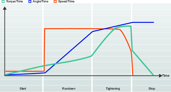
The figure is typical of how tightenings are described. The curves represent how speed, torque and angle vary over time. All tightening strategies are represented in this way. Parameters, monitors and limits are also shown in detailed figures.
A task is defined from the time a trigger is pressed until the tightening target is reached, or an error occurs.
A combination of a tightening strategy together with specific parameter settings forms a tightening program.
The user can create many different tightening programs, and one of them is selected at runtime.
True Angle Compensation
Certain tools can detect and measure the tool rotation during tightening. If the tool is rotated during tightening, the angle measurement may be corrupted. This may lead to a faulty tightening if the tool movement is too great. For variations within specified limits, the controller can compensate these rotations and make a correct tightening.
This is an additional Licensed Feature, available per Virtual Station.
If the tool rotation is outside specified limits during the tightening, the tightening is aborted and NOK is reported. Additional information reports Tool movement exceeded.
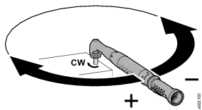
Parameter | Description | Default |
|---|---|---|
Negative angle limit | Defines the maximum negative rotation of the tool. If the value is exceeded the tightening is terminated and an error is reported. This is expressed in a numeric angle value. | Enabled, value set to -30 degree |
Positive angle limit | Defines the maximum positive rotation of the tool. If the value is exceeded the tightening is terminated and an error is reported. This is expressed in a numeric angle value. | Enabled, value set to +30 degree |
STB tools do not have the capability to measure the tool movement. If the True angle compensation is set to On, the error message Invalid Tightening Program will be displayed together with the additional information Feature not supported by the tool.
Current Monitoring
Current monitoring provides extra security to monitor the tightening torque and is a complement to the torque sensor within the tool.
At final target torque, the rotor current is measured and converted to a torque value. If the calculated torque is within 10% of the measured torque, the tightening is considered to be OK.
Parameter | Description | Default |
|---|---|---|
Current monitoring | Switch with On - Off position Off: Current monitoring is disabled and the tool torque is measured by the torque sensor. On: the current is measured at final torque target and converted to a torque value. The calculated torque is compared to the measured torque. If the difference is within 10%, the tightening is considered to be ok. | Off |
Start Stage
The Start stage initiates the tightening, enables socket and thread finding.
Parameter name | Condition | Description |
|---|---|---|
Soft start |
| Enables setting of the tool’s speed, angle and maximum torque to facilitate the threading. Off: Soft start is turned off. On: Soft start is turned on. |
Speed | Soft start = On | Defines the speed during Soft start. |
Angle | Soft start = On | Defines the target angle to turn the spindle for the bolt to enter the thread. |
Torque max | Soft start = On | Defines the upper torque limit during Soft start. If Torque max is exceeded, the tightening is aborted and an error message is shown. The tightening will be considered NOK. |
Positive | True angle | Defines the maximum positive rotation of the tool. If the value is exceeded, the tightening is terminated and an error is reported. This is expressed in a numeric angle value. |
Negative | True angle | Defines the maximum negative rotation of the tool. If the value is exceeded, the tightening is terminated and an error is reported. This is expressed in a numeric angle value. |
Rundown Stage
Rundown Introduction
Rundown step is the part of the tightening from when the screw enters the thread until just before the screw head touches the underlying surface and snug is reached. The torque required during rundown does not contribute to any clamping force.
Function | Condition | Description |
|---|---|---|
Rundown | Four step | The entire step can be switched On or Off. |
Self tap | Optional | Is used for self-threading screws. |
Rundown speed | Selectable |
|
Rundown torque limits | Optional | Monitors the torque and checks that values are within limits. |
Rundown angle limits | Optional | Monitors the angle and checks that values are within limits. When this feature is enabled, the Time monitor is automatically enabled. |
Post view torque | Optional | Used to monitor torque peaks. Can be switched On or Off. |
Rundown complete torque | Mandatory | Final target value for rundown. When the torque is achieved, the program may move on to tightening. |
Rundown Selftap, Thread Cutting To Torque
The Selftap - Thread cutting to torque function enables tightening where the rundown torque required is greater than the Rundown complete torque, for example when tightening thin layers of metal using self-threading (or selftapping) screws. The selftap window starts when the torque value reaches SelftapTorqueMin/2. The torque must exceed SelftapTorqueMin, but not exceed Selftap-Torque-Max, during the angle window.
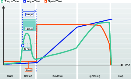
Parameter name | Description | Default value |
|---|---|---|
Selftap | Off: Selftap is turned off. On: Selftap is turned on. | Off |
Length | Defines the angle to turn the socket during Self-tap. Measured from the end of the Start step. | 360° |
Speed | Defines the speed during Selftap | 35 rpm |
Torque min | Torque value for lower Selftap limit. | 0 Nm |
Torque max | Torque value for upper Selftap limit. | Tool max torque |
Rundown Torque Limits
The friction between the screw and joint varies. This can cause the torque needed to run a screw down a thread, before engagement with the joint surface takes place, to vary as well. These effects could be, for example, hole interference, prevailing torque or varying lubrication.
Monitoring the rundown torque is useful when running down a lock nut or screw that has a plastic insert in the threads to help the fastener resist vibration. This will require a higher torque, known as prevailing torque, to overcome the interference.
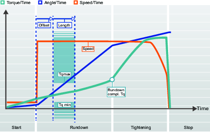
Parameter name | Description | Default value |
|---|---|---|
Rundown torque limits | Off: Rundown torque limits is turned off. On: Rundown torque limits is turned on. | Off |
Offset | Angle offset before the Angle interval begins. | 0° |
Length | Angle defining the Rundown torque limit section. | 360° |
Torque min | Torque value for lower Rundown torque limit. | 0 Nm |
Torque max | Torque value for upper Rundown torque limit. | 4.75 Nm |
Rundown Angle Limits
By monitoring the angle of rotation during rundown, errors such as screws with incorrect thread size or length are detected. For example, threads that are too long would require a greater turning angle for the screw to reach snug.
This option can be used if the target for the step is an angle value.
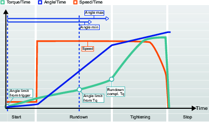
Parameter name | Condition | Description | Default value |
|---|---|---|---|
Rundown angle limits |
| Off: Rundown angle limits is turned off. From Trigger: Rundown angle limits is turned On. The system starts to monitor the tightening angle as soon as the tool trigger is pressed and reports if angle limits are violated. From torque: Rundown angle limits is turned On. The system starts to monitor the tightening angle from the specified torque value and reports if angle limits are violated. | Off |
Rundown angle monitoring torque | Rundown angle monitoring torque = From torque | Torque value from where Rundown angle limits are set. | 2.50 Nm |
Angle min | Rundown angle limits = On | Angle value for lower angle limit from starting point. | 100° |
Angle max | Rundown angle limits = On | Angle value for upper angle limit from starting point. | 1000° |
Time min | Rundown angle limits = On | Minimum time for the step. | 10 ms |
Time max | Rundown angle limits = On | Maximum time for the step. | 5000 ms |
Post View Torque
Some joints have a torque peak prior to Rundown complete. Post view torque makes it possible to monitor torque values during two specified angular intervals. The interval starts are defined as an angle prior to Rundown complete and torque is then monitored for a specified angular interval.
Post view torque is therefore similar to Rundown torque limits except that the maximum and minimum limits can be positioned independently of each other and can differ in length to better control the outcome of the rundown.
Monitoring the rundown post view torque is an option and controlled by a switch 
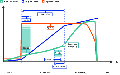
Parameter name | Condition | Description | Default value |
|---|---|---|---|
Post view torque |
| Post view torque is selected from a shortcut menu. Off: Post view torque is turned off. On: Post view torque is turned on. | Off |
Torque min | Post view torque = On | Torque value for lower Post view torque limit. | 4 Nm |
Torque min offset | Post view torque = On | Angle offset before the Post view torque min interval begins. | 720° |
Torque min length | Post view torque = On | Angle length defining the Post view torque min section | 90° |
Torque max | Post view torque = On | Torque value for upper Post view torque limit. |
|
Torque max offset | Post view torque = On | Angle offset before the Post view torque max interval begins. | 360° |
Torque max length | Post view torque = On | Angle length defining the Post view torque max section | 90° |
Compensate value | Post view torque = On | The Compensate value is selected fro a shortcut menu. Off: Peak torque On: Average torque |
Rundown Parameters
Parameter name | Condition | Description | Default value |
|---|---|---|---|
Self-tap |
| Self-tap is activated through a switch Off: Self-tap is turned off. On: Self-tap is turned on. | Off |
Length | Self-tap = On | Defines the angle to turn the socket during Self-tap. Measured from the end of the Start step. | 360° |
Speed | Self-tap = On | Defines the speed during Self-tap |
|
Torque min | Self-tap = On | Torque value for lower Self-tap limit. | 0 Nm |
Torque max | Self-tap = On | Torque value for upper Self-tap limit. | Tool max torque |
Rundown torque limits |
| Rundown torque limits is activated through a switch Off: Rundown torque limits is turned off. On: Rundown torque limits is turned on. | Off |
Offset | Rundown torque limits = On | Angle offset before the Angle interval begins. | 0° |
Length | Rundown torque limits = On | Angle defining the Rundown torque limit section. | 360° |
Torque min | Rundown torque limits = On | Torque value for lower Rundown torque limit. | 0 Nm |
Torque max | Rundown torque limits = On | Torque value for upper Rundown torque limit. | % of target torque |
Rundown angle limits |
| Rundown angle limits is selected from a shortcut menu. Off: Rundown angle limits is turned off. From Trigger: Rundown angle limits is turned On. The system starts to monitor the tightening angle as soon as the tool trigger is pressed and reports if angle limits are violated. From torque: Rundown angle limits is turned On. The system starts to monitor the tightening angle from the specified torque value and reports if angle limits are violated. | Off |
Rundown angle monitoring torque | Rundown angle monitoring torque = From torque | Torque value from where Rundown angle limits are set |
|
Angle min | Rundown angle limits = On | Angle value for lower angle limit from starting point | 100° |
Angle max | Rundown angle limits = On | Angle value for upper angle limit from starting point | 1000° |
Time min | Rundown angle limits = On | Minimum time for the step | 10 ms |
Time max | Rundown angle limits = On | Maximum time for the step | 5000 ms |
Post view torque |
| Post view torque is activated through a switch Off: Post view torque is turned off. On: Post view torque is turned on. | Off |
Torque min | Post view torque = On | Torque value for lower Post view torque limit. |
|
Torque min offset | Post view torque = On | Angle offset before the Post view torque min interval begins. | 720° |
Torque min length | Post view torque = On | Angle length defining the Post view torque min section | 90° |
Torque max | Post view torque = On | Torque value for upper Post view torque limit. |
|
Torque max offset | Post view torque = On | Angle offset before the Post view torque max interval begins. | 360° |
Torque max length | Post view torque = On | Angle length defining the Post view torque max section | 90° |
Compensate value | Post view torque = On | The Compensate value is selected from a shortcut menu. | |
Rundown complete torque |
| Defines the torque value for when snug is reached and the rundown is completed. The program can then move on to tightening the screw. Rundown complete must be less than First torque in multi-step strategies or Target torque in the TurboTight strategy. | 0° |
Time Monitoring
Time monitoring is available for most tightening strategies, but has some variations:
Time monitoring is not available for the Rotate strategy.
Time monitoring is available for the Rundown stage.
Time monitoring is available for the Final tightening step of the tightening stage.
Time monitoring is used in conjunction with angle monitoring. When angle monitoring is enabled or the final target is an angle value, time monitoring is available.
If the time limits are violated during either stage, the tightening is terminated. The NOK detailed reason result is set accordingly.
Detailed NOK reason
|
NOK reason |
Description |
|---|---|
|
Rundown time high |
The measured time from the activation time until rundown complete is higher than the time maximum limit. |
|
Rundown time low |
The measured time from the activation time until rundown complete is lower than the time minimum limit. |
|
Final tightening time high |
The measured time from the activation time until the tightening target reached is higher than the time maximum limit |
|
Final time tightening low |
The measured time from the activation time until the tightening target reached is lower than the time minimum limit |
Stop Stage
The stop stage terminates the tightening so that the socket can be released.
Soft stop causes the tightening to stop in a more ergonomic fashion. It is desirable for the tool not to stop within the time interval of 50-300 ms, as this is known to make it feel like an uncomfortable stop.
Parameter | Description | Default value |
|---|---|---|
Soft stop | Turns the Soft stop on or off. Off: No Soft stop is used. On: Soft stop is activated. When target torque is reached, the tools speed is immediately decreased to 75%. Then the speed is decreased to zero in at most 40 ms. | Off |
Loosening a Screw
By setting the loosening parameters, you can control the behavior of a loosening for a specific tightening program. Specify the loosening speed and torque to ensure that the screw is unscrewed as desired, so that the screw thread does not break, regardless of what tool is used.
A loosening is considered OK when Run-up torque is reached. Depending on variations in screw length, the system cannot determine when the screw has been run up completely. The operator will need to proceed with the loosening until it is considered finished.
The loosening is divided into normal loosening and TurboLoosening. The selection is made automatically based on tool capability and on the selected tightening strategy. TurboTight can achieve a much higher target torque and thus a normal loosening strategy is not sufficient. The TurboLoosening uses a pulsing strategy and is selected automatically, depending on whether the tool can support this.

Parameter name | Description |
|---|---|
Start | Run at slow speed. If the measured torque is below the detection torque, go to the run-up step. |
Loosening | For normal loosening: Run att slow speed until the measured torque is below the run-up torque, then proceed to the run-up step For Turboloosening: Loosen the screw by using as many pulses as needed until the measured torque is below the run-up torque, then proceed to the run-up step |
Run-up | Run the tool at the loosening speed, as long as desired. |
Parameter name | Description | Default value |
|---|---|---|
Loosening enabled | Selected by radio buttons. Off: Loosening is disabled. On: Loosening is enabled and additional parameters can be configured. | On |
Detection torque | Selected by radio buttons. Auto: The value is set based on the tool type and the tool capability. On:The value is set manually. | 7% ToolMaxTorque |
Detection torque | The minimum torque required to begin performing a loosening operation and produce a loosening result. | 3.5 Nm |
Run-up torque | Selected by radio buttons. Auto: The value is set based on the tool type and the tool capability. On:The value is set manually. | |
Run-up torque | When the torque falls below Run-up torque, the loosening is considered to be OK. Depending on variations in screw length, the system cannot determine when the screw has been run up completely. This is for the operator to decide. | 3.5% ToolMaxTorque |
Stage Parameter Descriptions
Target Torque Limits
By setting the Target torque limits, it is possible to discard a tightening should the torque result not fall within the specified torque limits. A torque set too high can cause the bolt to deform, break, or even strip the thread as a result of passing the yield point. Not enough torque can result in the clamping force not being sufficient to withstand the forces for which the joint is designed.
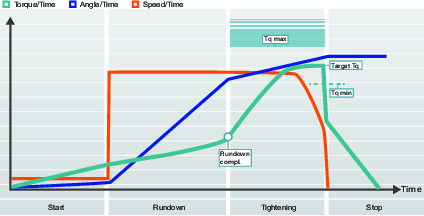
Target Angle Limits
With Target angle limits set, it is possible to monitor whether the nut is turned to the desired angle during the tightening.
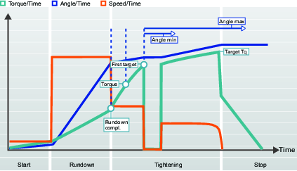
Torque Compensation
The graphical representation is used in the documentation to describe the configuration setting and the interpretation of the parameter values. The graphs are not used in the GUI of the controller or ToolsTalk 2.
By using torque compensation, the actual clamping force applied to the joint can be better determined and the scatter in the applied clamping force can be reduced.
The torque compensation point is set by referring back to a specified angle from Rundown complete and calculating a value for the torque used during rundown. This is then compensated for when creating the preload in the bolt by adding the torque value calculated in the torque compensation point to the Target torque.
Parameter | Description |
|---|---|
Torque compensation | Enables adjustment of the Target torque used in the rundown stage. Off: No compensation is made. On: Manually sets the Torque compensation point. |
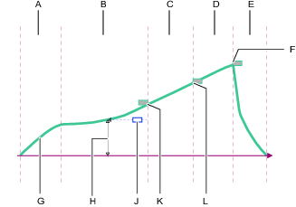
A | Start stage |
B | Rundown stage |
C | First step of the Tightening stage |
D | Final step of the Tightening stage |
E | Stop stage |
F | Final tightening target torque |
G | First tightening target torque |
H | Rundown complete target torque |
J | Torque compensation reference point (angle) |
K | Torque compensation value (torque) |
L | Torque over time curve |
The optional torque compensation parameter is found in the first tightening step in the tightening stage, but the measurement is done in the rundown stage. If enabled, the following happens:
A torque value is measured at a defined angle before rundown complete.
The measured value is defined as the torque compensation value.
The tightening continues into the first tightening step.
All the following torque values, like for example a target torque or an angle monitoring torque, are compensated with the addition of the torque compensation value.
Residual Torque Correlation Factor
The term Residual torque correlation factor is similar to a calibration and adjusts between the dynamic torque, measured in the electrical tool, and the residual torque, measured by a control tool.
The Residual torque correlation factor is available for all tools running the TurboTight strategy and the TensoPulse tightening strategy. It is also available for the battery pulse tools that are supported by the controller.
When using a Residual torque correlation factor that differs from 100, the reported Final torque is no longer the dynamic torque measured by the tool transducer.
The dynamic torque measurement uses an internal torque transducer that constantly measures the torque. When the target torque is reached, the tool stops and the result is evaluated and reported. The measured final torque in the transducer is affected by the joint condition, the tool speed, gears and sockets.
The residual torque is measured after the tightening is completed. It is the torque needed to continue or restart the tightening to a higher level. The residual torque is determining the clamping force in the joint.
A dynamic torque measurement is highly repetitive but may differ between tool type and tool speed. | A handheld calibrated torque wrench provides high accuracy measuring the residual torque but has higher variations due to joint relaxation, torque decay, friction or operator technique. |
The Residual torque correlation factor is a compensation between the dynamic torque and the residual torque. The factor should be determined by conducting tests. The selected tightening program is performed a few times and the dynamic torque is recorded. The tightenings are also manually measured to determine the residual torque.

The Residual torque correlation factor can be calculated by dividing a residual torque by a dynamic torque. TheResidual torque correlation factor is presented as percent and is by default 100%. This means the reported dynamic torque value has not been modified.
Parameters | Function |
|---|---|
Target torque | The tool target torque set for the tightening using the TurboTight strategy. |
Final dynamic torque | The final torque reported as the result of the performed tightening. |
Dynamic torque | The dynamic torque measured by a reference transducer. |
Residual torque | The desired residual torque that ensures the desired clamping force. |
Residual torque correlation factor | The compensation factor between residual torque and dynamic torque |
An example of how torque tuning can be used:
The TurboTight strategy is selected. The joint shall be tightened to 12 Nm to reach the desired clamping force. The following set up is made:
Example settings | Value | Function |
|---|---|---|
Target torque | 12 Nm | The programmed desired target torque in the controller |
Residual torque correlation factor | 100 | The compensation factor between residual torque and dynamic torque |
A number of tightenings are made. After each tightening the joint is checked with a calibrated torque wrench. The average is calculated and the following result has been found:
Initial parameters and results | Value | Function |
|---|---|---|
Target torque | 12 Nm | The programmed target torque in the controller. |
Final torque | 12 Nm | The final torque reported as the result of the performed tightening. |
Dynamic torque | 12 Nm | The uncompensated measured torque from the tool transducer. |
Residual torque | 10 Nm | The residual torque measured with a calibrated torque wrench or other test tool. |
Residual torque correlation factor | 100 % | The compensation factor between residual torque and dynamic torque |
The testing shows that the residual torque is too low to produce the desired clamp force. The Residual torque correlation factor is calculated to 0.83, which is 83 %. An adjustment of the tuning factor is made and the following result is obtained.
Final parameters and results | Value | Function |
|---|---|---|
Target torque | 12 Nm | The programmed target torque in the controller. |
Final torque | 12 Nm | The final torque reported as the result of the performed tightening. |
Dynamic torque | 14.5 Nm | The uncompensated measured torque from the tool transducer. |
Residual torque | 12 Nm | The desired residual torque that ensures the desired clamping force. |
Residual torque correlation factor | 83 % | The compensation factor between residual torque and dynamic torque. |
What this shows is that we need to tighten a bit more than the specified target, to compensate for differences and to reach the desired torque in the joint.
It is important that the correlation is made with the same tool type and parameter configuration that will be used in production.
Premature Torque Loss Detection
The tightening program moves from rundown to tightening when the screw head is snug and the torque increases rapidly. This point is refereed to as the Rundown torque and is defined by reaching the set torque value.
For a correct tightening, it is assumed that the torque increases. If the torque decreases, the following may be assumed:
The socket slips of the screw head while the tool trigger is still pressed. The tool detects rapid decrease in torque and continues to rotate according to its speed setting.
The screw breaks while the tool trigger is still pressed. The tool detects rapid decrease in torque and continues to rotate according to its speed setting.
If a decrease in torque is detected at this stage, proceed with the following:
Save the last torque value before a decrease is detected.
Start a detection timer.
Continue the tightening and measure the torque.
If the torque builds up and reaches the saved level and continues to build according to the tightening program within the set time period, then continue normally with the tightening
If the torque loss continues until the end of the set time period, the tightening is considered NOK.
If the tool detects the torque loss, it continues to spin freely as long as the tool trigger is pressed. The tightening is terminated when the operator releases the trigger and result is reported with detailed NOK reason = premature torque loss detected.
Creating a Tightening Program
If the list is empty, then no tightening programs have been created. Start by creating a new tightening program:
In the Plant structure
area, select a controller.Go to Tightening program
.The Tightening program overview displays a list of available tightening programs.
Select Add. The Create new Tightening Program window is displayed.
To create a new tightening program, enter the parameters described in the table below .
Select Add. The window closes and the workspace shows the configuration menu where more parameters must be added.
Parameter | Description |
|---|---|
Name | Issue the tightening program with a name in the parameter entry field. |
Index (Tightening program number) | The first free index number is given by default, but any other free number can be assigned to the tightening program. The index number can not be changed at a later stage. Enter an optional index number in the parameter entry field. |
Strategy | Select tightening strategy from the shortcut menu. |
Control strategy | Select from the shortcut menu. Only applicable to certain strategies. |
Target | Select to which final target the tightening shall be performed. Select from the shortcut menu. |
Target | Enter the target value(s) in torque and/or degrees for the tightening step. |
The available strategies depend on the IAM module and the controller software license.
Tightening Program Configuration - General Parameters
The Tightening program configuration menu contains some general parameters that are not directly part of the tightening program. These are described below:
All the parameters for a tightening program are entered and edited in the Step configuration menu.
Select a controller in the Plant structure
workspace .Select the Tightening program
tab.The Tightening program overview shows a list of tightening programs.
Double-click the name of one of the tightening programs in order to view and/or configure it.
The step configuration menu has two tabs: Tightening and Loosening.
Menu control | Description |
|---|---|
| Collapse the Properties menu. This provides better screen utilization. |
| Expand the Properties menu. This provides access to all the configurations. |
Parameter | Description | Default value |
|---|---|---|
Name | It is recommended to issue the tightening program with a unique name. The index number is created when the tightening is created and is fixed. The lowest available number is assigned to the program when it is created. | Program |
Description | An optional description of the tightening program. | |
Strategy | The available options depend on the controller software and license version. |
|
Direction | Thread direction defines the tightening direction of the spindle to clockwise (CW) or counterclockwise (CCW). The rotation of the spindle will always be in this direction, except during the loosening step used in the Three step strategy. | CW |
Rehit detection | Early: Terminates the tightening immediately when an already tightened screw/bolt is detected. The tightening will be considered as NOK. Requires that Soft start is activated. Complete: Even though an already tightened screw/bolt is detected, the tightening is not terminated until all tightening stages have been executed. The tightening will be considered as NOK. To make a rehit detection when Soft start is not used, the Rehit detection Complete option must be selected. Rehit detection Complete will not terminate the tightening until all tightening stages have been executed. The tightening will be considered a rehit if the speed fails to reach half of the rundown speed, a rehit error is then indicated. Off: No rehit detection will be performed. Combination Soft start = Off and Rehit = Early is not allowed | Early |
Current monitoring | Current monitoring provides extra security to monitor the tightening torque. This is a complement to the torque sensor in the tool. On: At final target torque, the rotor current is measured and converted to a torque value. If the calculated torque is within 10% of the measured torque, the tightening is considered to be OK. Off: Current monitoring is disabled and the tool torque is measured by the torque sensor. | |
True angle compensation | Certain tools can detect and measure the tool rotation during tightening. If the tool is rotated during tightening, the angle measurement may be corrupted. This may lead to a faulty tightening if the tool movement is too large. For variations within specified limits, the controller can compensate these rotations and make a correct tightening. This is an additional Licensed Feature, available per Virtual Station. | Off |
Negative angle limit | Active if True angle compensation is set to ON Defines the maximum negative rotation of the tool. If the value is exceeded the tightening is terminated and an error is reported. This is expressed in a numeric angle value. | 30 degrees |
Positive angle limit | Active if True angle compensation is set to ON Defines the maximum positive rotation of the tool. If the value is exceeded the tightening is terminated and an error is reported. This is expressed in a numeric angle value. | 30 degrees |
Attachment tuning enabled | Attachment tuning gives the possibility to compensate for front attachments on the tool. The compensation can be made for each tightening program. An operator can hot swap attachments and then select a tightening program tuned for that specific attachment. Attachment tuning is available for all conventional strategies, excluding the STwrench. Attachment tuning requires some special steps that are described separately. | No |
Validation
During the configuration of tightening programs, the entered values are compared with the tool capability values to prevent parameters being outside of the selected limits. User defined maximum values are useful if many different tools are being used.
If Validate against tool values is set to Off, these values are ignored, and the validations are made according to the maximum tool capability.
If Validate against tool values is set to On, then It shall be possible to choose a tool to validate the Tightening program(s) against from all the connected tools. The tool to validate against is done per client, giving the operator the possibility to validate against different tools from different clients.
Parameter | Description | Default value |
|---|---|---|
Tool | Manual | |
Max Torque | The maximum limit used in the validation. Can be selected to any value but it is recommended to use the actual tool value. This is expressed in a numeric torque value. | |
Max speed | The maximum limit used in the validation. Can be selected to any value but it is recommended to use the actual tool value. This is expressed in a numeric rpm value. |
A controller may have several virtual stations including tools that have different capabilities. The User defined values can be selected per each tightening program.
History
Tightening program history stores the last ten user changes. Select any stored version in order to see the parameter details. Activate the selected version by clicking Replace. To print all stored parameter history details of the selected tightening program, select History > Report > Print.
Select the Print button to open a shortcut window that displays all the current tightening program configurations and the parameter values. This window can be sent to a printer.
To print a stored tightening program, select a program in History and select the Report tab.
Tightening program validation
The ToolsTalk 2 application automatically compares the entered parameters with the parameter rules and the optional tool capabilities. If the validation detects any errors then these are reported together with an error description.
Some parameters have a default value when a new program is created. It may happen that tightening rules are violated and that the Error Indicator appears.
The Error indicator symbol. 
The location of Error indicator points towards the faulty parameter. Let the pointer hover over the Error indicator, a pop-up field explains which rule is violated. In the case of an error, change the parameter. When the parameter is correct the Error indicator will disappear.
Tightening Program History
ToolsTalk 2 keeps track of the last ten changes that have been made to a tightening program and pushed to the controller:
A printed report with all original tightening program parameter settings and the changes made.
A printed report with all current tightening program parameter settings.
A list of revision history for the tightening program. It is possible to quickly change to a previously tightening program parameter setting by selecting the desired version and clicking the Replace command button.
The revision history is created when a Push command is executed and the controller is updated from ToolsTalk 2.
Select a controller in the Plant structure workspace
. Select the Tightening program icon
.Double-click on a tightening program in order to open the tightening program configuration workspace.
Select the History command button.
The Managing Tightening Program History pop-up window opens.
Select the Changes tab.
The left side of the window shows a list of revision histories.
Click one row to select a revision.
The right side of the window shows a detailed list of the configuration parameters.
It is possible to compare two tightening program revisions. After selecting the first tightening program, hold the Control (Ctrl) button on the keyboard and select a second tightening program. The right side window then shows both settings. It is possible to show all parameters, or only the parameters that differ by selecting the Show only changes box.
When done, select the Close command button.
The pop-up window closes.
Select the Changes tab.
The left side of the window shows a list of revision histories.
Select two tightening programs from the stored tightening programs.
A comparison between the two selected tightening programs will be displayed in the column to the right.
Select the Close command button.
The pop-up window closes.
Select the Changes tab.
The left side of the window shows a list of revision histories.
Click one row to select a revision.
The right side of the window shows a detailed list of the configuration parameters.
Select the Replace command button.
Select the Close command button.
The pop-up window closes.
Select the Report tab.
Select the Print command button.
The print dialog window opens for printing.
When done, Select the Close command button.
The pop-up window closes.
The printed report contains a complete list of all configurations and parameter values. In addition to this, it lists all the revisions and the changes made in each of the revisions. This provides a complete history of what has been done in the Tightening program. The time stamp shows when changes were made, or when a push was done from ToolsTalk 2.
Attachment Tuning
Attachment tuning gives the possibility to compensate for front attachments on the tool. The compensation can be made for each tightening program.
An operator can hot swap an attachment and then select a tightening program tuned for that specific attachment.
Attachment tuning is available for all conventional strategies, excluding the STwrench.
Select a controller in the Plant structure workspace
.Select Tightening program
.The Tightening program overview shows a list of tightening programs.
Double-click the name of one of the tightening programs in order to view, or configure the program.
Select Attachment tuning enabled Yes or No in the Properties menu.
If this feature is disabled, the remaining parameters are invisible.
Go to the Step configuration menu and to the Start stage.
Select Use attachment tuning Yes or No.
If this feature is switched to Yes, the tuning factors are visible and can be edited.
The tuning parameters are:
Attachment gear ratio
Efficiency tuning
|
Attachment tuning |
Description |
Default |
|---|---|---|
|
Attachment gear ratio |
The Attachment gear ratio is needed to compensate the angle. Minimum: 0.5 Maximum: 3.6 Socket rotation speed = Tool speed / gear ratio |
1.0 |
|
Efficiency tuning |
Attachment gear ratio combined with the Efficiency tuning is needed to compensate the torque. Minimum: 0.5 Maximum: 1.0 For example 0.9 means 10% efficiency loss. |
1.0 |
CAUTION; The attachment gear ratio affects the tool speed and in turn, may affect the safety limits.
Importing a Tightening Program
A previously exported Tightening Program can be imported in a ToolsTalk 2 installation.
In the Plant structure
area, select a controller.Go to the Tightening program
tab.The Tightening Program overview displays a list of available tightening programs.
Select ADD. In the Create new Tightening Program dialog, select the Import tab.
Select Open file and locate the desired import file. The file must have the format json. Select ADD.
The imported Tightening Program is added to the list in the Tightening Program workspace.
Deleting a Tightening Program
Select the corresponding check box for each tightening program which is to be deleted.
Select Manage and then select Delete.
The list in the tightening program overview is updated.
Copying and Pasting a Tightening Program
Existing tightening programs can be copied as a template and then pasted on another controller.
Copy and Paste are only possible if they are performed on the same controller, or different controllers running the same software version and controller type.
In the Plant structure
area, select a controller.Go to Tightening Program
.The workspace area displays all the tightening programs available.
Right-click on a single row to be copied, or to copy many, select the check box
on each of the programs you want to copy, and then right-click.Select Copy.
Right-click anywhere in the empty workspace area, and then select Paste to add the tightening program to the first available position in the list. Alternatively, right-click and choose Paste with index to choose the position in the program list. Double-click to open the tightening program and modify.
It is also possible to paste the tightening program template into the Program Templates library workspace.
Global Tightening Program
A tightening program can be either Local or Global. If a tightening program is global, it is indicated with a Yes in the Library link column in the list of tightening programs.
In some documentation and in older GUI versions, the word tightening program may be substituted with the word Pset.
A Local tightening program is valid for a single controller.
Select a controller in the Plant structure workspace
.On the toolbar, select Tightening program
.The Tightening program overview shows a list of tightening programs.
A Local tightening program can only be edited via the Tightening program tab.
A Local tightening program is not visible in the Tightening program library .
A Global tightening program is valid for multiple controllers subscribing to the tightening program. If a Global tightening program is distributed to a controller, the controller will gray out the program so it cannot be modified, when using traditional strategies such as CATLA. When using multistep strategies, the program can still be edited but it will be overwritten if changes are made in ToolsTalk 2. The Global tightening programs are located in the tightening program library.
Select Library
in the left-side menu bar. Select Tightening program library
in the top menu bar. The Tightening program library shows a list of global tightening programs.
If a controller subscribes to a Global tightening program, it is visible in Tightening program , but editing is prohibited.
A Global tightening program can only be edited via the Tightening program library .
Converting a Local Tightening Program into a Global Tightening Program
In the list of local tightening programs, choose the program to convert by selecting the check box
in the leftmost column.Select Manage.
Select Add to library.
Select Create in the dialog window to copy the local tightening program to the library, this action will also close the window.
Clear the check box in the leftmost column.
The Library link column is marked with Yes for the selected tightening program.
ToolsTalk 2 can distinguish between a local and global tightening program, although the controller itself has no knowledge of this. Therefore it is important to specify the action in ToolsTalk 2 if a tightening program is changed via either the controller GUI, or the web GUI. This action is defined in the distribution of a global tightening program in the tightening program library.
Converting a Global Tightening Program into a Local Tightening Program
In the list of local tightening programs, choose the program to convert by selecting the check box
in the leftmost column.Select Manage.
Select Unlink.
Clear the check box in the leftmost column.
The Library link column is now empty for the selected tightening program.
Comparing Tightening Programs
It is possible to make a quick comparison between two tightening programs, when configured to the same strategy.
Select a controller in the Plant structure workspace
.On the toolbar, select Tightening program
.The Tightening program overview shows a list of tightening programs.
In the leftmost column, select the corresponding check boxes for both the tightening programs to be compared.
Select the Manage command button, and then select Compare.
If the two selected tightening programs do not have the same strategy, the comparison is not permitted.
The workspace displays a list of parameters for the two selected tightening programs. In the upper left corner the check box Show only differences can be selected to display only the parameters which differ.
Working with the Tools Tab
On the Tools tab , a list of tools connected to the controller is displayed. The menus displayed will differ between the controllers for fixtured tools, and the controllers for handheld tools, providing detailed information about the connected tools.
In the menu Settings, tool alarms can be set. Trigger points for these alarms are taken from the Tool menu.
Viewing the tool menu
Select a controller in the Plant structure workspace
.Go to the Tool
tab.A list of tools connected to the controller is displayed.
Double-click on one of the tools in the table for more detailed information and to access the Service Settings.
How to connect a tool or how to make a wireless pairing is described in the controller manual.
Column | Description |
|---|---|
Tool type | Describes the type of the tool. |
Model | A detailed model number of the tool. |
Serial number | The serial number of the tool. |
MAC address | The MAC address is only visible if the tool has got a MAC address. |
Software version | The software version of the tool. |
Max torque | The maximum torque value the tool can produce. |
Max torque with TurboTight | The maximum torque value the tool can produce when using the TurboTight strategy. Applicable only to certain tools. |
Max torque with TensorPulse | The maximum torque value the tool can produce when using the TensorPulse strategy. Applicable only to certain tools. |
Max speed | The maximum rotation speed of the tool. |
Next calibration | Date for the next calibration of the tool. |
Virtual station | The name of the virtual station to which the tool is connected. |
General information
The menu is valid for a controller that supports fixtured tools or handheld tools.
Information | Description |
|---|---|
Model | Tool model denomination. |
Serial number | Tool serial number. |
MAC address | The MAC address is only visible if the tools has got a MAC address. |
Product number | The same as ordering number. |
Software version | Tool software version number. |
If the tool is an STwrench, the following information is displayed:
Information | Description |
|---|---|
Model | Tool model denomination. |
Serial number | Tool serial number. |
STwrench serial number | Tool serial number. |
Software version | Tool software version number. |
Radio module software version | Software version number. |
The general tool information is provided by the tool itself to the controller and to ToolsTalk 2.
Limits
The menu is valid for a controller that supports fixtured tools or handheld tools.
Information | Description |
|---|---|
Gear ratio | The ratio of the angular velocity of the input gear to the angular velocity of the output gear. |
Max Torque | The maximum torque the tool can use for a tightening. |
Max Torque with Tensor Pulse | The maximum torque the tool can use for a tightening using the TensorPulse strategy. Applicable only to certain tools. |
Max Torque with TurboTight | The maximum torque the tool can use for a tightening using the TurboTight strategy. Only applicable for SR31 tools. |
Max speed | The maximum rotation speed of the tool. |
The tool limit information is provided by the tool itself to the controller and to ToolsTalk 2.
If the tool is a STwrench, the following information is available:
Information | Description |
|---|---|
Max Torque | The maximum torque the tool can use for a tightening or loosening. |
Min Torque | The minimum torque the tool can use for a tightening or loosening. |
Connection
Connection to the controller and to which virtual station it is assigned.
Calibration / Torque adjustment factor
The menu is valid for a controller that supports fixtured tools or handheld tools and is used to control how well a tool corresponds to a reference transducer and how to adjust differences.
The calibration value is stored in the tool's memory and is used to adjust the torque value given by the tool’s torque transducer so that the correct torque value is displayed on the controller. The controller displays last calibration date.
Tool calibration is carried out at the controller and uses a torque reference transducer. This process is described in the Power Focus 6000 controller manual.
Store the new calibration value in the tool's memory by entering the calculated value in the Calibration value parameter entry box, and then click Set.
Parameter | Description |
|---|---|
Last calibrated | Date for last calibration. |
Calibration value | Enter the measured and calculated value into the parameter entry box. |
Next calibration | Due date for next calibration. |
Set | Stores the entered values. |
If the tool is a TBP, the following information is displayed:
Parameter | Description |
|---|---|
Last calibrated | Date for last calibration. |
Torque adjustment factor | Enter the torque adjustment factor in %. |
Set | Stores the entered values. |
If the tool is a STwrench, the following information is displayed:
Parameter | Description |
|---|---|
Transducer calibration date | Date for last calibration. |
Gyro calibration date | Date for last calibration. |
Calibration alarm date |
|
Maintenance
The tool stores a service interval number and counts how many tightenings that can be performed before the next tool maintenance or service should be performed.
Parameter | Description |
|---|---|
Last service | Date and time when last service was performed. The last service date is set at the repair workshop. The Last service date is set to current date and time when the Reset button is pressed. |
Total tightenings at service | The Total tightenings at service is the total number of tightenings performed by the tool since it was first used. This value is updated at service, and will remain the same until the next service. |
Remaining tightenings | Total number of tightenings left until the service interval is reached. |
Service interval | Number of tightenings to be performed before the next service. Can be set in multiples of 10 000. |
Service interval pulses | pulse tools only] Number of pulses to be performed before the next service. Can be set in multiples of 10 000. |
Remaining pulses | [pulse tools only] Total number of pulses left until the service interval is reached. |
Reset service counter/data | The Reset command resets the counter and sets the Last service date to the current date. For TBP tools the oil status will also be reset. |
Set | The command stores the value entered in the Service interval parameter entry field and adjusts the value to a multiple of 10 000. |
Tool TAG information
This tool information is only available if the tool type is an STwrench.
Parameter | Description |
|---|---|
TAG id | The programmable RFID TAG identification number that is programmed into the End-fitting tool (Socket). |
Torque correction coefficient | In certain cases, extensions may be needed to fit the application. In this case the wrench measurement must be compensated to show a correct value. To calculate the correction coefficient, please refer to the STwrench user guide, printed matter nr 9836 4134 01 edition 2.12. The parameter is stored in the RFID TAG in the End-fitting tool. |
Angle correction coefficient | In certain cases, extensions may be needed to fit the application. In this case the wrench measurement must be compensated to show a correct value. To calculate the correction coefficient, please refer to the STwrench user guide, printed matter nr 9836 4134 01 edition 2.12. The parameter is stored in the RFID TAG in the End-fitting tool. |
Nominal torque | The smartHEAD of the STwrench contains the torque transducer and defines the wrench’s nominal torque, please refer to the STwrench user guide, printed matter nr 9836 4134 01 edition 2.12. |
Battery
The menu is available for battery tools. Shows battery information and battery health status.
Parameter | Description |
|---|---|
State of charge (0-4) | The more charged, the higher the number. |
State of health (0-2) | The better the health, the higher the number. |
Health
The menu provides data from environmental monitors. The equipment measures parameters regularly and stores them.
Parameter | Description | Value |
|---|---|---|
Refresh | Command button: read tool value. | |
History | Command button: History window opens to display latest temperature readings. | |
Tool motor temperature | Latest temperature recording expressed in month/day/year hours:minutes:seconds. | Degree C or F |
Tool electronics temperature | Latest temperature recording expressed in month/day/year hours:minutes:seconds. | Degree C or F |
Tool pulse unit temperature | Latest temperature recording expressed in month/day/year hours:minutes:seconds. | Degree C or F |
Zero offset and shunt limits
Only available for tools used with a StepSync controller
A tool can have one main and one secondary torque transducers. For each torque transducer, the limits show here.
Information | Description |
|---|---|
Shunt Limit | Maximum allowed measured shunt calibration value in %. |
Shunt Drift Limit | Maximum allowed change in measured shunt calibration value in %. |
Zero Offset Limit | Maximum allowed Zero offset compensation in %. |
Zero Offset Drift Limit | Maximum allowed change in the zero offset compensation in %. |
Handheld Tool Configuration
Handheld tools can have both standard functions, and accessory functions that provide signaling between an operator and the controller. The type of tool functions available depends on the tool model. In Tool configuration the signals are assigned to different functions.
A configuration is assigned to a tool and a tool is assigned to a virtual station.
This is described in the Configurations tab.
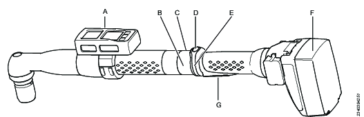
A | Tool accessory |
B | LED ring |
C | Blue LED on top |
D | Function button |
E | Direction ring |
F | Battery |
G | Tool trigger |
The following tool configuration parameters are available:
Blue led; a visual output signal.
Buzzer; an audio output signal that can produce different audio signals.
Direction switch; An input signal.
Function button; in a combination with the direction ring, six different input signals can be produced.
Tool accessory bus; different accessories can be configured with both input and output signals.
Tool LEDs; A ring of tool LEDs can be used to provide different output signals.
In addition, the tool configuration also defines how the tool is started and when tightening traces are recorded.
Viewing or Editing a Tool Configuration Menu:
Select a controller in the Plant structure workspace
. Select the Configurations
tab in the Menu bar.The workspace area displays the current accessory configurations.
Add a new configuration or double-click on an existing configuration with the type being a tool configuration.
Add the necessary configurations. The parameters are described in each section.
The tool configuration is divided into the following menus:
Menu | Description |
|---|---|
Properties | Configuration name and description and a tool type filter. |
General | General parameters for the tool. |
Buzzer | Output signal definitions for different tone signals. |
Direction switch | The direction switch is used as an input signal. |
Function button | The functional button together with the direction switch generates several different input signals. |
Tool LEDs | Output signal definitions for different LED signals. |
Accessory bus | Configuration of tool accessories. |
As the number of tools grows, the number of menus will grow as well. To increase the visual comfort in the workspace, it is possible to filter menus and only show what is relevant for one selected tool type. The filter is set in the Properties menu.
Tools - QA calibration
External tool configuration
Option | Function |
Enable | ON: Enables the external tool configuration option OFF: Disables the external tool configuration option. |
Virtual station | Connect the relevant Virtual station. |
Connection type | Connect via TCP port or Connect via COM port. |
TCP port | Visible when Connection type TCP port is selected. Shows the TCP port, pre-populated. |
COM port | Visible when Connection type COM port is selected. Shows a drop-down list with the available COM ports. |
Working with the Virtual Station Tab
The Virtual Station tab is located in the controller menu bar when a controller has been selected in the Plant structure
A virtual station is a software abstraction of a controller. Within one controller it is possible to create several virtual stations. Each virtual station behaves like a controller. The various configurations can be assigned to virtual stations as needed.
It is possible to select a task, assign accessory configurations, assign a tool, monitor and manipulate incoming and outgoing signals via diagnostics and set communication protocol parameters from the virtual station menu. The virtual station icon is available for both a FlexController and a Power Focus 6000 controller.
The virtual station concept is not valid for a FlexController. The software architectural design is maintained for both controller types, and therefore the virtual station appears in the FlexController interface.
Controller features, such as the Low Reaction Tightening Strategies and controller-wide functions among others, require licenses distributed through the Functionality Management System (FMS). Whereas configuration of features is possible without specific licenses, the assignment and use of those features will require the correct license to be installed on the controller. Please refer to Licenses (FMS) for more detailed information on licenses.
- Virtual Station Overview
- Assigning License Types and Features to a Virtual Station
- Assigning a Tool to a Virtual Station
- Assigning a Task to a Virtual Station
- Assigning Accessories to a Virtual Station
- Assigning a General Virtual Station Configuration
- Tool Configuration in a Virtual Station
- Virtual Station - Properties
- Fieldbus Mapping in a Virtual Station
- Virtual Station - Protocols
- Virtual Station - Diagnostics
- Virtual Station - Manual mode
Virtual Station Overview
To open the Virtual station workspace and view the list of virtual stations:
Select a controller in the Plant structure workspace
.Select the Virtual station
tab in the menu bar.The workspace area displays a list of virtual stations in the controller. The list is empty if no virtual stations have been created.
Column | Description |
|---|---|
Check box | Selects a virtual station. |
Name | Shows the name of the virtual station. |
Changed by | Which user that made changes |
Controller updated | Last time the controller was updated |
Controller updated by | Which user that has updated the controller |
Command | Description |
|---|---|
Add | Creates a new virtual station. |
Delete | Removes the selected virtual stations from the list. |
To access the virtual station configuration menu:
Navigating to Virtual station configuration
In the Plant structure workspace select a controller
. Select the Virtual Station tab
.
The virtual station overview shows a list of virtual stations for the selected controller. The list is empty if no virtual stations have been created.Double-click on a virtual station to open an existing configuration, or click Add to create a new virtual station configuration.
The following menus are displayed:
Menu | Description |
|---|---|
Properties | Issues the configuration a name and description. Optional. |
Protocols | Activation and configuration of external communication protocols. |
Tool | Assigns a tool to the virtual station. |
Tool configuration | Assigns a tool configuration to the virtual station. |
Fieldbus mapping | Displays a fieldbus mapping if it is configured and assigned to the controller. This field is information only. The actual fieldbus mapping and configuration is done in theFieldbus and SoftPLC
|
Task | Assigns a task to the virtual station or configures how a source signal selects the task to be performed. |
Accessories | Assigns an accessory configuration and an address to an accessory and assigns the combination to a virtual station. |
General | Used when assigning a General Virtual Station. |
Manual Mode | Used to configure the Manual Mode function. |
Licenses | Used for assigning and removing licenses and features to a virtual station. |
For a FlexController, only the Properties, Fieldbus mapping and Task menus are available.
Assigning License Types and Features to a Virtual Station
In the Virtual Station area licenses can be assigned to specific Virtual Stations. Select a controller from the Plant Structure
then select the Virtual Station tab. A list containing the different virtual stations is displayed.
Double-click on the row to be configured.
In Licenses configuration, select Virtual Station Type.
Select one of the following options:
Change to change the current type, a dialog window opens containing the available types.
Remove to remove the current type.
Choose to add a new type. Choose the type and select OK.
Double-click on the row to be configured.
In Licenses configuration, select Virtual Station Features.
Select one of the following options:
Add to add a new feature, a dialog window opens containing the available features . Choose the feature and select OK.
Remove to remove the current type.
Assigning a Tool to a Virtual Station
The Tool menu is used to assign a tool to the virtual station and provides information about the assigned tool.
Function | Description |
|---|---|
Model | Currently assigned tool to the virtual station. |
Max torque | Information only shown if a tool is connected to the controller and assigned to the virtual station. |
Software version | Information only shown if a tool is connected to the controller and assigned to the virtual station. |
Serial number | Information only shown if a tool is connected to the controller and assigned to the virtual station. |
MAC address | Information only shown if a tool with a MAC address is connected to the controller and assigned to the virtual station. |
Product number | Information only shown if a tool with a specified product number is connected to the controller and assigned to the virtual station. |
Unassign | Command button. Unassign a tool from the virtual station. |
Choose | Command button. Change the tool, or assign a new tool to the virtual station. A pop-up window opens for the tool selection task. |
A cable tool is connected to the controller via an electrical cable. A controller can have one cable tool connected.
A battery tool can be connected in three different ways:
Bluetooth - Using direct communication
WLAN (Ad-Hoc mode) - Using direct communication
Infrastructure mode - Using indirect communication within the plant's own network, via access points
Please see the specific Tool's Manual when configuring the communication settings.
Function | Description |
|---|---|
Wireless tool serial number | It is possible to assign a wireless tool to the virtual station that is not yet connected to the controller. A wireless tool is identified by its serial number, which can be entered in the data entry field. Wireless pairing, the process of connecting a wireless tool to a controller is described in the controller documentation. |
STB, SRB, TBP or STwrench | Select the desired tool type for a new wireless tool. |
Choose | Command button. Executes all the selections. |
Close | Closes the pop-up window without any changes. |
List of tools | The list contains all wireless tools currently connected to the controller. The virtual station column indicates if a tool is already assigned to a virtual station. If a cable tool is connected to the controller, it is also included in the list. |
Navigating to Virtual station configuration
In the Plant structure workspace select a controller
. Select the Virtual Station tab
.
The virtual station overview shows a list of virtual stations for the selected controller. The list is empty if no virtual stations have been created.Double-click on a virtual station to open an existing configuration, or click Add to create a new virtual station configuration.
Assigning a Tool
Select Choose in the Tool menu.
Select one tool from the list in the tool table, or type the serial number of a wireless tool that should be connected to the controller.
If a serial number is entered, select whether the wireless tool is an STB, SRB, TBP or an STwrench tool.
Enter Product number for the tool. This field is optional.
Select Choose.
Update the controller via the Push function.
It is important to assign both a tool and a tool configuration to a virtual station. Tool configurations are created in the Configuration section .
Assigning a Task to a Virtual Station
The Task menu in theVirtual station workspace is used to select and assign tasks.
The menu is available for both a Power Focus 6000 controller and a FlexController, but the functionality is different.
Function | Description |
|---|---|
Name | Currently assigned task to the virtual station. The field is empty if no task is selected. Pressing the trigger will result in the event number 4025 No Tightening program selected . An error indicator can appear beside the name |
Unassign | Command button. Deselects any task from the virtual station. |
Choose | Command button. Change the task manually or configure external sources to select a task. The Choose task pop-up window opens to configure the task selection. |
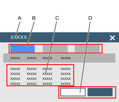
A | Choose task pop-up window. | B | Selection tabs.
|
C | List of available tasks:
| D | Command button Choose. Command button Close. |
Navigating to Virtual station configuration
In the Plant structure workspace select a controller
. Select the Virtual Station tab
.
The virtual station overview shows a list of virtual stations for the selected controller. The list is empty if no virtual stations have been created.Double-click on a virtual station to open an existing configuration, or click Add to create a new virtual station configuration.
Assigning a Task
Select Choose in the Task menu.
The Choose task pop-up window appears.
Select one tab and select one item from the list:
Tightening program: Select from a list of tightening programs available in the controller.
Batch: Select from a list of batch sequences available in the controller.
Sources: Select from a list of source tasks available in the controller.
For fixtured tools using the FlexController, only Sources is available and only one line - Multi Spindle Tightening, can be selected.
Select Choose. The Choose task pop-up window is closed.
The Close button closes the pop-up window without making any changes.
Update the controller via the Push function.
The name field is updated in the Task menu.
The task selection using sources and identifier numbers and identifier strings to select a task is described in detail in the documentation for the sources configuration.
Assigning Accessories to a Virtual Station
This menu is only valid for a controller that supports a handheld tool.
A controller may have several accessories connected through a CAN bus. Each accessory must have a unique address on the bus within the range 1-15. It is possible to assign several accessories to a virtual station.
An accessory must have an accessory configuration assigned to it, before it is possible to assign the accessory to the virtual station.
To view the current accessory assignment to a virtual station:
Navigating to Virtual station configuration
In the Plant structure workspace select a controller
. Select the Virtual Station tab
.
The virtual station overview shows a list of virtual stations for the selected controller. The list is empty if no virtual stations have been created.Double-click on a virtual station to open an existing configuration, or click Add to create a new virtual station configuration.
Function | Description |
|---|---|
Check box | Selects an accessory configuration that can be unassigned from the virtual station. |
Name | Name of the configuration assigned to the accessory. |
Type | Type of accessory. |
CAN node | The CAN address of the accessory. |
Serial number | The serial number of the accessory. |
Status | Can be either:
|
The CAN node column shows the used addresses which can not be used when new accessories are connected. An assignment for a socket selector can include multiple addresses.
For socket selectors the order of the CAN nodes is important. The lowest position in the first socket selector is the first position in the assignment.
Function | Description |
|---|---|
Unassign | The selected accessory is unassigned from the virtual station. The accessory remains connected to the controller. |
Choose | Adds a new accessory. The Accessories pop-up window opens. |
Diagnose | Monitoring of I/O signal behavior and possibility to force signals to a desired state between controller internal logic and the accessory. |
Adding an accessory to a Virtual Station
The selected accessory must have a unique and valid CAN bus address. An accessory configuration is assigned to an accessory and the accessory is assigned to a virtual station.
Navigating to Virtual station configuration
In the Plant structure workspace select a controller
. Select the Virtual Station tab
.
The virtual station overview shows a list of virtual stations for the selected controller. The list is empty if no virtual stations have been created.Double-click on a virtual station to open an existing configuration, or click Add to create a new virtual station configuration.
To assign an accessory to the virtual station:
Select the Choose button in the Accessories menu to open up the Accessories pop-up window.
Select an accessory type from one of the tabs.
Check
to select a configuration in the list of Configurations. Check
to select an address in the list of Available CAN nodes. It is possible to connect several socket selectors to a controller. Each of the socket selectors have a unique CAN address. It is possible to assign one configuration to all socket selectors. The CAN node order becomes important to define the sockets in the correct order. The socket selector that has the lowest order position must be selected first, followed by rising order.
Select the Choose button and add one of the accessory options.
Repeat the procedure for each accessory that is to be assigned to the virtual station.
Select the Cancel button to close the pop-up window.
The Accessories menu is updated and shows new assigned configurations.
An accessory address is set by a rotary switch on the accessory. See detailed product information documents for the accessory. Accessory address range is between 1 and 15.
Unassigning an Accessory from a Virtual Station
To unassign an accessory configuration and remove the connection to a virtual station, perform the following steps:
Navigating to Virtual station configuration
In the Plant structure workspace select a controller
. Select the Virtual Station tab
.
The virtual station overview shows a list of virtual stations for the selected controller. The list is empty if no virtual stations have been created.Double-click on a virtual station to open an existing configuration, or click Add to create a new virtual station configuration.
Mark the check box of the accessory configurations that is to be unassigned in the Accessories menu.
Select the Unassign command button in the Accessories menu.
To update the controller with any changes, select the Push changes command button
.
The list in the accessory menu will be updated.
Configuring I/O
I/O Diagnostics is used to troubleshoot external hardware and to test PF6000 configuration. The operator is able to troubleshoot a station that is not behaving correctly. A station's behavior is not only defined by its software, hardware and configuration, but the combined state of all its inputs and outputs. Therefore it is often helpful to get an overview of input and output states. This can for example aid in finding the following problems:
Hardware malfunctions in the accessories (lamps/cables/buttons etc.)
Suspicion that inputs are not properly received from surrounding systems.
Suspicion that outputs are not properly sent to surrounding systems.
To access the I/O diagnose function:
Select a controller in the Plant structure workspace
. Select virtual station
in the Menu bar of the controller workspace.The workspace area displays a list of virtual stations in the controller. The list is empty if no virtual stations have been created.
Double-click on a virtual station name to open an existing virtual station configuration or click Add to create a new one.
The workspace shows the menus, including Accessories assigned to that specific virtual station.
Select the check box
for the device to be diagnosed. The device has to be in status Connected.Select Diagnose.
The I/O diagnostics function provides the possibility to Monitor the incoming and outgoing signals, sent to and received from the selected device. It is also possible to manipulate the information via Forced mode.
I/O diagnostics can be used from:
Controller GUI
Web GUI
ToolsTalk
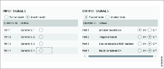
Diagnostics mode | Activate Monitor mode or Forced mode. Monitor mode: In monitoring mode it is possible to see status of all configured fields in the incoming and outgoing signals, sent to and received from the device. Whenever there is a change in a signal, the view is updated. Forced mode: When in forced mode, the signals are frozen in their current state and will be possible to manipulate from the client. The operator can now activate and deactivate signals individually. The change of signal value in forced mode is immediately propagated to the controller. When leaving forced mode all forced signals will be set to their actual values, that is, the values they would have had if no forcing had been performed. |
Component | The column Component lists the parts of the device where to connect the incoming/outgoing signals. |
Signal | List of signals configured for the selected device. If no signal is configured, the field displays the text "None". |
Only one diagnostics session can be active at a time and only one device at a time can be in diagnostics state. If the diagnostics is already in use, an information message is shown on the screen.
Assigning a General Virtual Station Configuration
Navigating to Virtual station configuration
In the Plant structure workspace select a controller
. Select the Virtual Station tab
.
The virtual station overview shows a list of virtual stations for the selected controller. The list is empty if no virtual stations have been created.Double-click on a virtual station to open an existing configuration, or click Add to create a new virtual station configuration.
To assign a General configuration to the virtual station
In the virtual station configuration workspace, go to the General area.
Select Change. In the pop-up window: The listed General configurations are the ones added in Configurations
.Select one of the general configurations and select the Change button.
The General menu is updated with the selected general configuration.
Only unassigned general virtual station configurations can be deleted.
Tool Configuration in a Virtual Station
This menu is only visible for a Power Focus 6000 controller using handheld tools.
A tool may have several configurations of the tool accessories. Tool accessories are for example the LED’s, push buttons, buzzers and direction rings. Digital I/O signals can be configured to interact with the operator. The tool accessory configuration is made in the Configurations menu .
Function | Description |
|---|---|
Name | Name of the tool configuration. |
Tool type | The Tool type filter can be used to show configurations for selected tools. The filter is set when tool accessories are configured in Configurations
|
Description | The optional tool configuration description field. |
Change | Assigns the selected tool configuration to the tool assigned to the selected virtual station. |
Close | Closes the pop-up window without saving any changes. |
| The list of configurations can be sorted alphabetically. Click on the arrow to change the sorting direction. |
Navigating to Virtual station configuration
In the Plant structure workspace select a controller
. Select the Virtual Station tab
.
The virtual station overview shows a list of virtual stations for the selected controller. The list is empty if no virtual stations have been created.Double-click on a virtual station to open an existing configuration, or click Add to create a new virtual station configuration.
:
Selecting a Tool Configuration
Select Change in the Tool configuration menu.
The Select tool configuration pop-up window appears, listing the available tool configurations.
Select one row of tool configurations and select Change in the pop-up window.
The Select tool configuration pop-up window disappears.
The Tool configuration menu shows the selected configuration name.
If a tool filter is used in the tool accessory configuration AND a tool is connected and assigned to the virtual station, the Tool type column shows only relevant configurations, and the list is reduced to selectable configurations.
If no tool is assigned to the virtual station or no tool filter is used, all tool configurations are shown in the list.
Virtual Station - Properties
A virtual station must have a name. This is configured in the Properties menu. The default name is Virtual station <index nr>. An optional description field is also available.
If the name field is left blank, a red error indicator is displayed .
Fieldbus Mapping in a Virtual Station
A controller may have one Fieldbus communication module installed. This communication module serves all the virtual stations. The Fieldbus mapping menu shows which fieldbus configuration is mapped to the controller. Fieldbus is configured and the configurations are assigned and mapped in Fieldbus and SoftPLC
Fieldbus Diagnostics
To access the Fieldbus mapping diagnose function:
Select a controller in the Plant structure workspace
. Go to Virtual Station
.The workspace area displays a list of virtual stations in the controller. The list is empty if no virtual stations have been created.
Double-click on a virtual station name to open an existing configuration or select Add to create a new virtual station configuration.
The workspace shows the menu, including mapped fieldbus.
Click the Diagnose button to enter the Fieldbus diagnose function.
The fieldbus diagnostics function provides the possibility to Monitor the incoming and outgoing signals, sent to and received from the fieldbus. It is also possible to manipulate the information, compose and send frames, via Forced mode. Fieldbus diagnostics can be used from:
Controller GUI
Web GUI
ToolsTalk
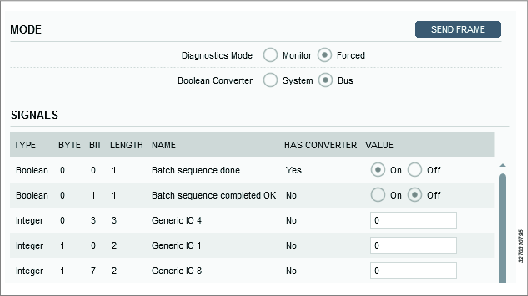
Diagnostics mode | Activate Monitor mode or Forced mode. Monitor mode: In monitoring mode it is possible to see the status of all configured fields in the incoming and outgoing frames, sent to and received from the fieldbus. Whenever there is a change in any of the bits of a received frame, the view is updated. Forced mode: When entering forced mode, the data will freeze in its current state, the frame is locked. In forced mode it is possible to activate and deactivate signals manually, or enter values and force them on one or more signals. This is possible on the incoming frame, the outgoing frame, or both. |
Boolean converter | Switch between System view and Bus view. The converter makes it possible to invert the signals sent to or received from the fieldbus. |
Type | Type of signal. |
Byte | Location in frame. |
Bit | Location in frame. |
Length | Length of signal in frame. |
Name | Name of signal. |
Has converter | Has converter is Yes if any converter is configured. If Yes, the converter can be used to invert the signal. If No, the converter is not applicable. |
Value | The Value column shows a list of signals and their values. The value of each signal in the incoming and outgoing frame is seen in the following formats: boolean, integer or string, depending on type. The values are editable in Forced mode. It is possible to change one signal, a few signals or all signals in the same frame. After changing the values, click Send frame button for the new frame to be pushed to the controller and for the new values to be applied. When leaving diagnostics mode, all values are reverted to as they were in the last saved frame of incoming and outgoing signals. |
Only one diagnostics session can be active at a time. If the diagnostics is already in use, an information message is shown on the screen.
Virtual Station - Protocols
The Protocols menu may contain one or more implemented communication protocols and their parameter settings. The availability of protocols depends on the IAM license.
Customer specific communication protocols are also configured in the Protocols menu.
Open Protocol
Configuring Open Protocol
In the Plant structure workspace
select a controller.Select the Virtual Station tab
.
The virtual station overview shows a list of virtual stations for the selected controller. The list is empty if no virtual stations have been created.Double-click on a virtual station to open an existing configuration, or select Add to create a new virtual station configuration.
Select Configure in the Protocols menu.
The virtual station Open protocol configuration switch allows a user to enable or to disable Open protocol communication between a virtual station and the integrator, which is part of the factory control equipment.
The Open protocol uses the same factory ethernet connection on the controller that is used for configuration or for delivering tightening results.
Each virtual station is uniquely identified by a port number. For each virtual station using the open protocol, a port number must be entered in the Port field.
If the open protocol is used to select the task, the Disconnect setting controls the actions to be taken when the communication between the virtual station and the client is lost:
None: If the system loses connection towards the Open Protocol client, no action will be taken and any selected task will be able to continue with normal operation.
Unassign task: If the system loses the connection towards the Open Protocol the selected task will be deselected, the tool will not be locked
If an open protocol error occurs, the current tightening is finished and the task ends. The current task is deselected from the virtual station.
If a communication error occurs, the current tightening is finished and the task ends. The current task is aborted but not deselected from the virtual station.
Lock tool active high: If the system loses connection towards the Open Protocol the tool will be locked.
When the Open Protocol connection is restored, the tool will remain locked. In order to resume normal operation the tool has to be unlocked using MID 0043 (Enable tool) or IO signal Master unlock.
The task will not be deselected when Lock tool option has been selected.
Always lock tool: If the system loses connection towards the Open Protocol the tool will be locked, regardless whether the used task is selected via Open Protocol or not.
When the Open Protocol connection is restored, the Tightening program and Sequence task have to be selected to resume normal operation.
When the Open Protocol connection is restored the tool will remain locked. In order to resume normal operation the tool has to be unlocked using MID 0043 (Enable tool) or IO signal Master unlock
The legacy counter setting counts all tightenings in a sequence and outputs that number to secondary systems. To enable this setting, set Use legacy counter to On.
SoftPLC Index is used to map where in the shared memory the Open Protocol commands are to be written. The default value is 1 but it is possible to enter values 1 to 6.
As the default value for SoftPLC Index is always 1 and no check is made to see if it is in use, there is a possibility that you may have configured the system so that the same index is configured several times when adding Virtual stations. In this case the Soft PLC will not be able to determine from which Virtual Station the incoming MID is originating from.
Virtual Station - Diagnostics
The diagnostics are available for both I/O and Fieldbus configurations.
For I/O diagnostics, for further information, see Relevant Information in the User Guide.
For fieldbus diagnostics, for further information, see Relevant Information in the User Guide.
Digital Signal Diagnostics
During deployment and during troubleshooting of a controller, a diagnostic tool is very helpful. It is available for the analysis under the Info tag for a device configuration or a fieldbus mapping in the Virtual station menu.
The controller can operate in normal mode or in diagnostics mode. In normal mode the digital input and output signals operate normally and are routed between the internal controller logic and to an external accessory or a connector.
The diagnostics mode is divided into monitor mode and forced mode. In the monitor mode signals operate normally, but provide live monitoring of the signal behavior. In forced mode the connection between the controller internal logic and the external accessory is opened and the input and output signals can be forced to a desired state.
It is possible to diagnose digital signals for one device or one fieldbus at a time.
Normal Operations
In normal operations mode external input signals are passed to the internal controller logic and controller output signals are passed to an external target, without any intervention from the diagnostics module.
A | Controller internal state machine and logic functions |
B | Digital output signal path |
C | Digital input signal path |
D | Diagnostics module |
Monitor Digital Signals
In the diagnostics mode all signals passed to and from the controller internal logic can be monitored. A signal tap is connected in the diagnostics module and the signal states are displayed on the web GUI or the controller GUI.
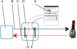
A | Controller internal state machine and logic functions |
B | Digital output signal path |
C | Digital input signal path |
D | Diagnostics module |
E | User interface |
F | Output signal tap |
G | Input signal tap |
Force Digital Signals
In the diagnostics mode all signals passed to and from the controller internal logic can be forced to a desired state. The signal lines are opened in the diagnostics module. From the user interface both input and output signals can be forced to steady states. The user interface is either the web GUI or the controller GUI.
While signals are forced, the controller operates normally. When leaving the diagnostics mode and the forced mode all signals are set to the current operating state of the controller. This may lead to a change-of-state for digital outputs, which can create unwanted actions.
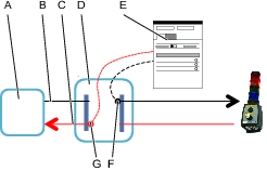
A | Controller internal state machine and logic functions |
B | Digital output signal path |
C | Digital input signal path |
D | Diagnostics module |
E | User interface |
F | Forced output signal insertion point |
G | Forced input signal insertion point |
Virtual Station - Manual mode
Manual mode for Virtual Stations is used for performing tasks while the tool is in locked mode. In cases where the tool is locked for a certain reason (for example, because the tool is outside its TLS footprint) there still may be a need to perform certain tasks with the tool, such as performing emergency work. By configuring manual mode for the Virtual Station, users can determine what signals are sent when entering manual mode (Entering signals), what task can be performed while in manual mode (Secondary task), and what signals are sent when leaving manual mode (Leaving signals).
Since desired scenarios can vary between different users (that is, which signals to send upon entry and exit and what task to perform), manual mode is fully configurable for each Virtual Station.
Configuring Manual Mode
Configuration consists of three elements: entering signals, leaving signals and secondary task (note that by primary task is meant the "automatic" task that is assigned to the virtual station under Task). If no secondary task is selected, the primary task will be run.
Go to the Virtual station menu, select the virtual station to configure, and then under Manual Mode, select Configure.
In the Manual mode configuration screen, set the secondary Task. This determines which task should be run when in manual mode.
The same tasks (tightening, batch sequence, source) can be set for the secondary task as for the primary task.
Set the entering signals to be sent by selecting the Add button.
Set the leaving signals to be sent by selecting the Add button.
There is a limit set to 99 signals to be sent for entering and leaving.
The parameters for entering and leaving signals are the same.
Triggering Manual Mode
Manual Mode can be activated by a switch or an external system. For example (indicated below), a key switch on an operator panel can be configured to activate manual mode.
Go to the Configurations menu and choose Operator panel .
In the configuration window, go to the position [A,B,C,D,E,F,G,I] to configure and in the list, choose One way key switch.
Select on the Turn signal list. In the list, choose Manual mode.
Close the window.
If the user needs to be notified that Manual mode has been entered or left, then events 4070 and 4071 have to be configured, respectively. This is done in Settings - Events.
Reports
In this section, you can learn about available reports.
Working with the Results Tab
ToolsTalk 2 has the capability to show more detailed tightening results than the controller GUI.
Tightening results from the controller are automatically sent from the controller to ToolsTalk 2 as soon as the tightening is finished.
The controller has also the option to send the tightening results to ToolsNet 8 for further processing and statistical analysis.
In ToolsTalk 2 it is possible to view the results and to create reports from one controller at a time. Each task is displayed as one result. A single tightening can show results in a table with key parameters or as a tightening graph. A batch sequence shows all the individual tightenings in the order in which they were performed.
Statistical analysis, result filtering and tightening analysis can be performed using ToolsNet 8. More information on how this is done is described in the ToolsNet 8 documentation.
Icon | Description |
|---|---|
 | The workspace area shows tightening results from the selected controller. The results can be shown both in table format and in graphical traces. |
Results can only be sent and displayed while there is an active connection to the server. If tightenings are performed while the server is offline, then these results will not be transmitted to ToolsTalk 2 during this period.
Handling Results
Latest results tab - Displays the results for the latest tightenings.
Search Results tab - Use the Search button to search for results between specific dates.
Pinned tab - For investigation.
A tightening result can temporarily be stored into the Pinned tab. This is useful for detailed analysis of a tightening, and prevents the tightening result to be dropped from the window as new results are received.
Live results tab - A controller sends tightening results to ToolsTalk 2 as soon as the task is completed, and the result is added to the top of the Live results. A limited number of results can be stored. When the list is full, the oldest result is dropped from the list.
Imported results tab - For viewing imported results.
Pinned - Holding area for investigation
Tightening results can temporarily be stored into the Pinned area. This is useful for detailed analysis of a tightening, and prevents the tightening result to be dropped from the window as new results are received.
Manually: On a result, select the Pin icon.

The tightening result is copied to the Pinned area for investigations. It is possible to pin several results to the temporary storage.
Automated: Select the Auto pin drop-down menu and enter number of results to be pinned. Select Start. The next incoming result will be pinned automatically, continuing until the entered number has been reached, or until pressing Stop.
Remove all results from the pinned area
To remove individual results, unpin it by selecting the Pin icon .
Live results
A controller sends tightening results to ToolsTalk as soon as the task is completed, and the result is added to the top of the Live results. A limited number of results can be stored. When the list is full, the oldest result is dropped from the list.
Each line in the list represents one task and can be a single tightening or a batch sequence, depending on the selected task. Expand the list to view a more detailed information about each tightening.
Use the arrows to expand the overview result to a more detailed result view or to collapse the view to only display the overview result.

Column | Description |
|---|---|
Red bar | The leftmost position in the Live results table may contain a red bar icon , indicating erroneous tightenings for quick identification of errors. This corresponds to NOK. |
Holding pin | Select the holding pin icon to pin the result to the pinned tab. |
Trace | Select the trace icon to view a graphical view of the results in the Trace workspace. |
Save icon | This command creates a .csv file with the trace data. A dialog window is opened as to save the file in a desired location, where it can later be imported from. |
Overall Status | OK or NOK. NOK is always in combination with the red bar icon, to quickly identify erroneous tightenings. Incomplete tightenings will have the word Stopped next to the result. |
Type of task | Shows if the performed task is a single tightening or a batch sequence. |
Virtual station name | Name of the virtual station. |
Scan sequence | If a scanner was used to select the task, the scanned sequence is displayed. Otherwise the column is empty. |
Task name | The name of the tightening or the batch sequence. |
Time Stamp | Time stamp for the tightening, that is, time and date. |


Result parameter | Description |
|---|---|
Trace | Select the trace icon to view a graphical view of the results in the Trace workspace. |
Save | This command creates a .csv file with the trace data. A dialog window is opened as to save the file in a desired location, where it can later be imported from. |
Status | This column can show either OK or NOK. NOK is always displayed in combination with red text in the ToolsTalk 2 user interface. |
Status info | Additional tightening information. |
Tightening name | The name of the tightening. |
Torque Low Limit | The Low limit which is set in the Step Monitor Peak Torque, that reports Final Torque. |
Final Torque | Final Torque for the tightening. It is the Step Monitor Peak Torque located in the last tightening step that reports this Parameter. |
Target Torque | The Target Torque will display the Target Torque value configured for the tightening strategy, which is used to perform the tightening. |
Torque High Limit | The High limit which is set in the Step Monitor Peak Torque, that reports Final Torque. |
Rundown Angle | If rundown is enabled there will be a Rundown Angle value presented in the result. |
Angle Low Limit | The Low limit which is set in the Step Monitor Angle, that reports Final Angle. |
Final Angle | The actual measured angle of the last tightening step It is the Step Monitor Peak Angle located in the last tightening step that reports this parameter. |
Target Angle | The Target Angle will display the Target Angle value configured for the tightening strategy, which is used to perform the tightening. |
Angle High Limit | The High limit which is set in the Step Monitor Angle, that reports Final Angle. |
TrueAngle Compensation | The TrueAngle compensation will display the compensated angle. |
Start Final Angle | The Start Final Angle will display the torque value from where the Final Angle was initiated. |
Primary error | Primary error of why the result is NOK. |
Failing Step | Indicates the number of the step that detected the first error in case of a NOK tightening. |
Batch | The column is only displayed if the task is a batch sequence. The number indicates the order number of the batch within the batch sequence. |
Batch count | The column is only displayed if the task is a batch sequence. The number indicates the order number of the tightening within the batch. |
Angle and Torque results | Numeric value. Only shown if used as a target value or as a limit value. |
Errors | Shows all errors. |
Elapsed time | Time from tightening start to end. |
Detailed status | For NOK results, additional information about the error is shown. |
Result Reporter
The list shows the values from the result reporters. If there is a result reporter defined for a program monitor/restriction, the value from that monitor/restriction is reported. If there is no result reporter defined for a program monitor/restriction, the value from the latest executed step in main path with a reporter is reported.
Monitors / Restrictions results for multistep
Each step in the multistep tightening program reports data. Most of this data is coming from the monitors and restrictions that are active during the step, so the data is only reported if a monitor or restriction of the correct type is configured.
Step Result Parameter | Description |
|---|---|
Step | The number of the step. |
Status | Status of the step, OK or NOK. |
Step type | Step type in the multistep program. |
Step category | For each step, there is an option to choose a step category. These categories can be customized. By selecting step category, the NOK tightenings will be listed in the event result view with related detailed status together with the corresponding multistep error information. If no selection is made, the detailed status will be set to "uncategorized multistep error". |
Primary error | Primary error of why the result is NOK. |
Elapsed time | Time from tightening start to end. |
Errors | Shows all errors. |
Trace results
The Results workspace shows detailed and graphical information on one or several tightening results.
The tightening results are displayed in a collapsed list that can be individually or collectively chosen for further analysis in the Trace workspace.
Trace results graph
If the controller provides Trace results, a graphical view of the tightening can be displayed. On a result, select the Trace icon if it is active  . If the trace icon is grey
  , then no trace data has been sent from the controller. A trace result must be sent from the controller. Trace configuration options are set in General menu when a tool configuration is selected in the Configurations section .
The tightening result is copied to the graph area for further investigation and the result graph is displayed. It is possible to view several tightening results as graphs simultaneously.
Trace settings/preferences | Description |
|---|---|
Show limits | Limit values can be shown if they are used in the tightening program. |
Show Min/Max | Show minimum or maximum measured value. |
Peak Sync | Some curves may look the same, but are placed differently in the graph. This option creates an overlay of the curves and synchronizes their peak values. |
Manual Sync | |
|X-Axis| | Show the absolute value for X-axis. |
Y1 | Choose the information to be shown in the Y1-axis:
|
Y2 | Choose the information to be shown in the Y2-axis:
|
Y3 | Choose the information to be shown in the Y3-axis:
|
X | Choose which information to be shown X-axis:
|
Supported trace plots | Information on the trace’s axis:
|
Remove All Δ | Remove all the deltas. |
Save... | This command creates a picture of the graphical area. A dialog box is opened to save the file in a desired location. The file name is by default export.png. |
Remove All | This button clears the trace plot area. The traces are still in the results and can be accessed again via the "live results" workspace. |
Searching for Results
Use the Search function to search for results between specific dates.
Go to the Results tab
.Select the sub-tab Search Results.
Select the Search... button to open the Result search settings dialog.
In Date range, select either a from and to date on the calendar, or a predefined range via the drop-down. Select Search when ready.
Search results will be displayed in the sub-tab Search Results, for further action or analysis.
Switching between controllers will clear the results from the Search Results sub-tab.
Exporting Results
Export to a spreadsheet, select the source and number of results to export. All the details from one or more tightenings can be exported.
Select the Export button.
Select where to export from:
Export from latest: Exports a selected amount of results from the last received results.
Export from pinned: Exports a selected amount of results from the temporary storage area.
Export from controller: Exports a selected amount of results from the controller.
Amount of results: Enter number (amount) of results to export. The results are first taken from the top of the list and then downwards.
Select Export.
A dialog box opens for selecting the storage location.
Select Save.
Importing Results
Select the Import button.
In the dialog window, select the .csv file to be imported.
Select Open.
The imported trace is added to the list in the Imported tab.
StepSync Results
The tightening results are displayed in a condensed list that can be individually or collectively chosen for further analysis.
For each controller, a maximum of 1024 latest received results can be stored in the ToolsTalk database. When the controller is offline, the results occurring during this time will not be transferred to ToolsTalk when the controller returns online.
Select Show only NOK reslults at the bottom of each page to only view the results with NOK status.
On the top level the result for a synchronized tightening with several channels contain the following information:
Tightening result
GUI part | Description |
|---|---|
Red bar | The leftmost position in the Live results table may contain a red bar icon. This is shown together with erroneous tightenings for quick identification of errors. This corresponds to NOK. |
Holding pin | Select the holding pin icon to pin the result to the pinned tab. |
Trace icon | Select the trace icon to view a graphical view of the results in the Trace workspace. |
Save icon | This command creates a .csv-file with the result data. A dialog window is opened as to save the file in a desired location. |
Shunt calibration | Shown if shunt calibration is displayed. |
Overall Status | Total status of the tightening, OK or NOK. |
Type | |
Virtual station name | Name of the virtual station. |
Sync Mode Index and name | Index and name of the sync mode used in the tightening. |
Time Stamp | Time stamp for the tightening, that is, time and date. |

Channel result
For each channel an overall result is reported with the following content:
GUI part | Description |
|---|---|
Trace icon | Select the trace icon to view a graphical view of the results in the Trace workspace. |
Save icon | This command creates a .csv-file with the result data. A dialog window is opened as to save the file in a desired location. |
Bolt name | The number and name of the bolt. Set in Sync Mode > “Name of the sync mode” > Bolt configuration > Bolt and Bolt name. |
Status | Total status of the tightening, OK or NOK. |
Status info | If available |
Multistep name | The name of the tightening program. Set in Tightening and Multistep Program > “Name of the tightening program” > Basic settings > Name . |
Channel | The channel number. |
Final Angle | The actual measured angle of the last tightening step It is the Step Monitor Peak Angle located in the last tightening step that reports this parameter. |
Target Angle | Target Angle |
Start Final Angle | The Start Final Angle will display the torque value from where the Final Angle was initiated. |
Final Torque | Final Torque for the tightening. It is the Step Monitor Peak Torque located in the last tightening step that reports this Parameter. |
Elapsed time | Time from tightening start to end. |
Shunt calibration | Select this icon to display the shunt calibration data. |
Step results
Each step in the multistep tightening program reports data. Most of this data is coming from the monitors and restrictions that are active during the step, so the data is only reported if a monitor or restriction of the correct type is configured.
The same step may be executed more than once if repairs are made.
Result Parameter | Description |
|---|---|
Step number | The number of the step. |
Status | Status of the step, OK or NOK. |
Step type | Step type in the multistep program. |
Path | Indicates where in the program the step is located, that is, if it is in the tightening path, a repair, or a termination path. |
Peak Torque | Measured final torque including the torque induced during the internal break. Typically the peak torque is higher than the shut-off torque. |
Elapsed time | Time from tightening start to end. |
Angle | Displays the angle |
Click Torque | Displays the Click Torque |
Click Angle | Displays the Click Angle |
Result Reporter
The list shows the values from the result reporters. If there is a result reporter defined for a program monitor/restriction, the value from that monitor/restriction is reported. If there is no result reporter defined for a program monitor/restriction, the value from the latest executed step in main path with a reporter is reported.
Trace
On a result select the Trace icon if it is active . The result graph is then displayed. It is possible to compare several traces simultaneously by selecting each trace in the list.
The Trace workspace shows detailed graphical information of one or several tightening results.
In the workspace, use the mouse wheel to zoom in or zoom out. Alternatively you can select an area to zoom in on. Double-click the trace area to go back.
Examples:
Select an area to zoom in:
To move the trace, press the wheel button of the mouse:
In the trace graph, delta information based on the selected axis types can be displayed. Right-click the two points you want to compare to show the delta between them. Drag the point to modify the target.
Drag the delta to move it or press Delete to delete it.
Trace settings/preferences | Description |
|---|---|
Show limits | Check this box to if one curve is shown, limit values can be shown if they are used in the tightening program. |
Show Min/Max | Show minimum or maximum measured value. |
Peak Sync | Different curves may look the same, but are placed differently in the graph. This option creates an overlay of the curves and synchronizes their peak values. |
Manual Sync | |
|X-Axis| | Show the absolute value for X-axis. |
Y1 | Choose the information to be shown in the Y1-axis:
|
Y2 | Choose the information to be shown in the Y2-axis:
|
Y3 | Choose the information to be shown in the Y3-axis:
|
X | Choose which information to be shown X-axis:
|
Remove all Δ | Remove all the deltas. |
Save... | This command creates a picture of the graphical area. A dialog window is opened as to save the file in a desired location. The file name is by default export.png. |
Remove all | This button clears the trace plot area. The traces are still in the results and can be accessed again in "live results" workspace. |
Latest results tab
Displays the results for the latest tightenings.
Search Results tab
Use the Search button to search for results between specific dates.
Pinned tab for investigation
A tightening result can temporarily be stored into the Pinned tab. This is useful for detailed analysis of a tightening, and prevents the tightening result to be dropped from the window as new results are received.
Live results tab
A controller sends tightening results to ToolsTalk 2 as soon as the task is completed, and the result is added to the top of the Live results. A limited number of results can be stored. When the list is full, the oldest result is dropped from the list.
Imported tab
For viewing imported results.
Exporting Results
Export to a spreadsheet, select the source and number of results to export. All the details from one or more tightenings can be exported.
Select the Export button.
Select where to export from:
Export from latest: Exports a selected amount of results from the last received results.
Export from pinned: Exports a selected amount of results from the temporary storage area.
Export from controller: Exports a selected amount of results from the controller.
Amount of results: Enter number (amount) of results to export. The results are first taken from the top of the list and then downwards.
Select Export.
A dialog box opens for selecting the storage location.
Select Save.
Importing Results
Select the Import button.
In the dialog window, select the .csv file to be imported.
Select Open.
The imported trace is added to the list in the Imported tab.
Working with the Events Tab
Controller events are displayed according to the configurations made in the Settings tab, in the sub-menu Events.
Events that are logged by the controller can be viewed in the list in the Events tab .
Only logged events will be displayed in the event list.
Select a controller in the Plant structure
. Go to the Events
tab.
The workspace area provides different views of tightening results and some options to display details.
Column | Description |
|---|---|
Severity | The severity is identified by icons:
|
Date and Time | Time stamp when the event occurred, expressed in controller time. |
Code | Event code identification. |
Description | Event code description. |
Details | Event details. |
Virtual Station | Virtual Station name. |
Group | System description. |
Severity Types
Events are divided into three categories; Information, Warning and Error.
Information Event
Information events  signal a noteworthy event that has occurred from actions performed by the user or the system. Information events do not require any specific user actions.
Warning Event
Warning events  signal a potentially serious condition that could affect the system performance or result in injury.
Error event
Error events signal a serious condition, such as a failed service, that almost exclusively requires the user to make changes to the setup or the configuration in order to continue.
Adding Controller Event Notifications
This section explains how to enable notifications for different controller events. If you want to receive notifications for a particular controller event, the Log and Display checkbox should be ticked for those events in the Events sub-tab in the Settings menu.
Select
in the top right corner of the workspace.In the ToolsTalk 2 User Settings dialog box, you can choose to switch Off all notifications or enable the following notifications:
Show All
Show Errors and Warnings
Show Errors Only
Select Save and Close.
Based on what controller events are enabled (Log and Display boxes ticked) in the Settings/Events menu and the value selected in the ToolsTalk 2 User Settings (Errors, Warnings or both), all the events that are received from the connected controllers are displayed in the Controller Events Notifications window as and when they are received.
Select a controller in the list to expand and see all the notifications related to that controller.
Each notification has the following values described:
Item
Description
Severity
The severity is identified by icons:
- - Error
- - Warning
- - Information
Code
Event code identification.
Description
Event code description.
Date and Time
Time stamp when the event occurred, expressed in controller time.
Group
System description.
References
File Formats For Export and Import
Export and import of controller configurations and results can be done from different places in the ToolsTalk 2 application. An export can also result in different file content.
Export tightening results and events for further processing.
Export log files for debug assistance from an Atlas Copco service engineer.
Export controller configuration that can be used to copy settings to another controller.
An export of controller data can vary between controller type and between controller software version. For a detailed description of the file format and the file content, please refer to the documentation for each controller and version.
The tables provide a summary of the ToolsTalk 2 exports.
Location | Path | File type and format | Usage |
|---|---|---|---|
Controller library configuration |
| *.json | Export of controller configurations and to create controller templates. Used inside ToolsTalk 2. |
Fieldbus configuration |
| *.json | Export of fieldbus configurations. Used to copy configurations. Used together with the import command. Used inside ToolsTalk 2. |
Controller software and data management |
| *.tar.gz | Used to make a complete export of controller results and configurations from a controller. It is also possible to export Tool logs. Can be used to make imports of configurations and parameters of a previously exported file. |
Scheduled controller export and import |
| *.tar.gz | Used to make a complete scheduled export of controller results and configurations from a controller. Can be used to make scheduled imports of configurations and parameters of a previously exported file. |
Controller export and import |
| *.tar.gz | Used to make a complete scheduled export of controller results and configurations from a controller. Can also be used to make scheduled imports of configurations and parameters of a previously exported file. Used as an alternative route if user rights prevent access to the global icons. |
Result export |
| *.csv | Used to only export tightening results from the controller |
Controller software |
| *px2it.zip | Load new controller software. |
File type and format | Usage |
|---|---|
*.json | A file format used within the ToolsTalk 2. The files can be used to copy configurations and parameter settings. The file format can not be used by the ToolsTalk 2 application. |
*.tar.gz | Used to make a complete export of controller results and configurations from a controller. The file format can not be used by the controller. The file can contain the following modules:
|
*.csv | Used to only export tightening results or events from the controller. This file is included in the *.tar.gz file. The csv files uses different characters to separate the fields depending on the language setting in the controller. The fields can vary between controller software versions. |
*px2it.zip | Only used to load controller software. Does not contain any configurations or parameter settings. |
Input Signals
Abort Sequence - 10012
When a Batch sequence abort request is received, the Batch sequence functionality aborts the batch sequence only after getting the ongoing tightening result.
Name in SoftPLC: ABORT_BATCH_SEQUENCE
Signal Type | Value Type | Size Min [bit] | Size Max [bit] |
|---|---|---|---|
Event | Boolean | 1 | 1 |
Devices
Fieldbus: TRUE
Indicator Box: FALSE
Internal I/O: TRUE
Operator Panel: TRUE
Tool Functions: TRUE
ST Selector: FALSE
Stacklight: TRUE
TLS Tag: FALSE
I/O Expander: TRUE
Acknowledge Events - 10004
Acknowledge of an event.
Name in SoftPLC: ACKNOWLEDGE_EVENT
Signal Type | Value Type | Size Min [bit] | Size Max [bit] |
|---|---|---|---|
Event | Boolean | 1 | 1 |
Devices
Fieldbus: TRUE
Indicator Box: FALSE
Internal I/O: TRUE
Operator Panel: TRUE
Tool Functions: TRUE
ST Selector: FALSE
Stacklight: TRUE
TLS Tag: FALSE
I/O Expander: TRUE
Activate Tool Scanner - 10075
Activates the tool scanner through an external source.
Name in SoftPLC: ACTIVATE_TOOL_SCANNER
Signal Type | Value Type | Size Min [bit] | Size Max [bit] |
|---|---|---|---|
Event | Boolean | 1 | 1 |
Devices
Fieldbus: TRUE
Indicator Box: FALSE
Internal I/O: TRUE
Operator Panel: TRUE
Tool Functions: TRUE
ST Selector: FALSE
Stacklight: TRUE
TLS Tag: FALSE
I/O Expander: TRUE
Batch Decrement - 10002
Incrementally decreases the batch counter by one.
Name in SoftPLC: BATCH_DECREMENT
Signal Type | Value Type | Size Min [bit] | Size Max [bit] |
|---|---|---|---|
Event | Boolean | 1 | 1 |
Devices
Fieldbus: TRUE
Indicator Box: FALSE
Internal I/O: TRUE
Operator Panel: TRUE
Tool Functions: TRUE
ST Selector: FALSE
Stacklight: TRUE
TLS Tag: FALSE
I/O Expander: TRUE
Batch Increment - 10001
Incrementally increases the batch counter by one.
Name in SoftPLC: BATCH_INCREMENT
Signal Type | Value Type | Size Min [bit] | Size Max [bit] |
|---|---|---|---|
Event | Boolean | 1 | 1 |
Devices
Fieldbus: TRUE
Indicator Box: FALSE
Internal I/O: TRUE
Operator Panel: TRUE
Tool Functions: TRUE
ST Selector: FALSE
Stacklight: TRUE
TLS Tag: FALSE
I/O Expander: TRUE
Bypass Tightening Program - 10008
Skips the next tightening program in the running batch sequence.
Name in SoftPLC: BYPASS_PSET
Signal Type | Value Type | Size Min [bit] | Size Max [bit] |
|---|---|---|---|
Event | Boolean | 1 | 1 |
Devices
Fieldbus: TRUE
Indicator Box: FALSE
Internal I/O: TRUE
Operator Panel: TRUE
Tool Functions: TRUE
ST Selector: FALSE
Stacklight: TRUE
TLS Tag: FALSE
I/O Expander: TRUE
Disable Fieldbus - 10049
Disables the fieldbus.
Name in SoftPLC: DISABLE_FIELDBUS
Signal Type | Value Type | Size Min [bit] | Size Max [bit] |
|---|---|---|---|
State | Boolean | 1 | 1 |
Devices
Fieldbus: FALSE
Indicator Box: FALSE
Internal I/O: TRUE
Operator Panel: TRUE
Tool Functions: FALSE
ST Selector: FALSE
Stacklight: TRUE
TLS Tag: FALSE
I/O Expander: TRUE
Disable tool - 30000
If the signal is set to True, a tool is immediately stopped and locked.
Converter | Signal Type | Value Type | Size Min [bit] | Size Max [bit] |
|---|---|---|---|---|
Standard | State | Boolean | 1 | 1 |
Invert | State | Boolean | 1 | 1 |
Devices
Fieldbus: TRUE
Indicator Box: FALSE
Internal I/O: FALSE
Operator Panel: FALSE
Tool Functions: FALSE
ST Selector: FALSE
Stacklight: FALSE
TLS Tag: FALSE
I/O Expander: FALSE
To avoid duplicating signals, it is possible to define Value Converters.
Converters are used to support more than one representation of the same signal (for example Angle/Torque Status can both be represented bitwise or as a status character).
Disable Tool Scanner - 10119
Disables tool scanner when scanning by tool trigger when signal is set. It is still possible to scan by using the scan button but the scan string is ignored.
Name in SoftPLC: DISABLE_TOOL_SCANNER
Signal Type | Value Type | Size Min [bit] | Size Max [bit] |
|---|---|---|---|
State | Boolean | 1 | 1 |
Devices
Fieldbus: TRUE
Indicator Box: FALSE
Internal I/O: TRUE
Operator Panel: TRUE
Tool Functions: FALSE
ST Selector: FALSE
Stacklight: TRUE
TLS Tag: TRUE
I/O Expander: TRUE
Dynamic Batch Size - 10074
Name in SoftPLC: DYNAMIC_BATCH_SIZE
Signal Type | Value Type | Size Min [bit] | Size Max [bit] |
|---|---|---|---|
State | Integer | 1 | 16 |
Devices
Fieldbus: TRUE
Indicator Box: FALSE
Internal I/O: FALSE
Operator Panel: FALSE
Tool Functions: FALSE
ST Selector: FALSE
Stacklight: FALSE
TLS Tag: FALSE
I/O Expander: FALSE
External OK - 10063
Name in SoftPLC: EXTERNAL_OK
Signal Type | Value Type | Size Min [bit] | Size Max [bit] |
|---|---|---|---|
Event | Boolean | 1 | 1 |
Devices
Fieldbus: TRUE
Indicator Box: FALSE
Internal I/O: TRUE
Operator Panel: TRUE
Tool Functions: FALSE
ST Selector: FALSE
Stacklight: TRUE
TLS Tag: FALSE
I/O Expander: TRUE
Fieldbus Lock Loosening - 20021
A Virtual Station is locked when starting a loosening if the signal is set from a connected and supported accessory.
An ongoing loosening is aborted immediately when Fieldbus Lock Loosening is set to True, due to the Stop Drive setting.
Converter | Signal Type | Value Type | Size Min [bit] | Size Max [bit] |
|---|---|---|---|---|
Standard | State | Boolean | 1 | 1 |
Invert | State | Boolean | 1 | 1 |
Devices
Fieldbus: TRUE
Indicator Box: FALSE
Internal I/O: FALSE
Operator Panel: FALSE
Tool Functions: FALSE
ST Selector: FALSE
Stacklight: FALSE
TLS Tag: FALSE
I/O Expander: FALSE
To avoid duplicating signals, it is possible to define Value Converters.
Converters are used to support more than one representation of the same signal (for example Angle/Torque Status can both be represented bitwise or as a status character).
Fieldbus Lock Tightening - 20020
A Virtual Station is locked when starting a tightening if the signal is set from a connected and supported accessory.
An ongoing tightening is aborted immediately when Fieldbus Lock Tightening is set to True, due to the Stop Drive setting.
Converter | Signal Type | Value Type | Size Min [bit] | Size Max [bit] |
|---|---|---|---|---|
Standard | State | Boolean | 1 | 1 |
Invert | State | Boolean | 1 | 1 |
Devices
Fieldbus: TRUE
Indicator Box: FALSE
Internal I/O: FALSE
Operator Panel: FALSE
Tool Functions: FALSE
ST Selector: FALSE
Stacklight: FALSE
TLS Tag: FALSE
I/O Expander: FALSE
To avoid duplicating signals, it is possible to define Value Converters.
Converters are used to support more than one representation of the same signal (for example Angle/Torque Status can both be represented bitwise or as a status character).
Flush Read Result Queue - 30005
Signal Type | Value Type | Size Min [bit] | Size Max [bit] |
|---|---|---|---|
Event | Boolean | 1 | 1 |
Devices
Fieldbus: TRUE
Indicator Box: FALSE
Internal I/O: FALSE
Operator Panel: FALSE
Tool Functions: FALSE
ST Selector: FALSE
Stacklight: FALSE
TLS Tag: FALSE
I/O Expander: FALSE
Select Input Bit 4 - 10066
Name in SoftPLC: SEL_INPUT_BIT_4
Signal Type | Value Type | Size Min [bit] | Size Max [bit] |
|---|---|---|---|
State | Boolean | 1 | 1 |
Devices
Fieldbus: FALSE
Indicator Box: FALSE
Internal I/O: TRUE
Operator Panel: TRUE
Tool Functions: FALSE
ST Selector: FALSE
Stacklight: TRUE
TLS Tag: FALSE
I/O Expander: TRUE
ID for Dynamic Batch Size - 10073
Name in SoftPLC: DYNAMIC_BATCH_SIZE_TPID
Converter | Signal Type | Value Type | Size Min [bit] | Size Max [bit] |
|---|---|---|---|---|
Standard | State | Integer | 1 | 16 |
TreatZeroAsOne | State | Integer | 1 | 16 |
Devices
Fieldbus: TRUE
Indicator Box: FALSE
Internal I/O: FALSE
Operator Panel: FALSE
Tool Functions: FALSE
ST Selector: FALSE
Stacklight: FALSE
TLS Tag: FALSE
I/O Expander: FALSE
To avoid duplicating signals, it is possible to define Value Converters.
Converters are used to support more than one representation of the same signal (for example Angle/Torque Status can both be represented bitwise or as a status character).
Lock Loosening - 20003
Signal Type | Value Type | Size Min [bit] | Size Max [bit] |
|---|---|---|---|
State | Boolean | 1 | 1 |
Devices
Fieldbus: FALSE
Indicator Box: FALSE
Internal I/O: TRUE
Operator Panel: TRUE
Tool Functions: FALSE
ST Selector: FALSE
Stacklight: TRUE
TLS Tag: FALSE
I/O Expander: TRUE
Lock Tightening - 20002
Tool locked for tightening by digital input.
Signal Type | Value Type | Size Min [bit] | Size Max [bit] |
|---|---|---|---|
State | Boolean | 1 | 1 |
Devices
Fieldbus: FALSE
Indicator Box: FALSE
Internal I/O: TRUE
Operator Panel: TRUE
Tool Functions: FALSE
ST Selector: FALSE
Stacklight: TRUE
TLS Tag: FALSE
I/O Expander: TRUE
Lock Tool Active High - 20004
Signal Type | Value Type | Size Min [bit] | Size Max [bit] |
|---|---|---|---|
State | Boolean | 1 | 1 |
Devices
Fieldbus: FALSE
Indicator Box: FALSE
Internal I/O: TRUE
Operator Panel: TRUE
Tool Functions: FALSE
ST Selector: FALSE
Stacklight: TRUE
TLS Tag: FALSE
I/O Expander: TRUE
Lock Tool Active Low - 20061
Locks the tool when this signal is low.
Signal Type | Value Type | Size Min [bit] | Size Max [bit] |
|---|---|---|---|
State | Boolean | 1 | 1 |
Devices
Fieldbus: FALSE
Indicator Box: FALSE
Internal I/O: TRUE
Operator Panel: TRUE
Tool Functions: FALSE
ST Selector: FALSE
Stacklight: TRUE
TLS Tag: FALSE
I/O Expander: TRUE
Manual Mode - 10061
Used to set the Virtual Station in manual mode.
If the signal is True (high) the signal 101 - Manual mode is high.
If the signal is False (low) the signal 101 - Manual mode is low.
Name in SoftPLC: SET_MANUAL_MODE
Converter | Signal Type | Value Type | Size Min [bit] | Size Max [bit] |
|---|---|---|---|---|
Standard | State | Boolean | 1 | 1 |
Invert | State | Boolean | 1 | 1 |
Devices
Fieldbus: TRUE
Indicator Box: FALSE
Internal I/O: TRUE
Operator Panel: TRUE
Tool Functions: FALSE
ST Selector: FALSE
Stacklight: TRUE
TLS Tag: FALSE
I/O Expander: TRUE
To avoid duplicating signals, it is possible to define Value Converters.
Converters are used to support more than one representation of the same signal (for example Angle/Torque Status can both be represented bitwise or as a status character).
Master Unlock - 10005
Unlocks most locks defined in lock page.
Name in SoftPLC: MASTER_UNLOCK
Signal Type | Value Type | Size Min [bit] | Size Max [bit] |
|---|---|---|---|
Event | Boolean | 1 | 1 |
Devices
Fieldbus: TRUE
Indicator Box: FALSE
Internal I/O: TRUE
Operator Panel: TRUE
Tool Functions: TRUE
ST Selector: FALSE
Stacklight: TRUE
TLS Tag: FALSE
I/O Expander: TRUE
Pulse Stop - 10030
If this signal is generated any ongoing tightening or loosening will be stopped. Used in combination with 10024 or 10072.
Name in SoftPLC: TIGHTENING_STOP_PULSE
Signal Type | Value Type | Size Min [bit] | Size Max [bit] |
|---|---|---|---|
State | Boolean | 1 | 1 |
Devices
Fieldbus: TRUE
Indicator Box: FALSE
Internal I/O: TRUE
Operator Panel: TRUE
Tool Functions: FALSE
ST Selector: FALSE
Stacklight: TRUE
TLS Tag: FALSE
I/O Expander: TRUE
Read Result Handshake Ack - 30004
Enable the Read Result Handshake feature in the Fieldbus device for making the controller available for the signal Rear Result Handshake Ack.
Signal Type | Value Type | Size Min [bit] | Size Max [bit] |
|---|---|---|---|
State | Boolean | 1 | 1 |
Devices
Fieldbus: TRUE
Indicator Box: FALSE
Internal I/O: FALSE
Operator Panel: FALSE
Tool Functions: FALSE
ST Selector: FALSE
Stacklight: FALSE
TLS Tag: FALSE
I/O Expander: FALSE
Reset All Identifiers - 10115
In Source batch string used to reset all received string identifiers from string receiving sequence at once. In other worktasks clears VIN number.
Name in SoftPLC: RESET_ALL_IDENTIFIERS
Signal Type | Value Type | Size Min [bit] | Size Max [bit] |
|---|---|---|---|
Event | Boolean | 1 | 1 |
Devices
Fieldbus: TRUE
Indicator Box: FALSE
Internal I/O: TRUE
Operator Panel: TRUE
Tool Functions: TRUE
ST Selector: FALSE
Stacklight: TRUE
TLS Tag: FALSE
I/O Expander: TRUE
Reset Batch - 10003
Resets the batch counter to 0. No batch OK (nxOK). If batch OK is activated, it will be deactivated.
Name in SoftPLC: RESET_BATCH
Signal Type | Value Type | Size Min [bit] | Size Max [bit] |
|---|---|---|---|
Event | Boolean | 1 | 1 |
Devices
Fieldbus: TRUE
Indicator Box: FALSE
Internal I/O: TRUE
Operator Panel: TRUE
Tool Functions: TRUE
ST Selector: FALSE
Stacklight: TRUE
TLS Tag: FALSE
I/O Expander: TRUE
Reset Batch Sequence - 10053
Resets the Batch Sequence. Unlocks a tool that is locked by Tool Lock on Complete.
Name in SoftPLC: RESET_BATCH_SEQUENCE
Signal Type | Value Type | Size Min [bit] | Size Max [bit] |
|---|---|---|---|
Event | Boolean | 1 | 1 |
Devices
Fieldbus: TRUE
Indicator Box: FALSE
Internal I/O: TRUE
Operator Panel: TRUE
Tool Functions: TRUE
ST Selector: FALSE
Stacklight: TRUE
TLS Tag: FALSE
I/O Expander: TRUE
Reset Bistable Relay - 10022
Reset the bistable relay output.
Name in SoftPLC: RESET_BISTABLE_RELAY
Signal Type | Value Type | Size Min [bit] | Size Max [bit] |
|---|---|---|---|
Event | Boolean | 1 | 1 |
Devices
Fieldbus: TRUE
Indicator Box: FALSE
Internal I/O: TRUE
Operator Panel: TRUE
Tool Functions: FALSE
ST Selector: FALSE
Stacklight: TRUE
TLS Tag: FALSE
I/O Expander: TRUE
Reset Latest Identifier - 10114
In Source batch string used to reset latest received string from string receiving sequence. In other worktasks clears VIN number.
Name in SoftPLC: RESET_LATEST_IDENTIFIER
Signal Type | Value Type | Size Min [bit] | Size Max [bit] |
|---|---|---|---|
Event | Boolean | 1 | 1 |
Devices
Fieldbus: TRUE
Indicator Box: FALSE
Internal I/O: TRUE
Operator Panel: TRUE
Tool Functions: TRUE
ST Selector: FALSE
Stacklight: TRUE
TLS Tag: FALSE
I/O Expander: TRUE
Reset Relays - 10120
Resets all signals.
Name in SoftPLC: RESET_RELAYS
Signal Type | Value Type | Size Min [bit] | Size Max [bit] |
|---|---|---|---|
Event | Boolean | 1 | 1 |
Devices
Fieldbus: TRUE
Indicator Box: FALSE
Internal I/O: TRUE
Operator Panel: FALSE
Tool Functions: FALSE
ST Selector: FALSE
Stacklight: FALSE
TLS Tag: FALSE
I/O Expander: TRUE
Reset Sequence Status - 10118
Resets signals Batch Sequence Done/OK/NOK and Sequence Aborted.
Name in SoftPLC: RESET_SEQUENCE_STATUS
Signal Type | Value Type | Size Min [bit] | Size Max [bit] |
|---|---|---|---|
Event | Boolean | 1 | 1 |
Devices
Fieldbus: TRUE
Indicator Box: FALSE
Internal I/O: TRUE
Operator Panel: TRUE
Tool Functions: FALSE
ST Selector: FALSE
Stacklight: TRUE
TLS Tag: FALSE
I/O Expander: TRUE
Reset Too Many NOK - 10013
Reset the batch after receiving lock Too Many NOK
Name in SoftPLC: RESET_TOO_MANY_NOK
Signal Type | Value Type | Size Min [bit] | Size Max [bit] |
|---|---|---|---|
Event | Boolean | 1 | 1 |
Devices
Fieldbus: TRUE
Indicator Box: FALSE
Internal I/O: TRUE
Operator Panel: TRUE
Tool Functions: TRUE
ST Selector: FALSE
Stacklight: TRUE
TLS Tag: FALSE
I/O Expander: TRUE
Select Input - 10020
Selects Tightening Program withing Source Tightening/Batch within sequence.
Name in SoftPLC: SELECT_INPUT_VALUE
Converter | Signal Type | Value Type | Size Min [bit] | Size Max [bit] |
|---|---|---|---|---|
Standard | State | Integer | 1 | 16 |
TreatZeroAsOne | State | Integer | 1 | 1 |
Devices
Fieldbus: TRUE
Indicator Box: FALSE
Internal I/O: FALSE
Operator Panel: FALSE
Tool Functions: FALSE
ST Selector: TRUE
Stacklight: FALSE
TLS Tag: FALSE
I/O Expander: FALSE
To avoid duplicating signals, it is possible to define Value Converters.
Converters are used to support more than one representation of the same signal (for example Angle/Torque Status can both be represented bitwise or as a status character).
Select Input and Dynamic Batch Size - 30007
It is used to set the Batch Size for a specific "Identifier Number" in a Source Tightening Task, running "External batch control".
Batch size can be set to 1-250.
If Batch size is set to 0, it is treated as infinite batch. The user is not able to un-set a Batch back to a state where it has no size, once it has been set.
Converter | Signal Type | Value Type | Size Min [bit] | Size Max [bit] |
|---|---|---|---|---|
Standard | State | Integer | 16 | 16 |
TreatZeroAsOne | State | Integer | 16 | 16 |
Devices
Fieldbus: TRUE
Indicator Box: FALSE
Internal I/O: FALSE
Operator Panel: FALSE
Tool Functions: FALSE
ST Selector: FALSE
Stacklight: FALSE
TLS Tag: FALSE
I/O Expander: FALSE
To avoid duplicating signals, it is possible to define Value Converters.
Converters are used to support more than one representation of the same signal (for example Angle/Torque Status can both be represented bitwise or as a status character).
Select Input Bit 0 - 10016
Name in SoftPLC: SEL_INPUT_BIT_0
Signal Type | Value Type | Size Min [bit] | Size Max [bit] |
|---|---|---|---|
State | Boolean | 1 | 1 |
Devices
Fieldbus: FALSE
Indicator Box: FALSE
Internal I/O: TRUE
Operator Panel: TRUE
Tool Functions: TRUE
ST Selector: FALSE
Stacklight: TRUE
TLS Tag: FALSE
I/O Expander: TRUE
Select Input Bit 1 - 10017
Name in SoftPLC: SEL_INPUT_BIT_1
Signal Type | Value Type | Size Min [bit] | Size Max [bit] |
|---|---|---|---|
State | Boolean | 1 | 1 |
Devices
Fieldbus: FALSE
Indicator Box: FALSE
Internal I/O: TRUE
Operator Panel: TRUE
Tool Functions: TRUE
ST Selector: FALSE
Stacklight: TRUE
TLS Tag: FALSE
I/O Expander: TRUE
Select Input Bit 2 - 10018
Name in SoftPLC: SEL_INPUT_BIT_2
Signal Type | Value Type | Size Min [bit] | Size Max [bit] |
|---|---|---|---|
State | Boolean | 1 | 1 |
Devices
Fieldbus: FALSE
Indicator Box: FALSE
Internal I/O: TRUE
Operator Panel: TRUE
Tool Functions: TRUE
ST Selector: FALSE
Stacklight: TRUE
TLS Tag: FALSE
I/O Expander: TRUE
Select Input Bit 3 - 10019
Name in SoftPLC: SEL_INPUT_BIT_3
Signal Type | Value Type | Size Min [bit] | Size Max [bit] |
|---|---|---|---|
State | Boolean | 1 | 1 |
Devices
Fieldbus: FALSE
Indicator Box: FALSE
Internal I/O: TRUE
Operator Panel: TRUE
Tool Functions: TRUE
ST Selector: FALSE
Stacklight: TRUE
TLS Tag: FALSE
I/O Expander: TRUE
Select Input Bit 5 - 10067
Name in SoftPLC: SEL_INPUT_BIT_5
Signal Type | Value Type | Size Min [bit] | Size Max [bit] |
|---|---|---|---|
State | Boolean | 1 | 1 |
Devices
Fieldbus: FALSE
Indicator Box: FALSE
Internal I/O: TRUE
Operator Panel: TRUE
Tool Functions: FALSE
ST Selector: FALSE
Stacklight: TRUE
TLS Tag: FALSE
I/O Expander: TRUE
Select Input Bit 6 - 10068
Name in SoftPLC: SEL_INPUT_BIT_6
Signal Type | Value Type | Size Min [bit] | Size Max [bit] |
|---|---|---|---|
State | Boolean | 1 | 1 |
Devices
Fieldbus: FALSE
Indicator Box: FALSE
Internal I/O: TRUE
Operator Panel: TRUE
Tool Functions: TRUE
ST Selector: FALSE
Stacklight: TRUE
TLS Tag: FALSE
I/O Expander: TRUE
Select Input Bit 7 - 10069
Name in SoftPLC: SEL_INPUT_BIT_7
Signal Type | Value Type | Size Min [bit] | Size Max [bit] |
|---|---|---|---|
State | Boolean | 1 | 1 |
Devices
Fieldbus: FALSE
Indicator Box: FALSE
Internal I/O: TRUE
Operator Panel: TRUE
Tool Functions: TRUE
ST Selector: FALSE
Stacklight: TRUE
TLS Tag: FALSE
I/O Expander: TRUE
Select Input Bit 8 - 10070
Name in SoftPLC: SEL_INPUT_BIT_8
Signal Type | Value Type | Size Min [bit] | Size Max [bit] |
|---|---|---|---|
State | Boolean | 1 | 1 |
Devices
Fieldbus: FALSE
Indicator Box: FALSE
Internal I/O: TRUE
Operator Panel: TRUE
Tool Functions: TRUE
ST Selector: FALSE
Stacklight: TRUE
TLS Tag: FALSE
I/O Expander: TRUE
Select Input Bit 9 - 10071
Name in SoftPLC: SEL_INPUT_BIT_9
Signal Type | Value Type | Size Min [bit] | Size Max [bit] |
|---|---|---|---|
State | Boolean | 1 | 1 |
Devices
Fieldbus: FALSE
Indicator Box: FALSE
Internal I/O: TRUE
Operator Panel: TRUE
Tool Functions: TRUE
ST Selector: FALSE
Stacklight: TRUE
TLS Tag: FALSE
I/O Expander: TRUE
Select Loosening - 10029
Selects loosening as default operation mode and used in combination with Start Tools -10028 signal.
Name in SoftPLC: SELECT_LOOSENING
Signal Type | Value Type | Size Min [bit] | Size Max [bit] |
|---|---|---|---|
State | Boolean | 1 | 1 |
Devices
Fieldbus: TRUE
Indicator Box: FALSE
Internal I/O: TRUE
Operator Panel: TRUE
Tool Functions: FALSE
ST Selector: FALSE
Stacklight: TRUE
TLS Tag: FALSE
I/O Expander: TRUE
Select Next Identifier Number - 10116
It is possible to use the signal Select Next Identifier Number when a task in the virtual station is configured as:
Batch Sequence
Source Tightening
Source Batch
Number Identifier method
String Identifier method
ST Selector configurable functions Take Next and Take Previous enable the input signals Select Next Identifier Number and Select Previous Identifier Number.
Batch Sequence selected as Virtual Station Task
If Free Order switch has been enabled, the signal Select Next Identifier Number can select different batches within the selected sequence.
Before selecting batches, it is mandatory that they have the identifier number assigned. If a batch does not have the identifier number assigned, the signal Select Next Identifier Number cannot select it, even if Free Order switch is enabled.
It enables looping through the batches that have a configured identifier number.
If identifier number is "None", it is possible to select it only after all Batches with configured identifier number are completed.
It is possible to do looping, but 0 is skipped. When a batch is finished, it is no longer selectable.
For example, in case of batches with assigned identifier numbers 1,2,4,5, the signal runs in loop: 1,2,4,5,1,2,4... as long as the batches are not finished.
Source Tightening selected as Virtual Station Task
The signal selects the next identifier number from the list of tightening programs specified in the Source Tightening task.
The selection runs from the currently selected identifier number to the next larger one.
When the biggest identifier number is selected, this signal selects 0; after 0, the signal selects the next bigger identifier number.
If 0 is selected as identifier number, the tool is locked.
If the identifier number has been added to the Source Tightening list, but no tightening program has ever been assigned to it, it is skipped while looping through the Source Tightening list.
If the tightening program is assigned to an identifier number and then it is removed from the list of tightening programs, it is still possible to select this identifier number. In this case, the tool is locked because there is not a specific tightening program.
When Selector Mode switch is set to Confirm, the socket selector needs to be assigned and configured. All tightening programs can be selected, but before running them, appropriate socket must be lifted from the socket selector.
Source Batch selected as Virtual Station Task
In Sources > Batch Sequence > Source Batch, when the identifier method is set to Number, the signal Select Next Identifier Number selects sequences from a list of sequences shown in Source Batch task.
It is possible to do looping through 0. The signal Select Next Identifier Number selects only the identifier numbers assigned to sequences.
For example, if there are 4 sequences available with identifier numbers 1,2,4, and 8, the signal Select Next Identifier Number iterates and selects 1,2,4,8,0,1,2...
The identifier numbers not defined are not selected.
In Sources > Batch Sequence > Source Batch, when the identifier method is set to String, it is necessary to select the sequence through external sources (like scanner or Open Protocol). The signal Select Next Identifier Number is able to select the batches within the selected sequence.
Name in SoftPLC: SELECT_NEXT_ID_NUMBER
Signal Type | Value Type | Size Min [bit] | Size Max [bit] |
|---|---|---|---|
Event | Boolean | 1 | 1 |
Fieldbus: TRUE
Indicator Box: FALSE
Internal I/O: TRUE
Operator Panel: TRUE
Tool Functions: TRUE
ST Selector: TRUE
Stacklight: TRUE
TLS Tag: FALSE
I/O Expander: TRUE
Select Previous Identifier Number - 10117
It is possible to use the signal Select Previous Identifier Number when a task in the virtual station is configured as:
Batch Sequence
Source Tightening
Source Batch
Number Identifier method
String Identifier method
ST Selector configurable functions Take Next and Take Previous enable the input signals Select Next Identifier Number and Select Previous Identifier Number.
Batch Sequence selected as Virtual Station Task
If Free Order switch has been enabled, the signal Select Previous Identifier Number can select different batches within the selected sequence.
Before selecting batches, it is mandatory that they have the identifier number assigned. If a batch does not have the identifier number assigned, the signal Select Previous Identifier Number cannot select it, even if Free Order switch is enabled.
It enables looping through the batches that have a configured identifier number.
If identifier number is "None", it is possible to select it only after all Batches with configured identifier number are completed.
It is possible to do looping, but 0 is skipped. When a batch is finished, it is no longer selectable.
For example, in case of batches with assigned identifier numbers 1,2,4,5, the signal runs in loop: 5,4,2,1,5,4,2... as long as the batches are not finished.
Source Tightening selected as Virtual Station Task
The signal selects the previous identifier number from the list of tightening programs specified in the Source Tightening task.
The selection runs from the currently selected identifier number to the previous lower one.
When the smallest identifier number is selected, this signal selects 0; after 0, the signal selects the next smaller identifier number.
If 0 is selected as identifier number, the tool is locked.
If the tightening program is assigned to an identifier number and then it is removed from the list of tightening programs, it is still possible to select this identifier number. In this case, the tool is locked because there is not a specific tightening program.
When Selector Mode switch is set to Confirm, the socket selector needs to be assigned and configured. All tightening programs can be selected, but before running them, appropriate socket must be lifted from the socket selector.
Source Batch selected as Virtual Station Task
In Sources > Batch Sequence > Source Batch, when the identifier method is set to Number, the signal Select Previous Identifier Number selects sequences from a list of sequences shown in Source Batch task.
It is possible to do looping through 0. The signal Select Previous Identifier Number selects only the identifier numbers assigned to sequences.
For example, if there are 4 sequences available with identifier numbers 1,2,4, and 8, the signal Select Previous Identifier Number iterates and selects 8,4,2,1,0,8,4...
The identifier numbers not defined are not selected.
In Sources > Batch Sequence > Source Batch, when the identifier method is set to String, it is necessary to select the sequence through external sources (like scanner or Open Protocol). The signal Select Previous Identifier Number is able to select the batches within the selected sequence.
Name in SoftPLC: SELECT_PREVIOUS_ID_NUMBER
Signal Type | Value Type | Size Min [bit] | Size Max [bit] |
|---|---|---|---|
Event | Boolean | 1 | 1 |
Fieldbus: TRUE
Indicator Box: FALSE
Internal I/O: TRUE
Operator Panel: TRUE
Tool Functions: TRUE
ST Selector: TRUE
Stacklight: TRUE
TLS Tag: FALSE
I/O Expander: TRUE
Set Bistable Relay - 10021
Set the bistable relay output.
Name in SoftPLC: SET_BISTABLE_RELAY
Signal Type | Value Type | Size Min [bit] | Size Max [bit] |
|---|---|---|---|
Event | Boolean | 1 | 1 |
Fieldbus: TRUE
Indicator Box: FALSE
Internal I/O: TRUE
Operator Panel: TRUE
Tool Functions: FALSE
ST Selector: FALSE
Stacklight: TRUE
TLS Tag: FALSE
I/O Expander: TRUE
Socket Selector External Green Light - 10046
Controls green lights when socket selector is in external mode (how multiple physical devices are mapped to logical sockets are defined by the socket selector resource configuration).
Byte0 - logical sockets 1-4
Byte1 - logical sockets 5-8
Byte2 - logical sockets 9-12
Byte3 - logical sockets 13-16
Byte4 - logical sockets 17-20
Byte5 - logical sockets 21-24
Byte6 - logical sockets 25-28
Byte7 - logical sockets 29-32
2 bits per socket, 00=off, 01=flash, 10=solid
Name in SoftPLC: SOCKET_SEL_EXT_GREEN_LIGHT
Converter | Signal Type | Value Type | Size Min [bit] | Size Max [bit] |
|---|---|---|---|---|
Standard | State | uint64 | 1 | 64 |
SocketLedControlTwoDevices | State | uint64 | 1 | 64 |
Fieldbus: TRUE
Indicator Box: FALSE
Internal I/O: FALSE
Operator Panel: FALSE
Tool Functions: FALSE
ST Selector: FALSE
Stacklight: FALSE
TLS Tag: FALSE
I/O Expander: FALSE
To avoid duplicating signals, it is possible to define Value Converters.
Converters are used to support more than one representation of the same signal (for example Angle/Torque Status can both be represented bitwise or as a status character).
Socket Selector External Red Light - 10047
Controls red lights when socket selector is in external mode (how multiple physical devices are mapped to logical sockets are defined by the socket selector resource configuration).
Byte0 - logical sockets 1-4
Byte1 - logical sockets 5-8
Byte2 - logical sockets 9-12
Byte3 - logical sockets 13-16
Byte4 - logical sockets 17-20
Byte5 - logical sockets 21-24
Byte6 - logical sockets 25-28
Byte7 - logical sockets 29-32
2 bits per socket, 00=off, 01=flash, 10=solid
Name in SoftPLC: SOCKET_SEL_EXT_RED_LIGHT
Converter | Signal Type | Value Type | Size Min [bit] | Size Max [bit] |
|---|---|---|---|---|
Standard | State | uint64 | 1 | 64 |
SocketLedControlTwoDevices | State | uint64 | 1 | 64 |
Fieldbus: TRUE
Indicator Box: FALSE
Internal I/O: FALSE
Operator Panel: FALSE
Tool Functions: FALSE
ST Selector: FALSE
Stacklight: FALSE
TLS Tag: FALSE
I/O Expander: FALSE
To avoid duplicating signals, it is possible to define Value Converters.
Converters are used to support more than one representation of the same signal (for example Angle/Torque Status can both be represented bitwise or as a status character).
Start Loosening - 10011
Active signal starts loosening. Once digital input goes inactive the loosening must be stopped.
Name in SoftPLC: START_LOOSENING
Signal Type | Value Type | Size Min [bit] | Size Max [bit] |
|---|---|---|---|
State | Boolean | 1 | 1 |
Fieldbus: TRUE
Indicator Box: FALSE
Internal I/O: TRUE
Operator Panel: TRUE
Tool Functions: FALSE
ST Selector: FALSE
Stacklight: TRUE
TLS Tag: FALSE
I/O Expander: TRUE
Start Tightening - 10010
Active signal starts tightening. Once input goes inactive the tightening must be stopped.
Name in SoftPLC: START_TIGHTENING
Signal Type | Value Type | Size Min [bit] | Size Max [bit] |
|---|---|---|---|
State | Boolean | 1 | 1 |
Fieldbus: TRUE
Indicator Box: FALSE
Internal I/O: TRUE
Operator Panel: TRUE
Tool Functions: FALSE
ST Selector: FALSE
Stacklight: TRUE
TLS Tag: FALSE
I/O Expander: TRUE
Start Tightening Pulse - 10024
The tightening starts at signal. Runs until the tightening is finished, or until the 30 sec timeout in tightening program occurs.
Name in SoftPLC: TIGHTENING_START_PULSE
Signal Type | Value Type | Size Min [bit] | Size Max [bit] |
|---|---|---|---|
Event | Boolean | 1 | 1 |
Fieldbus: TRUE
Indicator Box: FALSE
Internal I/O: TRUE
Operator Panel: TRUE
Tool Functions: FALSE
ST Selector: FALSE
Stacklight: TRUE
TLS Tag: FALSE
I/O Expander: TRUE
Start Tools - 10028
Active signal which starts the tool (default operation mode is tightening). As soon as signal goes inactive the tool must be stopped. Used in combination with Select Loosening - 10029 signal.
Name in SoftPLC: START_DRIVE_CONTINIOUS
Signal Type | Value Type | Size Min [bit] | Size Max [bit] |
|---|---|---|---|
State | Boolean | 1 | 1 |
Fieldbus: TRUE
Indicator Box: FALSE
Internal I/O: TRUE
Operator Panel: TRUE
Tool Functions: FALSE
ST Selector: FALSE
Stacklight: TRUE
TLS Tag: FALSE
I/O Expander: TRUE
To SoftPLC - 10065
Name in SoftPLC: TO_PLC
Signal Type | Value Type | Size Min [bit] | Size Max [bit] |
|---|---|---|---|
State | uint8 array | 1 | 1 |
Fieldbus: FALSE
Indicator Box: TRUE
Internal I/O: TRUE
Operator Panel: TRUE
Tool Functions: FALSE
ST Selector: FALSE
Stacklight: TRUE
TLS Tag: FALSE
I/O Expander: TRUE
Unlock Tool on Complete - 10051
Unlocks a tool that is locked by "Tool Lock on Complete".
Name in SoftPLC: UNLOCK_TOOL_ON_COMPLETE
Signal Type | Value Type | Size Min [bit] | Size Max [bit] |
|---|---|---|---|
Event | Boolean | 1 | 1 |
Devices
Fieldbus: TRUE
Indicator Box: FALSE
Internal I/O: TRUE
Operator Panel: TRUE
Tool Functions: TRUE
ST Selector: FALSE
Stacklight: TRUE
TLS Tag: FALSE
I/O Expander: TRUE
Unlock Tool on Disable - 10059
Name in SoftPLC: UNLOCK_TOOL_ON_DISABLE
Signal Type | Value Type | Size Min [bit] | Size Max [bit] |
|---|---|---|---|
Event | Boolean | 1 | 1 |
Devices
Fieldbus: TRUE
Indicator Box: FALSE
Internal I/O: TRUE
Operator Panel: TRUE
Tool Functions: TRUE
ST Selector: FALSE
Stacklight: TRUE
TLS Tag: FALSE
I/O Expander: TRUE
Output Signals
Active Identifier String - 186
Set when an identifier string has been received and accepted by the work-task; it is necessary that even sequence or tightening program are running.
If running Source batch-string, it is set when all scans have been received and a sequence had been selected. In that case it includes concatenated string consisted of saved positions.
For other work-tasks it includes the “VIN” number.
Name in SoftPLC: ACTIVE_IDENTIFIER_STRING
Converter | Signal Type | Value Type | Size Min [bit] | Size Max [bit] |
|---|---|---|---|---|
Standard | State | String | 8 | 800 |
IdentifierU32Hnw | State | String | 8 | 800 |
IdentifierU32 | State | String | 8 | 800 |
Devices
Fieldbus: TRUE
Indicator Box: FALSE
Internal I/O: FALSE
Operator Panel: FALSE
Tool Functions: FALSE
ST Selector: FALSE
Stacklight: FALSE
TLS Tag: FALSE
I/O Expander: FALSE
To avoid duplicating signals, it is possible to define Value Converters.
Converters are used to support more than one representation of the same signal (for example Angle/Torque Status can both be represented bitwise or as a status character).
Active Identifier String 1 - 188
Signal corresponding to the first configured string in Source batch-string.
Active Identifier String 1 signal is sent once a scanning sequence is done and a sequence has been selected, thus the identifier parts are active.
The strings is filtered with saved position.
Only sent when running Source batch string.
Name in SoftPLC: ACTIVE_ID_STRING_1
Converter | Signal Type | Value Type | Size Min [bit] | Size Max [bit] |
|---|---|---|---|---|
Standard | State | String | 8 | 800 |
IdentifierU32Hnw | State | String | 8 | 800 |
IdentifierU32 | State | String | 8 | 800 |
Devices
Fieldbus: TRUE
Indicator Box: FALSE
Internal I/O: FALSE
Operator Panel: FALSE
Tool Functions: FALSE
ST Selector: FALSE
Stacklight: FALSE
TLS Tag: FALSE
I/O Expander: FALSE
To avoid duplicating signals, it is possible to define Value Converters.
Converters are used to support more than one representation of the same signal (for example Angle/Torque Status can both be represented bitwise or as a status character).
Active Identifier String 2 - 189
Signal corresponding to the second configured string in Source batch-string.
Active Identifier String 2 signal is sent once a scanning sequence is done and a sequence has been selected, thus the identifier parts are active.
The strings is filtered with saved position.
Only sent when running Source batch string.
Name in SoftPLC: ACTIVE_ID_STRING_2
Converter | Signal Type | Value Type | Size Min [bit] | Size Max [bit] |
|---|---|---|---|---|
Standard | State | String | 8 | 800 |
IdentifierU32Hnw | State | String | 8 | 800 |
IdentifierU32 | State | String | 8 | 800 |
Devices
Fieldbus: TRUE
Indicator Box: FALSE
Internal I/O: FALSE
Operator Panel: FALSE
Tool Functions: FALSE
ST Selector: FALSE
Stacklight: FALSE
TLS Tag: FALSE
I/O Expander: FALSE
To avoid duplicating signals, it is possible to define Value Converters.
Converters are used to support more than one representation of the same signal (for example Angle/Torque Status can both be represented bitwise or as a status character).
Active Identifier String 3 - 190
Signal corresponding to the third configured string in Source batch-string.
Active Identifier String 3 signal is sent once a scanning sequence is done and a sequence has been selected, thus the identifier parts are active.
The strings is filtered with saved position.
Only sent when running Source batch string.
Name in SoftPLC: ACTIVE_ID_STRING_3
Converter | Signal Type | Value Type | Size Min [bit] | Size Max [bit] |
|---|---|---|---|---|
Standard | State | String | 8 | 800 |
IdentifierU32Hnw | State | String | 8 | 800 |
IdentifierU32 | State | String | 8 | 800 |
Devices
Fieldbus: TRUE
Indicator Box: FALSE
Internal I/O: FALSE
Operator Panel: FALSE
Tool Functions: FALSE
ST Selector: FALSE
Stacklight: FALSE
TLS Tag: FALSE
I/O Expander: FALSE
To avoid duplicating signals, it is possible to define Value Converters.
Converters are used to support more than one representation of the same signal (for example Angle/Torque Status can both be represented bitwise or as a status character).
Active Identifier String 4 - 191
Signal corresponding to the fourth configured string in Source batch-string.
Active Identifier String 4 signal is sent once a scanning sequence is done and a sequence has been selected, thus the identifier parts are active.
The strings is filtered with saved position.
Only sent when running Source batch string.
Name in SoftPLC: ACTIVE_ID_STRING_4
Converter | Signal Type | Value Type | Size Min [bit] | Size Max [bit] |
|---|---|---|---|---|
Standard | State | String | 8 | 800 |
IdentifierU32Hnw | State | String | 8 | 800 |
IdentifierU32 | State | String | 8 | 800 |
Devices
Fieldbus: TRUE
Indicator Box: FALSE
Internal I/O: FALSE
Operator Panel: FALSE
Tool Functions: FALSE
ST Selector: FALSE
Stacklight: FALSE
TLS Tag: FALSE
I/O Expander: FALSE
To avoid duplicating signals, it is possible to define Value Converters.
Converters are used to support more than one representation of the same signal (for example Angle/Torque Status can both be represented bitwise or as a status character).
Batch Completed - 30
The batch counter is equal to the batch size number. Result can be OK or NOK.
Name in SoftPLC: BATCH_COMPLETED
Signal Type | Value Type | Size Min [bit] | Size Max [bit] |
|---|---|---|---|
Event | Boolean | 1 | 1 |
Devices
Fieldbus: TRUE
Indicator Box: TRUE
Internal I/O: TRUE
Operator Panel: TRUE
Tool Functions: TRUE
ST Selector: FALSE
Stacklight: TRUE
TLS Tag: TRUE
I/O Expander: TRUE
Batch Completed NOK - 37
Batch finished with status NOK.
Name in SoftPLC: BATCH_COMPLETED_NOK
Signal Type | Value Type | Size Min [bit] | Size Max [bit] |
|---|---|---|---|
Event | Boolean | 1 | 1 |
Devices
Fieldbus: TRUE
Indicator Box: TRUE
Internal I/O: TRUE
Operator Panel: TRUE
Tool Functions: TRUE
ST Selector: FALSE
Stacklight: TRUE
TLS Tag: TRUE
I/O Expander: TRUE
Batch Completed OK - 36
Batch finished with status OK.
Name in SoftPLC: BATCH_COMPLETED_OK
Signal Type | Value Type | Size Min [bit] | Size Max [bit] |
|---|---|---|---|
Event | Boolean | 1 | 1 |
Devices
Fieldbus: TRUE
Indicator Box: TRUE
Internal I/O: TRUE
Operator Panel: TRUE
Tool Functions: TRUE
ST Selector: FALSE
Stacklight: TRUE
TLS Tag: TRUE
I/O Expander: TRUE
Batch Count - 31
Current number in the batch. Can only be viewed on a display.
Name in SoftPLC: BATCH_COUNT
Signal Type | Value Type | Size Min [bit] | Size Max [bit] |
|---|---|---|---|
State | Integer | 1 | 8 |
Devices
Fieldbus: TRUE
Indicator Box: FALSE
Internal I/O: FALSE
Operator Panel: FALSE
Tool Functions: FALSE
ST Selector: TRUE
Stacklight: FALSE
TLS Tag: FALSE
I/O Expander: FALSE
Batch Running - 32
Indicates that a batch in a batch sequence is running.
Name in SoftPLC: BATCH_RUNNING
Signal Type | Value Type | Size Min [bit] | Size Max [bit] |
|---|---|---|---|
State | Boolean | 1 | 1 |
Devices
Fieldbus: TRUE
Indicator Box: TRUE
Internal I/O: TRUE
Operator Panel: TRUE
Tool Functions: TRUE
ST Selector: FALSE
Stacklight: TRUE
TLS Tag: TRUE
I/O Expander: TRUE
Batch Sequence Completed NOK - 46
Batch sequence finished with status NOK.
Name in SoftPLC: BATCH_SEQUENCE_NOK
Signal Type | Value Type | Size Min [bit] | Size Max [bit] |
|---|---|---|---|
Event | Boolean | 1 | 1 |
Devices
Fieldbus: TRUE
Indicator Box: TRUE
Internal I/O: TRUE
Operator Panel: TRUE
Tool Functions: TRUE
ST Selector: FALSE
Stacklight: TRUE
TLS Tag: TRUE
I/O Expander: TRUE
Batch Sequence Completed OK - 45
Batch sequence finished with status OK.
Name in SoftPLC: BATCH_SEQUENCE_OK
Signal Type | Value Type | Size Min [bit] | Size Max [bit] |
|---|---|---|---|
Event | Boolean | 1 | 1 |
Devices
Fieldbus: TRUE
Indicator Box: TRUE
Internal I/O: TRUE
Operator Panel: TRUE
Tool Functions: TRUE
ST Selector: FALSE
Stacklight: TRUE
TLS Tag: TRUE
I/O Expander: TRUE
Batch Sequence Done - 48
Indicates when a sequence is completed, both in case Batch Sequence Completed OK and Batch Sequence Completed NOK.
Name in SoftPLC: BATCH_SEQUENCE_COMPLETED
Converter | Signal Type | Value Type | Size Min [bit] | Size Max [bit] |
|---|---|---|---|---|
Standard | Event | Boolean | 1 | 1 |
Invert | Event | Boolean | 1 | 1 |
Devices
Fieldbus: TRUE
Indicator Box: TRUE
Internal I/O: TRUE
Operator Panel: TRUE
Tool Functions: TRUE
ST Selector: FALSE
Stacklight: TRUE
TLS Tag: TRUE
I/O Expander: TRUE
To avoid duplicating signals, it is possible to define Value Converters.
Converters are used to support more than one representation of the same signal (for example Angle/Torque Status can both be represented bitwise or as a status character).
Batch Sequence Running - 47
Indicates if the Batch Sequence is running or not.
Name in SoftPLC: BATCHSEQUENCE_RUNNING
Converter | Signal Type | Value Type | Size Min [bit] | Size Max [bit] |
|---|---|---|---|---|
Standard | State | Boolean | 1 | 1 |
Invert | State | Boolean | 1 | 1 |
Devices
Fieldbus: TRUE
Indicator Box: TRUE
Internal I/O: TRUE
Operator Panel: TRUE
Tool Functions: TRUE
ST Selector: FALSE
Stacklight: TRUE
TLS Tag: TRUE
I/O Expander: TRUE
To avoid duplicating signals, it is possible to define Value Converters.
Converters are used to support more than one representation of the same signal (for example Angle/Torque Status can both be represented bitwise or as a status character).
Bistable Relay - 40
Bistable Relay is a signal controlled by the inputs "Set Bistable Relay" and "Reset Bistable Relay".
After receiving the input "Set Bistable Relay", Bistable Relay signal is set to True.
After receiving the input "Reset Bistable Relay", Bistable Relay signal is set to False.
If "Set Bistable Relay" or "Reset Bistable Relay" goes low, the Bistable relay keeps its state.
The state for the Bistable relay changes when "Set Bistable Relay" or "Reset Bistable Relay" goes high.
After restarting the controller, the Bistable relay is set to False as default.
Name in SoftPLC: BISTABLE_RELAY
Converter | Signal Type | Value Type | Size Min [bit] | Size Max [bit] |
|---|---|---|---|---|
Standard | State | Boolean | 1 | 1 |
Invert | State | Boolean | 1 | 1 |
Devices
Fieldbus: TRUE
Indicator Box: TRUE
Internal I/O: TRUE
Operator Panel: TRUE
Tool Functions: TRUE
ST Selector: FALSE
Stacklight: TRUE
TLS Tag: TRUE
I/O Expander: TRUE
To avoid duplicating signals, it is possible to define Value Converters.
Converters are used to support more than one representation of the same signal (for example Angle/Torque Status can both be represented bitwise or as a status character).
Calibration Alarm - 138
The Calibration alarm from the Tool maintenance configuration. Provides a reminder for when it is time to calibrate the tool.
Name in SoftPLC: CALIBRATION_ALARM
Signal Type | Value Type | Size Min [bit] | Size Max [bit] |
|---|---|---|---|
State | Boolean | 1 | 1 |
Devices
Fieldbus: TRUE
Indicator Box: TRUE
Internal I/O: TRUE
Operator Panel: TRUE
Tool Functions: TRUE
ST Selector: FALSE
Stacklight: TRUE
TLS Tag: TRUE
I/O Expander: TRUE
Configuration Version - 88
Name in SoftPLC: CONFIGURATION_VERSION
Signal Type | Value Type | Size Min [bit] | Size Max [bit] |
|---|---|---|---|
State | Integer | 1 | 32 |
Devices
Fieldbus: TRUE
Indicator Box: FALSE
Internal I/O: FALSE
Operator Panel: FALSE
Tool Functions: FALSE
ST Selector: FALSE
Stacklight: FALSE
TLS Tag: FALSE
I/O Expander: FALSE
Controller Switched On - 42
Set to true at start up of IO Exchange
Name in SoftPLC: IO_ON
Signal Type | Value Type | Size Min [bit] | Size Max [bit] |
|---|---|---|---|
State | Boolean | 1 | 1 |
Devices
Fieldbus: TRUE
Indicator Box: TRUE
Internal I/O: TRUE
Operator Panel: TRUE
Tool Functions: TRUE
ST Selector: FALSE
Stacklight: TRUE
TLS Tag: TRUE
I/O Expander: TRUE
Current Running Batch - 180
Shows the index of the current running batch in a sequence. If socket selector is used it will show zero if none, more than one or wrong socket is selected. For source tightening it will show 1 if batch mode is used and a batch is running.
Name in SoftPLC: CURRENT_RUNNING_BATCH_IX
Signal Type | Value Type | Size Min [bit] | Size Max [bit] |
|---|---|---|---|
State | Integer | 1 | 8 |
Devices
Fieldbus: TRUE
Indicator Box: FALSE
Internal I/O: FALSE
Operator Panel: FALSE
Tool Functions: FALSE
ST Selector: TRUE
Stacklight: FALSE
TLS Tag: FALSE
I/O Expander: FALSE
Direction Switch CCW - 13
The direction switch on the tool is turned in counter clockwise direction.
Name in SoftPLC: DIRECTION_SWITCH_CCW
Signal Type | Value Type | Size Min [bit] | Size Max [bit] |
|---|---|---|---|
State | Boolean | 1 | 1 |
Devices
Fieldbus: TRUE
Indicator Box: TRUE
Internal I/O: TRUE
Operator Panel: TRUE
Tool Functions: TRUE
ST Selector: FALSE
Stacklight: TRUE
TLS Tag: TRUE
I/O Expander: TRUE
Direction Switch CW - 12
The direction switch on the tool is turned in clockwise direction.
Name in SoftPLC: DIRECTION_SWITCH_CW
Signal Type | Value Type | Size Min [bit] | Size Max [bit] |
|---|---|---|---|
State | Boolean | 1 | 1 |
Devices
Fieldbus: TRUE
Indicator Box: TRUE
Internal I/O: TRUE
Operator Panel: TRUE
Tool Functions: TRUE
ST Selector: FALSE
Stacklight: TRUE
TLS Tag: TRUE
I/O Expander: TRUE
Emergency Stop - 20036
Name in SoftPLC: EMERGENCY_STOP
Signal Type | Value Type | Size Min [bit] | Size Max [bit] |
|---|---|---|---|
State | Boolean | 1 | 1 |
Devices
Fieldbus: TRUE
Indicator Box: TRUE
Internal I/O: TRUE
Operator Panel: TRUE
Tool Functions: TRUE
ST Selector: FALSE
Stacklight: TRUE
TLS Tag: FALSE
I/O Expander: TRUE
Event Code - 30001
Relay an event when it is triggered. Momentary, on for two cycle times.
Name in SoftPLC: EVENT_CODE
Signal Type | Value Type | Size Min [bit] | Size Max [bit] |
|---|---|---|---|
State | Integer | 1 | 16 |
Devices
Fieldbus: TRUE
Indicator Box: FALSE
Internal I/O: FALSE
Operator Panel: FALSE
Tool Functions: FALSE
ST Selector: FALSE
Stacklight: FALSE
TLS Tag: FALSE
I/O Expander: FALSE
Event Code Severity - 30003
Event Code Severity is an output signal which is activated when the triggered event has severity of error or warning.
Name in SoftPLC: EVENT_CODE_SEVERITY
Signal Type | Value Type | Size Min [bit] | Size Max [bit] |
|---|---|---|---|
State | Boolean | 1 | 1 |
Devices
Fieldbus: TRUE
Indicator Box: FALSE
Internal I/O: FALSE
Operator Panel: FALSE
Tool Functions: FALSE
ST Selector: FALSE
Stacklight: FALSE
TLS Tag: FALSE
I/O Expander: FALSE
Event Present - 161
Indicates if event is triggered. It is only triggered on accessories if event requires an ACK.
Name in SoftPLC: EVENT_PRESENT
Signal Type | Value Type | Size Min [bit] | Size Max [bit] |
|---|---|---|---|
State | Boolean | 1 | 1 |
Devices
Fieldbus: TRUE
Indicator Box: TRUE
Internal I/O: TRUE
Operator Panel: TRUE
Tool Functions: TRUE
ST Selector: FALSE
Stacklight: TRUE
TLS Tag: TRUE
I/O Expander: TRUE
Fieldbus Disconnected - 96
Name in SoftPLC: FIELDBUS_DISCONNECTED
Signal Type | Value Type | Size Min [bit] | Size Max [bit] |
|---|---|---|---|
State | Boolean | 1 | 1 |
Devices
Fieldbus: FALSE
Indicator Box: TRUE
Internal I/O: TRUE
Operator Panel: TRUE
Tool Functions: TRUE
ST Selector: FALSE
Stacklight: TRUE
TLS Tag: TRUE
I/O Expander: TRUE
Final Angle - 31003
Actual measured Angle value at the end of the tightening cycle.
Name in SoftPLC: FINAL_ANGLE
Signal Type | Value Type | Size Min [bit] | Size Max [bit] |
|---|---|---|---|
State | Integer | 16 | 16 |
Devices
Fieldbus: TRUE
Indicator Box: FALSE
Internal I/O: FALSE
Operator Panel: FALSE
Tool Functions: FALSE
ST Selector: FALSE
Stacklight: FALSE
TLS Tag: FALSE
I/O Expander: FALSE
Final Angle - 8
Signal Type | Value Type | Size Min [bit] | Size Max [bit] |
|---|---|---|---|
State | Float | 0 | 0 |
Devices
Fieldbus: FALSE
Indicator Box: FALSE
Internal I/O: FALSE
Operator Panel: FALSE
Tool Functions: FALSE
ST Selector: TRUE
Stacklight: FALSE
TLS Tag: FALSE
I/O Expander: FALSE
Final Angle Status - 31006
Name in SoftPLC: FINAL_ANGLE_STATUS
Converter | Signal Type | Value Type | Size Min [bit] | Size Max [bit] |
|---|---|---|---|---|
Standard | State | Integer | 2 | 8 |
StatusAsChar | State | Integer | 2 | 8 |
Devices
Fieldbus: TRUE
Indicator Box: FALSE
Internal I/O: FALSE
Operator Panel: FALSE
Tool Functions: FALSE
ST Selector: FALSE
Stacklight: FALSE
TLS Tag: FALSE
I/O Expander: FALSE
To avoid duplicating signals, it is possible to define Value Converters.
Converters are used to support more than one representation of the same signal (for example Angle/Torque Status can both be represented bitwise or as a status character).
Final Measured Current - 31017
Current at the measurement step of final angle and final torque. It is sent when a result is available.
Converter | Signal Type | Value Type | Size Min [bit] | Size Max [bit] |
|---|---|---|---|---|
Standard | Event | Integer | 32 | 32 |
FixedPointToDecimal | Event | Integer | 32 | 32 |
Devices
Fieldbus: TRUE
Indicator Box: FALSE
Internal I/O: FALSE
Operator Panel: FALSE
Tool Functions: FALSE
ST Selector: FALSE
Stacklight: FALSE
TLS Tag: FALSE
I/O Expander: FALSE
To avoid duplicating signals, it is possible to define Value Converters.
Converters are used to support more than one representation of the same signal (for example Angle/Torque Status can both be represented bitwise or as a status character).
Final Target Speed - 31020
The target speed of the last step of the tightening program.
Signal Type | Value Type | Size Min [bit] | Size Max [bit] |
|---|---|---|---|
Event | Integer | 16 | 16 |
Devices
Fieldbus: TRUE
Indicator Box: FALSE
Internal I/O: FALSE
Operator Panel: FALSE
Tool Functions: FALSE
ST Selector: FALSE
Stacklight: FALSE
TLS Tag: FALSE
I/O Expander: FALSE
Final Target Torque - 31015
Gets the target torque of the tightening program for a performed tightening. The value is copied from the program of the tightening result and is published after the tightening.
The Multistep programs retrieve the Target Torque from the last tightening step in the tightening program defined as Step Category "Final".
Converter | Signal Type | Value Type | Size Min [bit] | Size Max [bit] |
|---|---|---|---|---|
Standard | Event | Integer | 32 | 32 |
FixedPointToDecimal | Event | Integer | 32 | 32 |
Devices
Fieldbus: TRUE
Indicator Box: FALSE
Internal I/O: FALSE
Operator Panel: FALSE
Tool Functions: FALSE
ST Selector: FALSE
Stacklight: FALSE
TLS Tag: FALSE
I/O Expander: FALSE
To avoid duplicating signals, it is possible to define Value Converters.
Converters are used to support more than one representation of the same signal (for example Angle/Torque Status can both be represented bitwise or as a status character).
Final Torque - 31002
Actual measured torque value at the end of the tightening cycle.
Name in SoftPLC: FINAL_TORQUE
Converter | Signal Type | Value Type | Size Min [bit] | Size Max [bit] |
|---|---|---|---|---|
Standard | State | Integer | 32 | 32 |
FixedPointToDecimal | State | Integer | 32 | 32 |
Devices
Fieldbus: TRUE
Indicator Box: FALSE
Internal I/O: FALSE
Operator Panel: FALSE
Tool Functions: FALSE
ST Selector: FALSE
Stacklight: FALSE
TLS Tag: FALSE
I/O Expander: FALSE
To avoid duplicating signals, it is possible to define Value Converters.
Converters are used to support more than one representation of the same signal (for example Angle/Torque Status can both be represented bitwise or as a status character).
Final Torque - 5
Signal Type | Value Type | Size Min [bit] | Size Max [bit] |
|---|---|---|---|
Event | Float | 1 | 1 |
Devices
Fieldbus: FALSE
Indicator Box: FALSE
Internal I/O: FALSE
Operator Panel: FALSE
Tool Functions: FALSE
ST Selector: TRUE
Stacklight: FALSE
TLS Tag: FALSE
I/O Expander: FALSE
Final Torque Status - 31009
Name in SoftPLC: FINAL_TORQUE_STATUS
Converter | Signal Type | Value Type | Size Min [bit] | Size Max [bit] |
|---|---|---|---|---|
Standard | State | Integer | 2 | 8 |
StatusAsChar | State | Integer | 2 | 8 |
Devices
Fieldbus: TRUE
Indicator Box: FALSE
Internal I/O: FALSE
Operator Panel: FALSE
Tool Functions: FALSE
ST Selector: FALSE
Stacklight: FALSE
TLS Tag: FALSE
I/O Expander: FALSE
To avoid duplicating signals, it is possible to define Value Converters.
Converters are used to support more than one representation of the same signal (for example Angle/Torque Status can both be represented bitwise or as a status character).
First Target Torque - 31019
Retrieves the first target torque after a completed tightening.
Converter | Signal Type | Value Type | Size Min [bit] | Size Max [bit] |
|---|---|---|---|---|
Standard | Event | Integer | 32 | 32 |
FixedPointToDecimal | Event | Integer | 32 | 32 |
Devices
Fieldbus: TRUE
Indicator Box: FALSE
Internal I/O: FALSE
Operator Panel: FALSE
Tool Functions: FALSE
ST Selector: FALSE
Stacklight: FALSE
TLS Tag: FALSE
I/O Expander: FALSE
To avoid duplicating signals, it is possible to define Value Converters.
Converters are used to support more than one representation of the same signal (for example Angle/Torque Status can both be represented bitwise or as a status character).
From SoftPLC - 10064
Allocated bytes for data transfer from PLC to accessories.
Name in SoftPLC: FROM_PLC
Signal Type | Value Type | Size Min [bit] | Size Max [bit] |
|---|---|---|---|
State | uint8 array | 8 | 8 |
Devices
Fieldbus:FALSE
Indicator Box: TRUE
Internal I/O: TRUE
Operator Panel: TRUE
Tool Functions: FALSE
ST Selector: FALSE
Stacklight: TRUE
TLS Tag: FALSE
I/O Expander: TRUE
High Angle - 10
Angle result is too high.
Name in SoftPLC: HIGH_ANGLE
Signal Type | Value Type | Size Min [bit] | Size Max [bit] |
|---|---|---|---|
Event | Boolean | 1 | 1 |
Devices
Fieldbus: TRUE
Indicator Box: TRUE
Internal I/O: TRUE
Operator Panel: TRUE
Tool Functions: TRUE
ST Selector: FALSE
Stacklight: TRUE
TLS Tag: TRUE
I/O Expander: TRUE
High Torque - 7
Torque result is higher than maximum torque limit.
Name in SoftPLC: HIGH_TORQUE
Signal Type | Value Type | Size Min [bit] | Size Max [bit] |
|---|---|---|---|
Event | Boolean | 1 | 1 |
Devices
Fieldbus: TRUE
Indicator Box: TRUE
Internal I/O: TRUE
Operator Panel: TRUE
Tool Functions: TRUE
ST Selector: FALSE
Stacklight: TRUE
TLS Tag: TRUE
I/O Expander: TRUE
Identifier Received - 100
Name in SoftPLC: IDENTIFIER_RECEIVED
Signal Type | Value Type | Size Min [bit] | Size Max [bit] |
|---|---|---|---|
Event | Boolean | 1 | 1 |
Devices
Fieldbus: TRUE
Indicator Box: TRUE
Internal I/O: TRUE
Operator Panel: TRUE
Tool Functions: TRUE
ST Selector: FALSE
Stacklight: TRUE
TLS Tag: TRUE
I/O Expander: TRUE
Last Received Identifier String - 187
Set directly when an identifier has been received in the work-task.
For Source batch-string, it is set at every scanning in scan process, thus it is changed for every scanning and sent even if it does not match in length.
String set is in raw format and not only "saved positions" in the string.
For other work-tasks this signal is equal to Active Identifier String signal.
Name in SoftPLC: LAST_RECEIVED_ID_STRING
Converter | Signal Type | Value Type | Size Min [bit] | Size Max [bit] |
|---|---|---|---|---|
Standard | State | String | 8 | 800 |
IdentifierU32Hnw | State | String | 8 | 800 |
IdentifierU32 | State | String | 8 | 800 |
Devices
Fieldbus: TRUE
Indicator Box: FALSE
Internal I/O: FALSE
Operator Panel: FALSE
Tool Functions: FALSE
ST Selector: FALSE
Stacklight: FALSE
TLS Tag: FALSE
I/O Expander: FALSE
To avoid duplicating signals, it is possible to define Value Converters.
Converters are used to support more than one representation of the same signal (for example Angle/Torque Status can both be represented bitwise or as a status character).
License Server Connection Lost - 134
Indicates that the connection to the Atlas Copco license server has been lost or the synchronization has failed. The signal is cleared when the License manager synchronization has been done successfully
Name in SoftPLC: LICENSE_SERVER_CONN_LOST
Signal Type | Value Type | Size Min [bit] | Size Max [bit] |
|---|---|---|---|
State | Boolean | 1 | 1 |
Devices
Fieldbus: TRUE
Indicator Box: TRUE
Internal I/O: TRUE
Operator Panel: TRUE
Tool Functions: TRUE
ST Selector: FALSE
Stacklight: TRUE
TLS Tag: TRUE
I/O Expander: TRUE
Loosening Disabled - 184
Loosening Disabled is an output signal which is activated when the loosening is externally locked by any of the following signals:
20003 - Lock Loosening
20004 - Lock Tool Active High
20033 - Line Control Lock
20018 - Open Protocol Lock
20021 - Fieldbus Lock Loosening
20041 - Soft PLC Lock Loosening
20061 - Lock Tool Active Low
Name in SoftPLC: LOOSENING_DISABLED
Signal Type | Value Type | Size Min [bit] | Size Max [bit] |
|---|---|---|---|
State | Boolean | 1 | 1 |
Devices
Fieldbus: TRUE
Indicator Box: TRUE
Internal I/O: TRUE
Operator Panel: TRUE
Tool Functions: TRUE
ST Selector: FALSE
Stacklight: TRUE
TLS Tag: TRUE
I/O Expander: TRUE
Loosening Enabled - 185
Loosening Disabled is an output signal which is activated when the loosening is not externally locked by any of the following signals:
20003 - Lock Loosening
20004 - Lock Tool Active High
20033 - Line Control Lock
20018 - Open Protocol Lock
20021 - Fieldbus Lock Loosening
20041 - Soft PLC Lock Loosening
20061 - Lock Tool Active Low
Name in SoftPLC: LOOSENING_ENABLED
Signal Type | Value Type | Size Min [bit] | Size Max [bit] |
|---|---|---|---|
State | Boolean | 1 | 1 |
Devices
Fieldbus: TRUE
Indicator Box: TRUE
Internal I/O: TRUE
Operator Panel: TRUE
Tool Functions: TRUE
ST Selector: FALSE
Stacklight: TRUE
TLS Tag: TRUE
I/O Expander: TRUE
Loosening is Locked - 28
The loosening is disabled.
Name in SoftPLC: LOOSENING_IS_LOCKED
Converter | Signal Type | Value Type | Size Min [bit] | Size Max [bit] |
|---|---|---|---|---|
Standard | State | Boolean | 1 | 1 |
Invert | State | Boolean | 1 | 1 |
Devices
Fieldbus: TRUE
Indicator Box: TRUE
Internal I/O: TRUE
Operator Panel: TRUE
Tool Functions: TRUE
ST Selector: FALSE
Stacklight: TRUE
TLS Tag: TRUE
I/O Expander: TRUE
To avoid duplicating signals, it is possible to define Value Converters.
Converters are used to support more than one representation of the same signal (for example Angle/Torque Status can both be represented bitwise or as a status character).
Loosening NOK - 74
NOK loosening took place.
Name in SoftPLC: LOOSENING_NOK
Signal Type | Value Type | Size Min [bit] | Size Max [bit] |
|---|---|---|---|
Event | Boolean | 1 | 1 |
Devices
Fieldbus: TRUE
Indicator Box: TRUE
Internal I/O: TRUE
Operator Panel: TRUE
Tool Functions: TRUE
ST Selector: FALSE
Stacklight: TRUE
TLS Tag: TRUE
I/O Expander: TRUE
Loosening OK - 70
OK loosening took place.
Name in SoftPLC: LOOSENING_OK
Signal Type | Value Type | Size Min [bit] | Size Max [bit] |
|---|---|---|---|
Event | Boolean | 1 | 1 |
Devices
Fieldbus: TRUE
Indicator Box: TRUE
Internal I/O: TRUE
Operator Panel: TRUE
Tool Functions: TRUE
ST Selector: FALSE
Stacklight: TRUE
TLS Tag: TRUE
I/O Expander: TRUE
Low Angle - 9
Angle result is lower than minimum angle limit.
Name in SoftPLC: LOW_ANGLE
Signal Type | Value Type | Size Min [bit] | Size Max [bit] |
|---|---|---|---|
Event | Boolean | 1 | 1 |
Devices
Fieldbus: TRUE
Indicator Box: TRUE
Internal I/O: TRUE
Operator Panel: TRUE
Tool Functions: TRUE
ST Selector: FALSE
Stacklight: TRUE
TLS Tag: TRUE
I/O Expander: TRUE
Low Torque - 6
Torque result is lower than minimum torque limit.
Name in SoftPLC: LOW_TORQUE
Signal Type | Value Type | Size Min [bit] | Size Max [bit] |
|---|---|---|---|
Event | Boolean | 1 | 1 |
Devices
Fieldbus: TRUE
Indicator Box: TRUE
Internal I/O: TRUE
Operator Panel: TRUE
Tool Functions: TRUE
ST Selector: FALSE
Stacklight: TRUE
TLS Tag: TRUE
I/O Expander: TRUE
Manual Mode - 101
Indicates on any supported and configured accessory the Virtual Station status for manual mode
Name in SoftPLC: MANUAL_MODE
Converter | Signal Type | Value Type | Size Min [bit] | Size Max [bit] |
|---|---|---|---|---|
Standard | State | Boolean | 1 | 1 |
Invert | State | Boolean | 1 | 1 |
Devices
Fieldbus: TRUE
Indicator Box: TRUE
Internal I/O: TRUE
Operator Panel: TRUE
Tool Functions: TRUE
ST Selector: FALSE
Stacklight: TRUE
TLS Tag: TRUE
I/O Expander: TRUE
To avoid duplicating signals, it is possible to define Value Converters.
Converters are used to support more than one representation of the same signal (for example Angle/Torque Status can both be represented bitwise or as a status character).
Max Consecutive NOK Reached - 35
Indicates Max coherent NOK tightening counter is reachead.
Name in SoftPLC: MAX_COHERENT_NOK_REACHED
Signal Type | Value Type | Size Min [bit] | Size Max [bit] |
|---|---|---|---|
State | Boolean | 1 | 1 |
Devices
Fieldbus: TRUE
Indicator Box: TRUE
Internal I/O: TRUE
Operator Panel: TRUE
Tool Functions: TRUE
ST Selector: FALSE
Stacklight: TRUE
TLS Tag: TRUE
I/O Expander: TRUE
Open End in Open Position - 89
Open End tool in open position.
Name in SoftPLC: OPEN_END_IN_OPEN_POSITION
Signal Type | Value Type | Size Min [bit] | Size Max [bit] |
|---|---|---|---|
State | Boolean | 1 | 1 |
Devices
Fieldbus: TRUE
Indicator Box: TRUE
Internal I/O: TRUE
Operator Panel: TRUE
Tool Functions: TRUE
ST Selector: FALSE
Stacklight: TRUE
TLS Tag: TRUE
I/O Expander: TRUE
Open Protocol Disconnected - 95
If Open Protocol is set to off in the Virtual Station, "Open Protocol Disconnected" signal is set to False.
If Open Protocol is turned on in the Virtual Station the "Open Protocol Disconnected" signal is set to True.
When at least one client (several Open Protocol clients can connect to the same Virtual Station) is connected the "Open Protocol Disconnected" signal is set to False.
Name in SoftPLC: OPEN_PROTOCOL_DISCONNECTED
Converter | Signal Type | Value Type | Size Min [bit] | Size Max [bit] |
|---|---|---|---|---|
Standard | State | Boolean | 1 | 1 |
Invert | State | Boolean | 1 | 1 |
Devices
Fieldbus: TRUE
Indicator Box: TRUE
Internal I/O: TRUE
Operator Panel: TRUE
Tool Functions: TRUE
ST Selector: FALSE
Stacklight: TRUE
TLS Tag: TRUE
I/O Expander: TRUE
To avoid duplicating signals, it is possible to define Value Converters.
Converters are used to support more than one representation of the same signal (for example Angle/Torque Status can both be represented bitwise or as a status character).
Pass-Through Identifier - 104
Output signal for sending a scanned string from a scanner to an external device.
Name in SoftPLC: BARCODE_ID_PASSTHROUGH
Signal Type | Value Type | Size Min [bit] | Size Max [bit] |
|---|---|---|---|
Event | String | 8 | 800 |
Devices
Fieldbus: TRUE
Indicator Box: FALSE
Internal I/O: FALSE
Operator Panel: FALSE
Tool Functions: FALSE
ST Selector: FALSE
Stacklight: FALSE
TLS Tag: FALSE
I/O Expander: FALSE
Program End - 168
This signal indicates the torque level when the tightening cycle is complete. A timer - Program end timeout - starts when the torque falls below this level. Tightening is complete when the torque has fallen below the level for Program end torque and stayed there until Program end timeout has been reached.
Name in SoftPLC: PROGRAM_END
Signal Type | Value Type | Size Min [bit] | Size Max [bit] |
|---|---|---|---|
Event | Boolean | 1 | 1 |
Devices
Fieldbus: TRUE
Indicator Box: FALSE
Internal I/O: TRUE
Operator Panel: TRUE
Tool Functions: FALSE
ST Selector: FALSE
Stacklight: TRUE
TLS Tag: FALSE
I/O Expander: TRUE
Program Start - 132
Defines the starting level for a tightening cycle.
Name in SoftPLC: PROGRAM_START
Signal Type | Value Type | Size Min [bit] | Size Max [bit] |
|---|---|---|---|
Event | Boolean | 1 | 1 |
Devices
Fieldbus: TRUE
Indicator Box: FALSE
Internal I/O: TRUE
Operator Panel: TRUE
Tool Functions: FALSE
ST Selector: FALSE
Stacklight: TRUE
TLS Tag: FALSE
I/O Expander: TRUE
Pulse Tool Alarm Oil Level Empty - 167
Oil level supervision configured in the Tool maintenance, provides a mechanism to remind the users when it is time to fill up oil on a pulse tool. The signal does not notify the user when the trigger gets pressed.
The signal is cleared when tool is disconnected; then, it is sent again from the tool if the condition prevails next time the tool is connected.
Name in SoftPLC: TOOL_OIL_LEVEL_EMPTY
Signal Type | Value Type | Size Min [bit] | Size Max [bit] |
|---|---|---|---|
State | Boolean | 1 | 1 |
Devices
Fieldbus: TRUE
Indicator Box: TRUE
Internal I/O: TRUE
Operator Panel: TRUE
Tool Functions: TRUE
ST Selector: FALSE
Stacklight: TRUE
TLS Tag: TRUE
I/O Expander: TRUE
PVT Compensate Value - 31029
Converter | Signal Type | Value Type | Size Min [bit] | Size Max [bit] |
|---|---|---|---|---|
Standard | Event | Integer | 32 | 32 |
FixedPointToDecimal | Event | Integer | 32 | 32 |
Devices
Fieldbus: TRUE
Indicator Box: FALSE
Internal I/O: FALSE
Operator Panel: FALSE
Tool Functions: FALSE
ST Selector: FALSE
Stacklight: FALSE
TLS Tag: FALSE
I/O Expander: FALSE
To avoid duplicating signals, it is possible to define Value Converters.
Converters are used to support more than one representation of the same signal (for example Angle/Torque Status can both be represented bitwise or as a status character).
Read Result Queue Flushed - 30006
Signal Type | Value Type | Size Min [bit] | Size Max [bit] |
|---|---|---|---|
State | Boolean | 1 | 1 |
Devices
Fieldbus: TRUE
Indicator Box: FALSE
Internal I/O: FALSE
Operator Panel: FALSE
Tool Functions: FALSE
ST Selector: FALSE
Stacklight: FALSE
TLS Tag: FALSE
I/O Expander: FALSE
Ready to Start - 29
If a tool is connected to the virtual station, there is not any active tightening locks, emergency stop is not activated, and a valid Tightening Program is selected, this signal indicates that it is possible to start a tightening.
Name in SoftPLC: READY_TO_START
Converter | Signal Type | Value Type | Size Min [bit] | Size Max [bit] |
|---|---|---|---|---|
Standard | State | Boolean | 1 | 1 |
Invert | State | Boolean | 1 | 1 |
Devices
Fieldbus: TRUE
Indicator Box: TRUE
Internal I/O: TRUE
Operator Panel: TRUE
Tool Functions: TRUE
ST Selector: FALSE
Stacklight: TRUE
TLS Tag: TRUE
I/O Expander: TRUE
To avoid duplicating signals, it is possible to define Value Converters.
Converters are used to support more than one representation of the same signal (for example Angle/Torque Status can both be represented bitwise or as a status character).
Received Identifier 1 - 192
Signal corresponding to the first configured string in Source batch-string.
Active Identifier String 1 signal is sent in the order the strings/identifiers are received by the system as soon as a string has been received. If running in forced order scan, it is in the configured order, but if running free order scan, 1 might not correspond to the first configured string, but to the first received string.
The strings is the raw received string and not have the "saved position" applied.
Only sent when running Source batch string.
Name in SoftPLC: RECEIVED_IDENTIFIER_1
Converter | Signal Type | Value Type | Size Min [bit] | Size Max [bit] |
|---|---|---|---|---|
Standard | State | String | 8 | 800 |
IdentifierU32Hnw | State | String | 8 | 800 |
IdentifierU32 | State | String | 8 | 800 |
Devices
Fieldbus: TRUE
Indicator Box: FALSE
Internal I/O: FALSE
Operator Panel: FALSE
Tool Functions: FALSE
ST Selector: FALSE
Stacklight: FALSE
TLS Tag: FALSE
I/O Expander: FALSE
To avoid duplicating signals, it is possible to define Value Converters.
Converters are used to support more than one representation of the same signal (for example Angle/Torque Status can both be represented bitwise or as a status character).
Received Identifier 2 - 193
Signal corresponding to the second configured string in Source batch-string.
Active Identifier String 2 signal is sent in the order the strings/identifiers are received by the system as soon as a string has been received. If running in forced order scan, it is in the configured order, but if running free order scan, 2 might not correspond to the second configured string, but to the second received string.
The strings is the raw received string and not have the "saved position" applied.
Only sent when running Source batch string.
Name in SoftPLC: RECEIVED_IDENTIFIER_2
Converter | Signal Type | Value Type | Size Min [bit] | Size Max [bit] |
|---|---|---|---|---|
Standard | State | String | 8 | 800 |
IdentifierU32Hnw | State | String | 8 | 800 |
IdentifierU32 | State | String | 8 | 800 |
Devices
Fieldbus: TRUE
Indicator Box: FALSE
Internal I/O: FALSE
Operator Panel: FALSE
Tool Functions: FALSE
ST Selector: FALSE
Stacklight: FALSE
TLS Tag: FALSE
I/O Expander: FALSE
To avoid duplicating signals, it is possible to define Value Converters.
Converters are used to support more than one representation of the same signal (for example Angle/Torque Status can both be represented bitwise or as a status character).
Received Identifier 3 - 194
Signal corresponding to the third configured string in Source batch-string.
Active Identifier String 3 signal is sent in the order the strings/identifiers are received by the system as soon as a string has been received. If running in forced order scan, it is in the configured order, but if running free order scan, 3 might not correspond to the third configured string, but to the third received string.
The strings is the raw received string and not have the "saved position" applied.
Only sent when running Source batch string.
Name in SoftPLC: RECEIVED_IDENTIFIER_3
Converter | Signal Type | Value Type | Size Min [bit] | Size Max [bit] |
|---|---|---|---|---|
Standard | State | String | 8 | 800 |
IdentifierU32Hnw | State | String | 8 | 800 |
IdentifierU32 | State | String | 8 | 800 |
Devices
Fieldbus: TRUE
Indicator Box: FALSE
Internal I/O: FALSE
Operator Panel: FALSE
Tool Functions: FALSE
ST Selector: FALSE
Stacklight: FALSE
TLS Tag: FALSE
I/O Expander: FALSE
To avoid duplicating signals, it is possible to define Value Converters.
Converters are used to support more than one representation of the same signal (for example Angle/Torque Status can both be represented bitwise or as a status character).
Received Identifier 4 - 195
Signal corresponding to the fourth configured string in Source batch-string.
Active Identifier String 4 signal is sent in the order the strings/identifiers are received by the system as soon as a string has been received. If running in forced order scan, it is in the configured order, but if running free order scan, 4 might not correspond to the fourth configured string, but to the fourth received string.
The strings is the raw received string and not have the "saved position" applied.
Only sent when running Source batch string.
Name in SoftPLC: RECEIVED_IDENTIFIER_4
Converter | Signal Type | Value Type | Size Min [bit] | Size Max [bit] |
|---|---|---|---|---|
Standard | State | String | 8 | 800 |
IdentifierU32Hnw | State | String | 8 | 800 |
IdentifierU32 | State | String | 8 | 800 |
Devices
Fieldbus: TRUE
Indicator Box: FALSE
Internal I/O: FALSE
Operator Panel: FALSE
Tool Functions: FALSE
ST Selector: FALSE
Stacklight: FALSE
TLS Tag: FALSE
I/O Expander: FALSE
To avoid duplicating signals, it is possible to define Value Converters.
Converters are used to support more than one representation of the same signal (for example Angle/Torque Status can both be represented bitwise or as a status character).
Rehit - 31014
Name in SoftPLC: FIELDBUS_TIGHTENING_REHIT
Signal Type | Value Type | Size Min [bit] | Size Max [bit] |
|---|---|---|---|
State | Boolean | 1 | 1 |
Devices
Fieldbus: TRUE
Indicator Box: FALSE
Internal I/O: FALSE
Operator Panel: FALSE
Tool Functions: FALSE
ST Selector: FALSE
Stacklight: FALSE
TLS Tag: FALSE
I/O Expander: FALSE
Remaining Batch - 33
Remaining tightenings in a batch. Can only be viewed on a display.
Name in SoftPLC: REMAINING_BATCH
Signal Type | Value Type | Size Min [bit] | Size Max [bit] |
|---|---|---|---|
State | Integer | 1 | 8 |
Devices
Fieldbus: TRUE
Indicator Box: FALSE
Internal I/O: FALSE
Operator Panel: FALSE
Tool Functions: FALSE
ST Selector: TRUE
Stacklight: FALSE
TLS Tag: FALSE
I/O Expander: FALSE
Rundown Angle - 31038
Value of the rundown angle.
Name in SoftPLC: RUNDOWN_ANGLE
Signal Type | Value Type | Size Min [bit] | Size Max [bit] |
|---|---|---|---|
Event | Integer | 16 | 16 |
Devices
Fieldbus: TRUE
Indicator Box: FALSE
Internal I/O: FALSE
Operator Panel: FALSE
Tool Functions: FALSE
ST Selector: FALSE
Stacklight: FALSE
TLS Tag: FALSE
I/O Expander: FALSE
Rundown Angle High - 165
This signal is active if the rundown angle on the program level is higher than the set one.
Name in SoftPLC: RUNDOWN_ANGLE_HIGH
Signal Type | Value Type | Size Min [bit] | Size Max [bit] |
|---|---|---|---|
Event | Boolean | 1 | 1 |
Devices
Fieldbus: TRUE
Indicator Box: TRUE
Internal I/O: TRUE
Operator Panel: TRUE
Tool Functions: TRUE
ST Selector: FALSE
Stacklight: TRUE
TLS Tag: TRUE
I/O Expander: TRUE
Rundown Angle Low - 166
This signal is active if the rundown angle on the program level is lower than the set one.
Name in SoftPLC: RUNDOWN_ANGLE_LOW
Signal Type | Value Type | Size Min [bit] | Size Max [bit] |
|---|---|---|---|
Event | Boolean | 1 | 1 |
Devices
Fieldbus: TRUE
Indicator Box: TRUE
Internal I/O: TRUE
Operator Panel: TRUE
Tool Functions: TRUE
ST Selector: FALSE
Stacklight: TRUE
TLS Tag: TRUE
I/O Expander: TRUE
Selected Sequence Bit 0 - 139
Bit pattern showing selected sequence.
Name in SoftPLC: SELECTED_SEQUENCE_BIT_0
Signal Type | Value Type | Size Min [bit] | Size Max [bit] |
|---|---|---|---|
State | Boolean | 1 | 1 |
Devices
Fieldbus: FALSE
Indicator Box: FALSE
Internal I/O: TRUE
Operator Panel: FALSE
Tool Functions: FALSE
ST Selector: FALSE
Stacklight: FALSE
TLS Tag: FALSE
I/O Expander: TRUE
Selected Sequence Bit 1 - 140
Bit pattern showing selected sequence.
Name in SoftPLC: SELECTED_SEQUENCE_BIT_1
Signal Type | Value Type | Size Min [bit] | Size Max [bit] |
|---|---|---|---|
State | Boolean | 1 | 1 |
Devices
Fieldbus: FALSE
Indicator Box: FALSE
Internal I/O: TRUE
Operator Panel: FALSE
Tool Functions: FALSE
ST Selector: FALSE
Stacklight: FALSE
TLS Tag: FALSE
I/O Expander: TRUE
Selected Sequence Bit 2 - 141
Bit pattern showing selected sequence.
Name in SoftPLC: SELECTED_SEQUENCE_BIT_2
Signal Type | Value Type | Size Min [bit] | Size Max [bit] |
|---|---|---|---|
State | Boolean | 1 | 1 |
Devices
Fieldbus: FALSE
Indicator Box: FALSE
Internal I/O: TRUE
Operator Panel: FALSE
Tool Functions: FALSE
ST Selector: FALSE
Stacklight: FALSE
TLS Tag: FALSE
I/O Expander: TRUE
Selected Sequence Bit 3 - 142
Bit pattern showing selected sequence.
Name in SoftPLC: SELECTED_SEQUENCE_BIT_3
Signal Type | Value Type | Size Min [bit] | Size Max [bit] |
|---|---|---|---|
State | Boolean | 1 | 1 |
Devices
Fieldbus: FALSE
Indicator Box: FALSE
Internal I/O: TRUE
Operator Panel: FALSE
Tool Functions: FALSE
ST Selector: FALSE
Stacklight: FALSE
TLS Tag: FALSE
I/O Expander: TRUE
Selected Sequence Bit 4 - 143
Bit pattern showing selected sequence.
Name in SoftPLC: SELECTED_SEQUENCE_BIT_4
Signal Type | Value Type | Size Min [bit] | Size Max [bit] |
|---|---|---|---|
State | Boolean | 1 | 1 |
Devices
Fieldbus: FALSE
Indicator Box: FALSE
Internal I/O: TRUE
Operator Panel: FALSE
Tool Functions: FALSE
ST Selector: FALSE
Stacklight: FALSE
TLS Tag: FALSE
I/O Expander: TRUE
Selected Sequence Bit 5 - 144
Bit pattern showing selected sequence.
Name in SoftPLC: SELECTED_SEQUENCE_BIT_5
Signal Type | Value Type | Size Min [bit] | Size Max [bit] |
|---|---|---|---|
State | Boolean | 1 | 1 |
Devices
Fieldbus: FALSE
Indicator Box: FALSE
Internal I/O: TRUE
Operator Panel: FALSE
Tool Functions: FALSE
ST Selector: FALSE
Stacklight: FALSE
TLS Tag: FALSE
I/O Expander: TRUE
Selected Sequence Bit 6 - 145
Bit pattern showing selected sequence.
Name in SoftPLC: SELECTED_SEQUENCE_BIT_6
Signal Type | Value Type | Size Min [bit] | Size Max [bit] |
|---|---|---|---|
State | Boolean | 1 | 1 |
Devices
Fieldbus: FALSE
Indicator Box: FALSE
Internal I/O: TRUE
Operator Panel: FALSE
Tool Functions: FALSE
ST Selector: FALSE
Stacklight: FALSE
TLS Tag: FALSE
I/O Expander: TRUE
Selected Sequence Bit 7 - 146
Bit pattern showing selected sequence.
Name in SoftPLC: SELECTED_SEQUENCE_BIT_7
Signal Type | Value Type | Size Min [bit] | Size Max [bit] |
|---|---|---|---|
State | Boolean | 1 | 1 |
Devices
Fieldbus: FALSE
Indicator Box: FALSE
Internal I/O: TRUE
Operator Panel: FALSE
Tool Functions: FALSE
ST Selector: FALSE
Stacklight: FALSE
TLS Tag: FALSE
I/O Expander: TRUE
Selected Sequence Bit 8 - 147
Bit pattern showing selected sequence.
Name in SoftPLC: SELECTED_SEQUENCE_BIT_8
Signal Type | Value Type | Size Min [bit] | Size Max [bit] |
|---|---|---|---|
State | Boolean | 1 | 1 |
Devices
Fieldbus: FALSE
Indicator Box: FALSE
Internal I/O: TRUE
Operator Panel: FALSE
Tool Functions: FALSE
ST Selector: FALSE
Stacklight: FALSE
TLS Tag: FALSE
I/O Expander: TRUE
Selected Sequence Bit 9 - 163
Bit pattern showing selected sequence.
Name in SoftPLC: SELECTED_SEQUENCE_BIT_9
Signal Type | Value Type | Size Min [bit] | Size Max [bit] |
|---|---|---|---|
State | Boolean | 1 | 1 |
Devices
Fieldbus: FALSE
Indicator Box: FALSE
Internal I/O: TRUE
Operator Panel: FALSE
Tool Functions: FALSE
ST Selector: FALSE
Stacklight: FALSE
TLS Tag: FALSE
I/O Expander: TRUE
Selected Sequence Id - 84
Shows the index of the selected batch sequence.
Name in SoftPLC: SELECTED_BATCH_SEQUENCE_ID
Converter | Signal Type | Value Type | Size Min [bit] | Size Max [bit] |
|---|---|---|---|---|
Standard | State | Integer | 1 | 16 |
TreatZeroAsOne | State | Integer | 1 | 16 |
Devices
Fieldbus: TRUE
Indicator Box: FALSE
Internal I/O: FALSE
Operator Panel: FALSE
Tool Functions: FALSE
ST Selector: TRUE
Stacklight: FALSE
TLS Tag: FALSE
I/O Expander: FALSE
To avoid duplicating signals, it is possible to define Value Converters.
Converters are used to support more than one representation of the same signal (for example Angle/Torque Status can both be represented bitwise or as a status character).
Selected Tightening Program - 69
The actual id of a selected tightening program; 0 if no tightening program selected.
Name in SoftPLC: SELECTED_PSET_ID
Converter | Signal Type | Value Type | Size Min [bit] | Size Max [bit] |
|---|---|---|---|---|
Standard | State | Integer | 1 | 16 |
TreatZeroAsOne | State | Integer | 1 | 16 |
Devices
Fieldbus: TRUE
Indicator Box: FALSE
Internal I/O: FALSE
Operator Panel: FALSE
Tool Functions: FALSE
ST Selector: TRUE
Stacklight: FALSE
TLS Tag: FALSE
I/O Expander: FALSE
To avoid duplicating signals, it is possible to define Value Converters.
Converters are used to support more than one representation of the same signal (for example Angle/Torque Status can both be represented bitwise or as a status character).
Selected Tightening Program Bit 0 - 148
Bit pattern showing selected tightening program.
Name in SoftPLC: SELECTED_PROGRAM_BIT_0
Signal Type | Value Type | Size Min [bit] | Size Max [bit] |
|---|---|---|---|
State | Boolean | 1 | 1 |
Devices
Fieldbus: FALSE
Indicator Box: FALSE
Internal I/O: TRUE
Tool Functions: FALSE
ST Selector: FALSE
TLS Tag: FALSE
I/O Expander: TRUE
Selected Tightening Program Bit 1 - 149
Bit pattern showing selected tightening program.
Name in SoftPLC: SELECTED_PROGRAM_BIT_1
Signal Type | Value Type | Size Min [bit] | Size Max [bit] |
|---|---|---|---|
State | Boolean | 1 | 1 |
Devices
Fieldbus: FALSE
Indicator Box: FALSE
Internal I/O: TRUE
Tool Functions: FALSE
ST Selector: FALSE
TLS Tag: FALSE
I/O Expander: TRUE
Selected Tightening Program Bit 2 - 150
Bit pattern showing selected tightening program.
Name in SoftPLC: SELECTED_PROGRAM_BIT_2
Signal Type | Value Type | Size Min [bit] | Size Max [bit] |
|---|---|---|---|
State | Boolean | 1 | 1 |
Devices
Fieldbus: FALSE
Indicator Box: FALSE
Internal I/O: TRUE
Tool Functions: FALSE
ST Selector: FALSE
TLS Tag: FALSE
I/O Expander: TRUE
Selected Tightening Program Bit 3 - 151
Bit pattern showing selected tightening program.
Name in SoftPLC: SELECTED_PROGRAM_BIT_3
Signal Type | Value Type | Size Min [bit] | Size Max [bit] |
|---|---|---|---|
State | Boolean | 1 | 1 |
Devices
Fieldbus: FALSE
Indicator Box: FALSE
Internal I/O: TRUE
Tool Functions: FALSE
ST Selector: FALSE
TLS Tag: FALSE
I/O Expander: TRUE
Selected Tightening Program Bit 4 - 152
Bit pattern showing selected tightening program.
Name in SoftPLC: SELECTED_PROGRAM_BIT_4
Signal Type | Value Type | Size Min [bit] | Size Max [bit] |
|---|---|---|---|
State | Boolean | 1 | 1 |
Devices
Fieldbus: FALSE
Indicator Box: FALSE
Internal I/O: TRUE
Tool Functions: FALSE
ST Selector: FALSE
TLS Tag: FALSE
I/O Expander: TRUE
Selected Tightening Program Bit 5 - 153
Bit pattern showing selected tightening program.
Name in SoftPLC: SELECTED_PROGRAM_BIT_5
Signal Type | Value Type | Size Min [bit] | Size Max [bit] |
|---|---|---|---|
State | Boolean | 1 | 1 |
Devices
Fieldbus: FALSE
Indicator Box: FALSE
Internal I/O: TRUE
Tool Functions: FALSE
ST Selector: FALSE
TLS Tag: FALSE
I/O Expander: TRUE
Selected Tightening Program Bit 6 - 154
Bit pattern showing selected tightening program.
Name in SoftPLC: SELECTED_PROGRAM_BIT_6
Signal Type | Value Type | Size Min [bit] | Size Max [bit] |
|---|---|---|---|
State | Boolean | 1 | 1 |
Devices
Fieldbus: FALSE
Indicator Box: FALSE
Internal I/O: TRUE
Tool Functions: FALSE
ST Selector: FALSE
TLS Tag: FALSE
I/O Expander: TRUE
Selected Tightening Program Bit 7 - 155
Bit pattern showing selected tightening program.
Name in SoftPLC: SELECTED_PROGRAM_BIT_7
Signal Type | Value Type | Size Min [bit] | Size Max [bit] |
|---|---|---|---|
State | Boolean | 1 | 1 |
Devices
Fieldbus: FALSE
Indicator Box: FALSE
Internal I/O: TRUE
Tool Functions: FALSE
ST Selector: FALSE
TLS Tag: FALSE
I/O Expander: TRUE
Selected Tightening Program Bit 8 - 156
Bit pattern showing selected tightening program.
Name in SoftPLC: SELECTED_PROGRAM_BIT_8
Signal Type | Value Type | Size Min [bit] | Size Max [bit] |
|---|---|---|---|
State | Boolean | 1 | 1 |
Devices
Fieldbus: FALSE
Indicator Box: FALSE
Internal I/O: TRUE
Tool Functions: FALSE
ST Selector: FALSE
TLS Tag: FALSE
I/O Expander: TRUE
Selected Tightening Program Bit 9 - 157
Bit pattern showing selected tightening program.
Name in SoftPLC: SELECTED_PROGRAM_BIT_9
Signal Type | Value Type | Size Min [bit] | Size Max [bit] |
|---|---|---|---|
State | Boolean | 1 | 1 |
Devices
Fieldbus: FALSE
Indicator Box: FALSE
Internal I/O: TRUE
Tool Functions: FALSE
ST Selector: FALSE
TLS Tag: FALSE
I/O Expander: TRUE
Sequence Aborted - 160
Output signal indicating if sequence was aborted.
Name in SoftPLC: SEQUENCE_ABORTED
Signal Type | Value Type | Size Min [bit] | Size Max [bit] |
|---|---|---|---|
Event | Boolean | 1 | 1 |
Devices
Fieldbus: TRUE
Indicator Box: TRUE
Internal I/O: TRUE
Operator Panel: TRUE
Tool Functions: TRUE
ST Selector: FALSE
Stacklight: TRUE
TLS Tag: TRUE
I/O Expander: TRUE
Service Indicator Alarm - 137
Service alarm configured in the Tool maintenance, provides a mechanism to remind the users when it is time to service the tool.
Name in SoftPLC: SERVICE_INDICATOR_ALARM
Signal Type | Value Type | Size Min [bit] | Size Max [bit] |
|---|---|---|---|
State | Boolean | 1 | 1 |
Devices
Fieldbus: TRUE
Indicator Box: TRUE
Internal I/O: TRUE
Operator Panel: TRUE
Tool Functions: TRUE
ST Selector: FALSE
Stacklight: TRUE
TLS Tag: TRUE
I/O Expander: TRUE
Size of Sequence - 181
Shows the size of the currently running sequence. Only set when a sequence is loaded and not reset when sequence is done.
Name in SoftPLC: SIZE_OF_RUNNING_SEQUENCE
Signal Type | Value Type | Size Min [bit] | Size Max [bit] |
|---|---|---|---|
State | Integer | 1 | 8 |
Devices
Fieldbus: TRUE
Indicator Box: FALSE
Internal I/O: FALSE
Operator Panel: FALSE
Tool Functions: FALSE
ST Selector: TRUE
Stacklight: FALSE
TLS Tag: FALSE
I/O Expander: FALSE
Socket Selector Disconnected Lock - 20039
Signal Type | Value Type | Size Min [bit] | Size Max [bit] |
|---|---|---|---|
State | Boolean | 1 | 1 |
Devices
Fieldbus: TRUE
Indicator Box: TRUE
Internal I/O: TRUE
Operator Panel: TRUE
Tool Functions: TRUE
ST Selector: FALSE
Stacklight: TRUE
TLS Tag: FALSE
I/O Expander: TRUE
Software Major Version - 86
Name in SoftPLC: SOFTWARE_MAJOR_VERSION
Signal Type | Value Type | Size Min [bit] | Size Max [bit] |
|---|---|---|---|
State | Integer | 1 | 32 |
Devices
Fieldbus: TRUE
Indicator Box: FALSE
Internal I/O: FALSE
Operator Panel: FALSE
Tool Functions: FALSE
ST Selector: FALSE
Stacklight: FALSE
TLS Tag: FALSE
I/O Expander: FALSE
Software Minor Version - 87
Name in SoftPLC: SOFTWARE_MINOR_VERSION
Signal Type | Value Type | Size Min [bit] | Size Max [bit] |
|---|---|---|---|
State | Integer | 1 | 32 |
Devices
Fieldbus: TRUE
Indicator Box: FALSE
Internal I/O: FALSE
Operator Panel: FALSE
Tool Functions: FALSE
ST Selector: FALSE
Stacklight: FALSE
TLS Tag: FALSE
I/O Expander: FALSE
Software Release Version - 85
Version of the software running.
Name in SoftPLC: SOFTWARE_RELEASE_VERSION
Signal Type | Value Type | Size Min [bit] | Size Max [bit] |
|---|---|---|---|
State | Integer | 1 | 32 |
Devices
Fieldbus: TRUE
Indicator Box: FALSE
Internal I/O: FALSE
Operator Panel: FALSE
Tool Functions: FALSE
ST Selector: FALSE
Stacklight: FALSE
TLS Tag: FALSE
I/O Expander: FALSE
Start Final Angle - 31016
The Start Final Angle torque value is shown if available. It is sent when a result is available.
Converter | Signal Type | Value Type | Size Min [bit] | Size Max [bit] |
|---|---|---|---|---|
Standard | State | Integer | 32 | 32 |
FixedPointToDecimal | State | Integer | 32 | 32 |
Devices
Fieldbus: TRUE
Indicator Box: FALSE
Internal I/O: FALSE
Operator Panel: FALSE
Tool Functions: FALSE
ST Selector: FALSE
Stacklight: FALSE
TLS Tag: FALSE
I/O Expander: FALSE
To avoid duplicating signals, it is possible to define Value Converters.
Converters are used to support more than one representation of the same signal (for example Angle/Torque Status can both be represented bitwise or as a status character).
Station Ready - 71
Indicates when the Virtual Station is ready.
Name in SoftPLC: STATION_READY
Converter | Signal Type | Value Type | Size Min [bit] | Size Max [bit] |
|---|---|---|---|---|
Standard | State | Boolean | 1 | 1 |
Invert | State | Boolean | 1 | 1 |
Devices
Fieldbus: TRUE
Indicator Box: TRUE
Internal I/O: TRUE
Operator Panel: TRUE
Tool Functions: TRUE
ST Selector: FALSE
Stacklight: TRUE
TLS Tag: TRUE
I/O Expander: TRUE
To avoid duplicating signals, it is possible to define Value Converters.
Converters are used to support more than one representation of the same signal (for example Angle/Torque Status can both be represented bitwise or as a status character).
Thread Direction CCW - 26
Selected tightening program has counterclockwise chosen as thread direction.
Name in SoftPLC: THREAD_DIRECTION_CCW
Signal Type | Value Type | Size Min [bit] | Size Max [bit] |
|---|---|---|---|
State | Boolean | 1 | 1 |
Devices
Fieldbus: TRUE
Indicator Box: TRUE
Internal I/O: TRUE
Operator Panel: TRUE
Tool Functions: TRUE
ST Selector: FALSE
Stacklight: TRUE
TLS Tag: TRUE
I/O Expander: TRUE
Tightening Date Day - 31032
Day of month when the tightening was performed.
Name in SoftPLC: TIGHTENING_DATE_DAY
Signal Type | Value Type | Size Min [bit] | Size Max [bit] |
|---|---|---|---|
Event | Integer | 8 | 16 |
Devices
Fieldbus: TRUE
Indicator Box: FALSE
Internal I/O: FALSE
Operator Panel: FALSE
Tool Functions: FALSE
ST Selector: FALSE
Stacklight: FALSE
TLS Tag: FALSE
I/O Expander: FALSE
Tightening Date Month - 31033
Month when the tightening was performed.
Name in SoftPLC: TIGHTENING_DATE_MONTH
Signal Type | Value Type | Size Min [bit] | Size Max [bit] |
|---|---|---|---|
Event | Integer | 8 | 16 |
Devices
Fieldbus: TRUE
Indicator Box: FALSE
Internal I/O: FALSE
Operator Panel: FALSE
Tool Functions: FALSE
ST Selector: FALSE
Stacklight: FALSE
TLS Tag: FALSE
I/O Expander: FALSE
Tightening Date Year - 31034
Year when the tightening was performed.
Name in SoftPLC: TIGHTENING_DATE_YEAR
Signal Type | Value Type | Size Min [bit] | Size Max [bit] |
|---|---|---|---|
Event | Integer | 16 | 16 |
Devices
Fieldbus: TRUE
Indicator Box: FALSE
Internal I/O: FALSE
Operator Panel: FALSE
Tool Functions: FALSE
ST Selector: FALSE
Stacklight: FALSE
TLS Tag: FALSE
I/O Expander: FALSE
Tightening Disabled - 182
Tightening Disabled is an output signal which is activated when the tightening is externally disabled by any of the following signals:
20002 - Lock Tightening
20004 - Lock Tool Active High
20033 - Line Control Lock
20018 - Open Protocol Lock
20020 - Fieldbus Lock Tightening
20040 - Soft PLC Lock Tightening
20061 - Lock Tool Active Low
Name in SoftPLC: TIGHTENING_DISABLED
Signal Type | Value Type | Size Min [bit] | Size Max [bit] |
|---|---|---|---|
State | Boolean | 1 | 1 |
Devices
Fieldbus: TRUE
Indicator Box: TRUE
Internal I/O: TRUE
Operator Panel: TRUE
Tool Functions: TRUE
ST Selector: FALSE
Stacklight: TRUE
TLS Tag: TRUE
I/O Expander: TRUE
Tightening Done - 31010
Name in SoftPLC: TIGHTENING_DONE
Signal Type | Value Type | Size Min [bit] | Size Max [bit] |
|---|---|---|---|
State | Boolean | 1 | 1 |
Devices
Fieldbus: TRUE
Indicator Box: FALSE
Internal I/O: FALSE
Operator Panel: FALSE
Tool Functions: FALSE
ST Selector: FALSE
Stacklight: FALSE
TLS Tag: FALSE
I/O Expander: FALSE
Tightening Enabled - 183
Tightening Enabled is an output signal which is activated when the tightening is not externally disabled by any of the following signals:
20002 - Lock Tightening
20004 - Lock Tool Active High
20033 - Line Control Lock
20018 - Open Protocol Lock
20020 - Fieldbus Lock Tightening
20040 - Soft PLC Lock Tightening
20061 - Lock Tool Active Low
Name in SoftPLC: TIGHTENING_ENABLED
Signal Type | Value Type | Size Min [bit] | Size Max [bit] |
|---|---|---|---|
State | Boolean | 1 | 1 |
Devices
Fieldbus: TRUE
Indicator Box: TRUE
Internal I/O: TRUE
Operator Panel: TRUE
Tool Functions: TRUE
ST Selector: FALSE
Stacklight: TRUE
TLS Tag: TRUE
I/O Expander: TRUE
Tightening is Locked - 27
The tightening is disabled; it is not possible to make any tightening.
Name in SoftPLC: TIGHTENING_IS_LOCKED
Converter | Signal Type | Value Type | Size Min [bit] | Size Max [bit] |
|---|---|---|---|---|
Standard | State | Boolean | 1 | 1 |
Invert | State | Boolean | 1 | 1 |
Devices
Fieldbus: TRUE
Indicator Box: TRUE
Internal I/O: TRUE
Operator Panel: TRUE
Tool Functions: TRUE
ST Selector: FALSE
Stacklight: TRUE
TLS Tag: TRUE
I/O Expander: TRUE
To avoid duplicating signals, it is possible to define Value Converters.
Converters are used to support more than one representation of the same signal (for example Angle/Torque Status can both be represented bitwise or as a status character).
Tightening NOK - 4
At least one result of the tightening is outside the specified limits.
Name in SoftPLC: TIGHTENING_NOK
Signal Type | Value Type | Size Min [bit] | Size Max [bit] |
|---|---|---|---|
Event | Boolean | 1 | 1 |
Devices
Fieldbus: TRUE
Indicator Box: TRUE
Internal I/O: TRUE
Operator Panel: TRUE
Tool Functions: TRUE
ST Selector: FALSE
Stacklight: TRUE
TLS Tag: TRUE
I/O Expander: TRUE
Tightening OK - 3
The result of the tightening is within the specified limits.
Name in SoftPLC: TIGHTENING_OK
Signal Type | Value Type | Size Min [bit] | Size Max [bit] |
|---|---|---|---|
Event | Boolean | 1 | 1 |
Devices
Fieldbus: TRUE
Indicator Box: TRUE
Internal I/O: TRUE
Operator Panel: TRUE
Tool Functions: TRUE
ST Selector: FALSE
Stacklight: TRUE
TLS Tag: TRUE
I/O Expander: TRUE
Tightening Program Max Angle - 31004
Name in SoftPLC: MAX_ANGLE
Signal Type | Value Type | Size Min [bit] | Size Max [bit] |
|---|---|---|---|
State | Integer | 16 | 16 |
Devices
Fieldbus: TRUE
Indicator Box: FALSE
Internal I/O: FALSE
Operator Panel: FALSE
Tool Functions: FALSE
ST Selector: FALSE
Stacklight: FALSE
TLS Tag: FALSE
I/O Expander: FALSE
Tightening Program Max Torque - 31007
Name in SoftPLC: MAX_TORQUE
Converter | Signal Type | Value Type | Size Min [bit] | Size Max [bit] |
|---|---|---|---|---|
Standard | State | Integer | 32 | 32 |
FixedPointToDecimal | State | Integer | 32 | 32 |
Devices
Fieldbus: TRUE
Indicator Box: FALSE
Internal I/O: FALSE
Operator Panel: FALSE
Tool Functions: FALSE
ST Selector: FALSE
Stacklight: FALSE
TLS Tag: FALSE
I/O Expander: FALSE
To avoid duplicating signals, it is possible to define Value Converters.
Converters are used to support more than one representation of the same signal (for example Angle/Torque Status can both be represented bitwise or as a status character).
Tightening Program Min Angle - 31005
Name in SoftPLC: MIN_ANGLE
Signal Type | Value Type | Size Min [bit] | Size Max [bit] |
|---|---|---|---|
State | Integer | 16 | 16 |
Devices
Fieldbus: TRUE
Indicator Box: FALSE
Internal I/O: FALSE
Operator Panel: FALSE
Tool Functions: FALSE
ST Selector: FALSE
Stacklight: FALSE
TLS Tag: FALSE
I/O Expander: FALSE
Tightening Program Min Torque - 31008
Name in SoftPLC: MIN_TORQUE
Converter | Signal Type | Value Type | Size Min [bit] | Size Max [bit] |
|---|---|---|---|---|
Standard | State | Integer | 32 | 32 |
FixedPointToDecimal | State | Integer | 32 | 32 |
Devices
Fieldbus: TRUE
Indicator Box: FALSE
Internal I/O: FALSE
Operator Panel: FALSE
Tool Functions: FALSE
ST Selector: FALSE
Stacklight: FALSE
TLS Tag: FALSE
I/O Expander: FALSE
To avoid duplicating signals, it is possible to define Value Converters.
Converters are used to support more than one representation of the same signal (for example Angle/Torque Status can both be represented bitwise or as a status character).
Tightening Time - 31031
Tightening time in the format hh:mm:ss.
Name in SoftPLC: TIGHTENING_TIME
Signal Type | Value Type | Size Min [bit] | Size Max [bit] |
|---|---|---|---|
Event | String | 64 | 64 |
Devices
Fieldbus: TRUE
Indicator Box: FALSE
Internal I/O: FALSE
Operator Panel: FALSE
Tool Functions: FALSE
ST Selector: FALSE
Stacklight: FALSE
TLS Tag: FALSE
I/O Expander: FALSE
Tightening Time High - 135
Indicates if NOK tightenings occurred due to execution time exceeding the maximum allowed.
Signal Type | Value Type | Size Min [bit] | Size Max [bit] |
|---|---|---|---|
Event | Boolean | 1 | 1 |
Devices
Fieldbus: TRUE
Indicator Box: TRUE
Internal I/O: TRUE
Operator Panel: TRUE
Tool Functions: TRUE
ST Selector: FALSE
Stacklight: TRUE
TLS Tag: FALSE
I/O Expander: TRUE
Tightening Time Hour - 31035
Hour when the tightening was performed.
Name in SoftPLC: TIGHTENING_TIME_HOUR
Signal Type | Value Type | Size Min [bit] | Size Max [bit] |
|---|---|---|---|
Event | Integer | 8 | 16 |
Devices
Fieldbus: TRUE
Indicator Box: FALSE
Internal I/O: FALSE
Operator Panel: FALSE
Tool Functions: FALSE
ST Selector: FALSE
Stacklight: FALSE
TLS Tag: FALSE
I/O Expander: FALSE
Tightening Time Low - 136
Indicates if NOK tightenings occurred due to execution time lowering the minimum allowed.
Tightening Time Low signal works only for Tightening Programs.
Signal Type | Value Type | Size Min [bit] | Size Max [bit] |
|---|---|---|---|
Event | Boolean | 1 | 1 |
Devices
Fieldbus: TRUE
Indicator Box: TRUE
Internal I/O: TRUE
Operator Panel: TRUE
Tool Functions: TRUE
ST Selector: FALSE
Stacklight: TRUE
TLS Tag: FALSE
I/O Expander: TRUE
Tightening Time Minute - 31037
Minute when the tightening was performed.
Name in SoftPLC: TIGHTENING_TIME_MINUTES
Signal Type | Value Type | Size Min [bit] | Size Max [bit] |
|---|---|---|---|
Event | Integer | 8 | 16 |
Devices
Fieldbus: TRUE
Indicator Box: FALSE
Internal I/O: FALSE
Operator Panel: FALSE
Tool Functions: FALSE
ST Selector: FALSE
Stacklight: FALSE
TLS Tag: FALSE
I/O Expander: FALSE
Tightening Time Second - 31036
Second when the tightening was performed.
Name in SoftPLC: TIGHTENING_TIME_SEC
Signal Type | Value Type | Size Min [bit] | Size Max [bit] |
|---|---|---|---|
Event | Integer | 8 | 16 |
Devices
Fieldbus: TRUE
Indicator Box: FALSE
Internal I/O: FALSE
Operator Panel: FALSE
Tool Functions: FALSE
ST Selector: FALSE
Stacklight: FALSE
TLS Tag: FALSE
I/O Expander: FALSE
Tool Battery Low - 90
Name in SoftPLC: TOOL_BATTERY_LOW
Signal Type | Value Type | Size Min [bit] | Size Max [bit] |
|---|---|---|---|
State | Boolean | 1 | 1 |
Devices
Fieldbus: TRUE
Indicator Box: TRUE
Internal I/O: TRUE
Operator Panel: TRUE
Tool Functions: TRUE
ST Selector: FALSE
Stacklight: TRUE
TLS Tag: TRUE
I/O Expander: TRUE
Tool Connected - 73
Indicates if a tool is connected or not to a Virtual Station.
Name in SoftPLC: TOOL_CONNECTED
Converter | Signal Type | Value Type | Size Min [bit] | Size Max [bit] |
|---|---|---|---|---|
Standard | State | Boolean | 1 | 1 |
Invert | State | Boolean | 1 | 1 |
Devices
Fieldbus: TRUE
Indicator Box: TRUE
Internal I/O: TRUE
Operator Panel: TRUE
Tool Functions: TRUE
ST Selector: FALSE
Stacklight: TRUE
TLS Tag: TRUE
I/O Expander: TRUE
To avoid duplicating signals, it is possible to define Value Converters.
Converters are used to support more than one representation of the same signal (for example Angle/Torque Status can both be represented bitwise or as a status character).
Tool Disabled - 158
Tool Disabled is an output signal which is activated when the tool is externally disabled by any of the following signals:
20002 - Lock Tightening
20003 - Lock Loosening
20004 - Lock Tool Active High
20033 - Line Control Lock
20018 - Open Protocol Lock
20020 - Fieldbus Lock Tightening
20021 - Fieldbus Lock Loosening
20040 - Soft PLC Lock Tightening
20041 - Soft PLC Lock Loosening
20061 - Lock Tool Active Low
Name in SoftPLC: TOOL_DISABLED
Signal Type | Value Type | Size Min [bit] | Size Max [bit] |
|---|---|---|---|
State | Boolean | 1 | 1 |
Devices
Fieldbus: TRUE
Indicator Box: TRUE
Internal I/O: TRUE
Operator Panel: TRUE
Tool Functions: TRUE
ST Selector: FALSE
Stacklight: TRUE
TLS Tag: TRUE
I/O Expander: TRUE
Tool Enabled - 159
Tool Enabled is an output signal which is activated when the tool is not externally disabled by any of the following signals:
20002 - Lock Tightening
20003 - Lock Loosening
20004 - Lock Tool Active High
20033 - Line Control Lock
20018 - Open Protocol Lock
20020 - Fieldbus Lock Tightening
20021 - Fieldbus Lock Loosening
20040 - Soft PLC Lock Tightening
20041 - Soft PLC Lock Loosening
20061 - Lock Tool Active Low
Name in SoftPLC: TOOL_ENABLED
Signal Type | Value Type | Size Min [bit] | Size Max [bit] |
|---|---|---|---|
State | Boolean | 1 | 1 |
Devices
Fieldbus: TRUE
Indicator Box: TRUE
Internal I/O: TRUE
Operator Panel: TRUE
Tool Functions: TRUE
ST Selector: FALSE
Stacklight: TRUE
TLS Tag: TRUE
I/O Expander: TRUE
Tool Function Button Pressed - 179
Output signal tracking the Function button state. The signal is set when the Function button is pressed and cleared when the Function button is released. Not for critical use in case of battery tools.
Name in SoftPLC: FUNCTION_BUTTON_PRESSED
Signal Type | Value Type | Size Min [bit] | Size Max [bit] |
|---|---|---|---|
State | Boolean | 1 | 1 |
Devices
Fieldbus: TRUE
Indicator Box: FALSE
Internal I/O: TRUE
Operator Panel: TRUE
Tool Functions: FALSE
ST Selector: FALSE
Stacklight: TRUE
TLS Tag: FALSE
I/O Expander: TRUE
Tool Health OK - 103
Tool Health OK is High when there is no tool error present, while Tool Health OK is Low when any of the following tool errors are set:
Tool Overheated
Tool Requires motor tuning
Open End not tuned
Tool parameter file not supported
Tool battery empty
Tool trigger supervision failure
Tool cable not supported
Tool memory failure
Tool memory corrupt
Tool service interval expired
Tool software version mismatch
Converter | Signal Type | Value Type | Size Min [bit] | Size Max [bit] |
|---|---|---|---|---|
Standard | State | Boolean | 1 | 1 |
Invert | State | Boolean | 1 | 1 |
Devices
Fieldbus: TRUE
Indicator Box: TRUE
Internal I/O: TRUE
Operator Panel: TRUE
Tool Functions: TRUE
ST Selector: FALSE
Stacklight: TRUE
TLS Tag: TRUE
I/O Expander: TRUE
To avoid duplicating signals, it is possible to define Value Converters.
Converters are used to support more than one representation of the same signal (for example Angle/Torque Status can both be represented bitwise or as a status character).
Tool Loosening - 22
Indicates that the tool is loosening.
Name in SoftPLC: TOOL_LOOSENING
Signal Type | Value Type | Size Min [bit] | Size Max [bit] |
|---|---|---|---|
State | Boolean | 1 | 1 |
Devices
Fieldbus: TRUE
Indicator Box: TRUE
Internal I/O: TRUE
Operator Panel: TRUE
Tool Functions: FALSE
ST Selector: FALSE
Stacklight: TRUE
TLS Tag: TRUE
I/O Expander: TRUE
Tool Rotation CCW - 25
Tool rotation direction is counterclockwise for left-handed threaded screws.
Name in SoftPLC: TOOL_ROTATION_CCW
Signal Type | Value Type | Size Min [bit] | Size Max [bit] |
|---|---|---|---|
State | Boolean | 1 | 1 |
Devices
Fieldbus: TRUE
Indicator Box: TRUE
Internal I/O: TRUE
Operator Panel: TRUE
Tool Functions: FALSE
ST Selector: FALSE
Stacklight: TRUE
TLS Tag: TRUE
I/O Expander: TRUE
Tool Rotation CW - 24
Tool rotation direction is clockwise for right-handed threaded screws.
Name in SoftPLC: TOOL_ROTATION_CW
Signal Type | Value Type | Size Min [bit] | Size Max [bit] |
|---|---|---|---|
State | Boolean | 1 | 1 |
Devices
Fieldbus: TRUE
Indicator Box: TRUE
Internal I/O: TRUE
Operator Panel: TRUE
Tool Functions: FALSE
ST Selector: FALSE
Stacklight: TRUE
TLS Tag: TRUE
I/O Expander: TRUE
Tool Running - 23
Indicates that the tool is rotating (clockwise [CW] or counter-clockwise [CCW]).
Name in SoftPLC: TOOL_RUNNING
Signal Type | Value Type | Size Min [bit] | Size Max [bit] |
|---|---|---|---|
State | Boolean | 1 | 1 |
Devices
Fieldbus: TRUE
Indicator Box: TRUE
Internal I/O: TRUE
Operator Panel: TRUE
Tool Functions: FALSE
ST Selector: FALSE
Stacklight: TRUE
TLS Tag: TRUE
I/O Expander: TRUE
Tool Serial Number Numeric - 31021
Integer part of the serial number.
Signal Type | Value Type | Size Min [bit] | Size Max [bit] |
|---|---|---|---|
State | Integer | 32 | 32 |
Devices
Fieldbus: TRUE
Indicator Box: FALSE
Internal I/O: FALSE
Operator Panel: FALSE
Tool Functions: FALSE
ST Selector: FALSE
Stacklight: FALSE
TLS Tag: FALSE
I/O Expander: FALSE
Tool Tag Identifier - 94
Name in SoftPLC: TOOLTAG_IDENTIFIER
Signal Type | Value Type | Size Min [bit] | Size Max [bit] |
|---|---|---|---|
State | String | 8 | 800 |
Devices
Fieldbus: TRUE
Indicator Box: FALSE
Internal I/O: FALSE
Operator Panel: FALSE
Tool Functions: FALSE
ST Selector: FALSE
Stacklight: FALSE
TLS Tag: FALSE
I/O Expander: FALSE
Tool Tightening - 21
Indicates that the tool is tightening.
Name in SoftPLC: TOOL_TIGHTENING
Signal Type | Value Type | Size Min [bit] | Size Max [bit] |
|---|---|---|---|
State | Boolean | 1 | 1 |
Devices
Fieldbus: TRUE
Indicator Box: TRUE
Internal I/O: TRUE
Operator Panel: TRUE
Tool Functions: FALSE
ST Selector: FALSE
Stacklight: TRUE
TLS Tag: TRUE
I/O Expander: TRUE
Total Number of Tightenings - 31018
Total number of the tightenings performed by the tool over its entire lifetime.
Signal Type | Value Type | Size Min [bit] | Size Max [bit] |
|---|---|---|---|
Event | Integer | 8 | 32 |
Devices
Fieldbus: TRUE
Indicator Box: FALSE
Internal I/O: FALSE
Operator Panel: FALSE
Tool Functions: FALSE
ST Selector: FALSE
Stacklight: FALSE
TLS Tag: FALSE
I/O Expander: FALSE
Trigger pressed - 11
Indicates that the tool trigger has been pressed.
Name in SoftPLC: TRIGGER_PRESSED
Signal Type | Value Type | Size Min [bit] | Size Max [bit] |
|---|---|---|---|
State | Boolean | 1 | 1 |
Devices
Fieldbus: TRUE
Indicator Box: TRUE
Internal I/O: TRUE
Operator Panel: TRUE
Tool Functions: TRUE
ST Selector: FALSE
Stacklight: TRUE
TLS Tag: TRUE
I/O Expander: TRUE
Virtual Station Name - 105
Provides the virtual station name.
Signal Type | Value Type | Size Min [bit] | Size Max [bit] |
|---|---|---|---|
State | String | 8 | 800 |
Devices
Fieldbus: TRUE
Indicator Box: FALSE
Internal I/O: FALSE
Operator Panel: FALSE
Tool Functions: FALSE
ST Selector: FALSE
Stacklight: FALSE
TLS Tag: FALSE
I/O Expander: FALSE
Input/Output Signals
Clear Results - 39
Clears status of other signals set to next tightening.
Name in SoftPLC: CLEAR_RESULTS
Signal Type | Value Type | Size Min [bit] | Size Max [bit] |
|---|---|---|---|
Event | Boolean | 1 | 1 |
Devices
Fieldbus: TRUE
Indicator Box: FALSE
Internal I/O: TRUE
Operator Panel: TRUE
Tool Functions: FALSE
ST Selector: FALSE
Stacklight: TRUE
TLS Tag: FALSE
I/O Expander: TRUE
Disable Open Protocol Commands - 10060
Disables the possibility to send commands over Open Protocol to the Virtual Station.
Name in SoftPLC: DISABLE_OPEN_PRTCOL_CMDS
Converter | Signal Type | Value Type | Size Min [bit] | Size Max [bit] |
|---|---|---|---|---|
Standard | State | Boolean | 1 | 1 |
Invert | State | Boolean | 1 | 1 |
Devices
Fieldbus: TRUE
Indicator Box: TRUE
Internal I/O: TRUE
Operator Panel: TRUE
Tool Functions: TRUE
ST Selector: FALSE
Stacklight: TRUE
TLS Tag: TRUE
I/O Expander: TRUE
To avoid duplicating signals, it is possible to define Value Converters.
Converters are used to support more than one representation of the same signal (for example Angle/Torque Status can both be represented bitwise or as a status character).
External Identifier - 10045
The string sent in External identifier is included in the result as VIN number. It is possible to provide up to 2 identifiers to be passed from Fieldbus for task selection.
Name in SoftPLC: EXTERNAL_IDENTIFIER
Converter | Signal Type | Value Type | Size Min [bit] | Size Max [bit] |
|---|---|---|---|---|
Standard | State | String | 8 | 800 |
IdentifierU32Hnw | State | String | 8 | 800 |
IdentifierU32 | State | String | 8 | 800 |
Devices
Fieldbus: TRUE
Indicator Box: FALSE
Internal I/O: FALSE
Operator Panel: FALSE
Tool Functions: FALSE
ST Selector: FALSE
Stacklight: FALSE
TLS Tag: FALSE
I/O Expander: FALSE
To avoid duplicating signals, it is possible to define Value Converters.
Converters are used to support more than one representation of the same signal (for example Angle/Torque Status can both be represented bitwise or as a status character).
External Monitored 1 - 10035
External Monitored 1 is an Input/Output signal that is not attached to any specific feature in the controller and can be used for customer specific needs.
Name in SoftPLC: EXTERNAL_MONITORED_1
Converter | Signal Type | Value Type | Size Min [bit] | Size Max [bit] |
|---|---|---|---|---|
Standard | State | Boolean | 1 | 1 |
Invert | State | Boolean | 1 | 1 |
Devices
Fieldbus: TRUE
Indicator Box: TRUE
Internal I/O: TRUE
Operator Panel: TRUE
Tool Functions: TRUE
ST Selector: FALSE
Stacklight: TRUE
TLS Tag: TRUE
I/O Expander: TRUE
To avoid duplicating signals, it is possible to define Value Converters.
Converters are used to support more than one representation of the same signal (for example Angle/Torque Status can both be represented bitwise or as a status character).
External Monitored 2 - 10036
External Monitored 2 is an Input/Output signal that is not attached to any specific feature in the controller and can be used for customer specific needs.
Name in SoftPLC: EXTERNAL_MONITORED_2
Converter | Signal Type | Value Type | Size Min [bit] | Size Max [bit] |
|---|---|---|---|---|
Standard | State | Boolean | 1 | 1 |
Invert | State | Boolean | 1 | 1 |
Devices
Fieldbus: TRUE
Indicator Box: TRUE
Internal I/O: TRUE
Operator Panel: TRUE
Tool Functions: TRUE
ST Selector: FALSE
Stacklight: TRUE
TLS Tag: TRUE
I/O Expander: TRUE
To avoid duplicating signals, it is possible to define Value Converters.
Converters are used to support more than one representation of the same signal (for example Angle/Torque Status can both be represented bitwise or as a status character).
External Monitored 3 - 10037
External Monitored 3 is an Input/Output signal that is not attached to any specific feature in the controller and can be used for customer specific needs.
Name in SoftPLC: EXTERNAL_MONITORED_3
Converter | Signal Type | Value Type | Size Min [bit] | Size Max [bit] |
|---|---|---|---|---|
Standard | State | Boolean | 1 | 1 |
Invert | State | Boolean | 1 | 1 |
Devices
Fieldbus: TRUE
Indicator Box: TRUE
Internal I/O: TRUE
Operator Panel: TRUE
Tool Functions: TRUE
ST Selector: FALSE
Stacklight: TRUE
TLS Tag: TRUE
I/O Expander: TRUE
To avoid duplicating signals, it is possible to define Value Converters.
Converters are used to support more than one representation of the same signal (for example Angle/Torque Status can both be represented bitwise or as a status character).
External Monitored 4 - 10038
External Monitored 4 is an Input/Output signal that is not attached to any specific feature in the controller and can be used for customer specific needs.
Name in SoftPLC: EXTERNAL_MONITORED_4
Converter | Signal Type | Value Type | Size Min [bit] | Size Max [bit] |
|---|---|---|---|---|
Standard | State | Boolean | 1 | 1 |
Invert | State | Boolean | 1 | 1 |
Devices
Fieldbus: TRUE
Indicator Box: TRUE
Internal I/O: TRUE
Operator Panel: TRUE
Tool Functions: TRUE
ST Selector: FALSE
Stacklight: TRUE
TLS Tag: TRUE
I/O Expander: TRUE
To avoid duplicating signals, it is possible to define Value Converters.
Converters are used to support more than one representation of the same signal (for example Angle/Torque Status can both be represented bitwise or as a status character).
External Monitored 5 - 10039
External Monitored 5 is an Input/Output signal that is not attached to any specific feature in the controller and can be used for customer specific needs.
Name in SoftPLC: EXTERNAL_MONITORED_5
Converter | Signal Type | Value Type | Size Min [bit] | Size Max [bit] |
|---|---|---|---|---|
Standard | State | Boolean | 1 | 1 |
Invert | State | Boolean | 1 | 1 |
Devices
Fieldbus: TRUE
Indicator Box: TRUE
Internal I/O: TRUE
Operator Panel: TRUE
Tool Functions: TRUE
ST Selector: FALSE
Stacklight: TRUE
TLS Tag: TRUE
I/O Expander: TRUE
To avoid duplicating signals, it is possible to define Value Converters.
Converters are used to support more than one representation of the same signal (for example Angle/Torque Status can both be represented bitwise or as a status character).
External Monitored 6 - 10040
External Monitored 6 is an Input/Output signal that is not attached to any specific feature in the controller and can be used for customer specific needs.
Name in SoftPLC: EXTERNAL_MONITORED_6
Converter | Signal Type | Value Type | Size Min [bit] | Size Max [bit] |
|---|---|---|---|---|
Standard | State | Boolean | 1 | 1 |
Invert | State | Boolean | 1 | 1 |
Devices
Fieldbus: TRUE
Indicator Box: TRUE
Internal I/O: TRUE
Operator Panel: TRUE
Tool Functions: TRUE
ST Selector: FALSE
Stacklight: TRUE
TLS Tag: TRUE
I/O Expander: TRUE
To avoid duplicating signals, it is possible to define Value Converters.
Converters are used to support more than one representation of the same signal (for example Angle/Torque Status can both be represented bitwise or as a status character).
External Monitored 7 - 10041
External Monitored 7 is an Input/Output signal that is not attached to any specific feature in the controller and can be used for customer specific needs.
Name in SoftPLC: EXTERNAL_MONITORED_7
Converter | Signal Type | Value Type | Size Min [bit] | Size Max [bit] |
|---|---|---|---|---|
Standard | State | Boolean | 1 | 1 |
Invert | State | Boolean | 1 | 1 |
Devices
Fieldbus: TRUE
Indicator Box: TRUE
Internal I/O: TRUE
Operator Panel: TRUE
Tool Functions: TRUE
ST Selector: FALSE
Stacklight: TRUE
TLS Tag: TRUE
I/O Expander: TRUE
To avoid duplicating signals, it is possible to define Value Converters.
Converters are used to support more than one representation of the same signal (for example Angle/Torque Status can both be represented bitwise or as a status character).
External Monitored 8 - 10042
External Monitored 8 is an Input/Output signal that is not attached to any specific feature in the controller and can be used for customer specific needs.
Name in SoftPLC: EXTERNAL_MONITORED_8
Converter | Signal Type | Value Type | Size Min [bit] | Size Max [bit] |
|---|---|---|---|---|
Standard | State | Boolean | 1 | 1 |
Invert | State | Boolean | 1 | 1 |
Devices
Fieldbus: TRUE
Indicator Box: TRUE
Internal I/O: TRUE
Operator Panel: TRUE
Tool Functions: TRUE
ST Selector: FALSE
Stacklight: TRUE
TLS Tag: TRUE
I/O Expander: TRUE
To avoid duplicating signals, it is possible to define Value Converters.
Converters are used to support more than one representation of the same signal (for example Angle/Torque Status can both be represented bitwise or as a status character).
Fieldbus Keep Alive - 30002
Signal Type | Value Type | Size Min [bit] | Size Max [bit] |
|---|---|---|---|
State | Integer | 1 | 8 |
Devices
Fieldbus: TRUE
Indicator Box: FALSE
Internal I/O: FALSE
Operator Panel: FALSE
Tool Functions: FALSE
ST Selector: FALSE
Stacklight: FALSE
TLS Tag: FALSE
I/O Expander: FALSE
Generic IO 1 - 50
Input/Output 1 used for Open Protocol.
Name in SoftPLC: GENERIC_IO_1
Signal Type | Value Type | Size Min [bit] | Size Max [bit] |
|---|---|---|---|
State | Integer | 1 | 8 |
Devices
Fieldbus: TRUE
Indicator Box: TRUE
Internal I/O: TRUE
Operator Panel: TRUE
Tool Functions: TRUE
ST Selector: TRUE
Stacklight: TRUE
TLS Tag: TRUE
I/O Expander: TRUE
Generic IO 10 - 59
Input/Output 10 used for Open Protocol.
Name in SoftPLC: GENERIC_IO_10
Signal Type | Value Type | Size Min [bit] | Size Max [bit] |
|---|---|---|---|
State | Integer | 1 | 8 |
Devices
Fieldbus: TRUE
Indicator Box: TRUE
Internal I/O: TRUE
Operator Panel: TRUE
Tool Functions: TRUE
ST Selector: TRUE
Stacklight: TRUE
TLS Tag: TRUE
I/O Expander: TRUE
Generic IO 2 - 51
Input/Output 2 used for Open Protocol.
Name in SoftPLC: GENERIC_IO_2
Signal Type | Value Type | Size Min [bit] | Size Max [bit] |
|---|---|---|---|
State | Integer | 1 | 8 |
Devices
Fieldbus: TRUE
Indicator Box: TRUE
Internal I/O: TRUE
Operator Panel: TRUE
Tool Functions: TRUE
ST Selector: TRUE
Stacklight: TRUE
TLS Tag: TRUE
I/O Expander: TRUE
Generic IO 3 - 52
Input/Output 3 used for Open Protocol.
Name in SoftPLC: GENERIC_IO_3
Signal Type | Value Type | Size Min [bit] | Size Max [bit] |
|---|---|---|---|
State | Integer | 1 | 8 |
Devices
Fieldbus: TRUE
Indicator Box: TRUE
Internal I/O: TRUE
Operator Panel: TRUE
Tool Functions: TRUE
ST Selector: TRUE
Stacklight: TRUE
TLS Tag: TRUE
I/O Expander: TRUE
Generic IO 4 - 53
Input/Output 4 used for Open Protocol.
Name in SoftPLC: GENERIC_IO_4
Signal Type | Value Type | Size Min [bit] | Size Max [bit] |
|---|---|---|---|
State | Integer | 1 | 8 |
Devices
Fieldbus: TRUE
Indicator Box: TRUE
Internal I/O: TRUE
Operator Panel: TRUE
Tool Functions: TRUE
ST Selector: TRUE
Stacklight: TRUE
TLS Tag: TRUE
I/O Expander: TRUE
Generic IO 5 - 54
Input/Output 5 used for Open Protocol.
Name in SoftPLC: GENERIC_IO_5
Signal Type | Value Type | Size Min [bit] | Size Max [bit] |
|---|---|---|---|
State | Integer | 1 | 8 |
Devices
Fieldbus: TRUE
Indicator Box: TRUE
Internal I/O: TRUE
Operator Panel: TRUE
Tool Functions: TRUE
ST Selector: TRUE
Stacklight: TRUE
TLS Tag: TRUE
I/O Expander: TRUE
Generic IO 6 - 55
Input/Output 6 used for Open Protocol.
Name in SoftPLC: GENERIC_IO_6
Signal Type | Value Type | Size Min [bit] | Size Max [bit] |
|---|---|---|---|
State | Integer | 1 | 8 |
Devices
Fieldbus: TRUE
Indicator Box: TRUE
Internal I/O: TRUE
Operator Panel: TRUE
Tool Functions: TRUE
ST Selector: TRUE
Stacklight: TRUE
TLS Tag: TRUE
I/O Expander: TRUE
Generic IO 7 - 56
Input/Output 7 used for Open Protocol.
Name in SoftPLC: GENERIC_IO_7
Signal Type | Value Type | Size Min [bit] | Size Max [bit] |
|---|---|---|---|
State | Integer | 1 | 8 |
Devices
Fieldbus: TRUE
Indicator Box: TRUE
Internal I/O: TRUE
Operator Panel: TRUE
Tool Functions: TRUE
ST Selector: TRUE
Stacklight: TRUE
TLS Tag: TRUE
I/O Expander: TRUE
Generic IO 8 - 57
Input/Output 8 used for Open Protocol.
Name in SoftPLC: GENERIC_IO_8
Signal Type | Value Type | Size Min [bit] | Size Max [bit] |
|---|---|---|---|
State | Integer | 1 | 8 |
Devices
Fieldbus: TRUE
Indicator Box: TRUE
Internal I/O: TRUE
Operator Panel: TRUE
Tool Functions: TRUE
ST Selector: TRUE
Stacklight: TRUE
TLS Tag: TRUE
I/O Expander: TRUE
Generic IO 9 - 58
Input/Output 9 used for Open Protocol.
Name in SoftPLC: GENERIC_IO_9
Signal Type | Value Type | Size Min [bit] | Size Max [bit] |
|---|---|---|---|
State | Integer | 1 | 8 |
Devices
Fieldbus: TRUE
Indicator Box: TRUE
Internal I/O: TRUE
Operator Panel: TRUE
Tool Functions: TRUE
ST Selector: TRUE
Stacklight: TRUE
TLS Tag: TRUE
I/O Expander: TRUE
Generic Rising Edge 1 - 169
Generic Input/Output signal.
Name in SoftPLC: GENERIC_RISING_EDGE_1
Signal Type | Value Type | Size Min [bit] | Size Max [bit] |
|---|---|---|---|
Event | Boolean | 1 | 1 |
Devices
Fieldbus: TRUE
Indicator Box: FALSE
Internal I/O: TRUE
Operator Panel: TRUE
Tool Functions: FALSE
ST Selector: FALSE
Stacklight: TRUE
TLS Tag: FALSE
I/O Expander: TRUE
Generic Rising Edge 10 - 178
Generic Input/Output signal.
Name in SoftPLC: GENERIC_RISING_EDGE_10
Signal Type | Value Type | Size Min [bit] | Size Max [bit] |
|---|---|---|---|
Event | Boolean | 1 | 1 |
Devices
Fieldbus: TRUE
Indicator Box: FALSE
Internal I/O: TRUE
Operator Panel: TRUE
Tool Functions: FALSE
ST Selector: FALSE
Stacklight: TRUE
TLS Tag: FALSE
I/O Expander: TRUE
Generic Rising Edge 2 - 170
Generic Input/Output signal.
Name in SoftPLC: GENERIC_RISING_EDGE_2
Signal Type | Value Type | Size Min [bit] | Size Max [bit] |
|---|---|---|---|
Event | Boolean | 1 | 1 |
Devices
Fieldbus: TRUE
Indicator Box: FALSE
Internal I/O: TRUE
Operator Panel: TRUE
Tool Functions: FALSE
ST Selector: FALSE
Stacklight: TRUE
TLS Tag: FALSE
I/O Expander: TRUE
Generic Rising Edge 3 - 171
Generic Input/Output signal.
Name in SoftPLC: GENERIC_RISING_EDGE_3
Signal Type | Value Type | Size Min [bit] | Size Max [bit] |
|---|---|---|---|
Event | Boolean | 1 | 1 |
Devices
Fieldbus: TRUE
Indicator Box: FALSE
Internal I/O: TRUE
Operator Panel: TRUE
Tool Functions: FALSE
ST Selector: FALSE
Stacklight: TRUE
TLS Tag: FALSE
I/O Expander: TRUE
Generic Rising Edge 4 - 172
Generic Input/Output signal.
Name in SoftPLC: GENERIC_RISING_EDGE_4
Signal Type | Value Type | Size Min [bit] | Size Max [bit] |
|---|---|---|---|
Event | Boolean | 1 | 1 |
Devices
Fieldbus: TRUE
Indicator Box: FALSE
Internal I/O: TRUE
Operator Panel: TRUE
Tool Functions: FALSE
ST Selector: FALSE
Stacklight: TRUE
TLS Tag: FALSE
I/O Expander: TRUE
Generic Rising Edge 5 - 173
Generic Input/Output signal.
Name in SoftPLC: GENERIC_RISING_EDGE_5
Signal Type | Value Type | Size Min [bit] | Size Max [bit] |
|---|---|---|---|
Event | Boolean | 1 | 1 |
Devices
Fieldbus: TRUE
Indicator Box: FALSE
Internal I/O: TRUE
Operator Panel: TRUE
Tool Functions: FALSE
ST Selector: FALSE
Stacklight: TRUE
TLS Tag: FALSE
I/O Expander: TRUE
Generic Rising Edge 6 - 174
Generic Input/Output signal.
Name in SoftPLC: GENERIC_RISING_EDGE_6
Signal Type | Value Type | Size Min [bit] | Size Max [bit] |
|---|---|---|---|
Event | Boolean | 1 | 1 |
Devices
Fieldbus: TRUE
Indicator Box: FALSE
Internal I/O: TRUE
Operator Panel: TRUE
Tool Functions: FALSE
ST Selector: FALSE
Stacklight: TRUE
TLS Tag: FALSE
I/O Expander: TRUE
Generic Rising Edge 7 - 175
Generic Input/Output signal.
Name in SoftPLC: GENERIC_RISING_EDGE_7
Signal Type | Value Type | Size Min [bit] | Size Max [bit] |
|---|---|---|---|
Event | Boolean | 1 | 1 |
Devices
Fieldbus: TRUE
Indicator Box: FALSE
Internal I/O: TRUE
Operator Panel: TRUE
Tool Functions: FALSE
ST Selector: FALSE
Stacklight: TRUE
TLS Tag: FALSE
I/O Expander: TRUE
Generic Rising Edge 8 - 176
Generic Input/Output signal.
Name in SoftPLC: GENERIC_RISING_EDGE_8
Signal Type | Value Type | Size Min [bit] | Size Max [bit] |
|---|---|---|---|
Event | Boolean | 1 | 1 |
Devices
Fieldbus: TRUE
Indicator Box: FALSE
Internal I/O: TRUE
Operator Panel: TRUE
Tool Functions: FALSE
ST Selector: FALSE
Stacklight: TRUE
TLS Tag: FALSE
I/O Expander: TRUE
Generic Rising Edge 9 - 177
Generic Input/Output signal.
Name in SoftPLC: GENERIC_RISING_EDGE_9
Signal Type | Value Type | Size Min [bit] | Size Max [bit] |
|---|---|---|---|
Event | Boolean | 1 | 1 |
Devices
Fieldbus: TRUE
Indicator Box: FALSE
Internal I/O: TRUE
Operator Panel: TRUE
Tool Functions: FALSE
ST Selector: FALSE
Stacklight: TRUE
TLS Tag: FALSE
I/O Expander: TRUE
Event Codes
Events are used to notify the user of certain state changes or occurrences in the system. They are of different types and require different kinds of actions.
Some of the procedures described can only be performed by an Atlas Copco authorized service provider.
Event code | Group | Description |
|---|---|---|
1000-1999 | Controller, Tool | Controller and Tool events. |
2000-2999 | Tool | Tool events. |
3000-3999 | Controller, Drive, Channel, Configuration | Controller and Drive events, and Step sync events. |
4000-4999 | Process | Tightening process events. |
5000-5999 | Configuration | Program configuration events. |
6000-6999 | Accessory | Accessory events. |
7000-7999 | Message | Messages. |
Table heading | Description | |
|---|---|---|
Event code | The unique event number. | |
Type | Type of event:
| |
Name | A descriptive name of the event. | |
Description | A short description of the event and why it occurred. | |
Procedure | If applicable the procedure contains an instruction on how to clear the event. | |
A - Acknowledge | Tells the user whether the event has to be acknowledged or not before you can proceed. The value in this list is the default value. | |
L - Log | Tells the user whether the event is to be saved in the event log or not. The value in this list is the default value. | |
D - Display | Tells the user whether the event is to be displayed on the screen or not. The value in this list is the default value. | |
Event | Description | Procedure | L | D | A | ||
|---|---|---|---|---|---|---|---|
Code | Type | Name | |||||
1000 | Info | Controller started | The controller is started. | N/A | X |
|
|
1001 | Warning | Controller serial number updated | Generated at start-up if IT-board box serial number (controller serial number) differs from AUX-board box serial number. AUX-board is considered to be non-replaceable in field. The controller will reboot when the serial number is updated. | Replace IT-board or box. | X | X | X |
1010 | Info | Tool connected | A tool is connected. | N/A | X | X |
|
1011 | Info | Tool disconnected | A tool is disconnected. | N/A | X | X |
|
2000 | Warning | Battery low |
| Replace battery. | X | X |
|
2001 | Warning | Battery empty |
| Replace battery. | X | X |
|
2002 | Warning | Tool battery health low | SRB or TBP tool battery health problem is detected. | Replace battery | X | X | |
2004 | Warning | Tool is not of the preferred type | Tool has been replaced by a tool with a different Tool max torque. | Change tool |
|
| |
2007 | Warning | Tool backup battery missing | SRB or TBP tool backup battery is missing. | Insert battery | X | X | |
2008 | Warning | Tool backup battery error | SRB or TBP tool backup battery error detected. | Replace battery | X | X | |
2009 | Warning | Backup battery voltage low | The controller's backup battery is almost empty | Replace battery | X | X | |
2010 | Error | Tool software version mismatch | Tool and controller software versions not compatible. | Service tool - update tool software. | X | X | X |
2012 | Warning | Tool communication disturbance | Communication between tool and controller interrupted. | Relocate antenna placement. | X |
|
|
2013 | Warning | Illegal ring position | Tool direction switch in faulty position. | If occurring frequently - service tool. | X | X |
|
2014 | Warning | Tool overheated | Tool overheated. SRB and TBP tools only. | Allow tool to cool down. | X | X |
|
2015 | Error | Tool temperature sensor error | SRB and TBP tools only. | Service tool. | X | X | |
2016 | Warning | Tool pulse unit overheated | SRB or TBP tool pulse unit overheated. Tool is not locked, but the warning is displayed whenever the tool is started as long as the pulse unit temperature is over threshold. | Allow tool to cool down | X | X | |
2019 | Warning | Tool could not start motor | For SRB and TBP tools. Tool motor failure. | X | X | ||
2020 | Warning | Tool requires motor tuning | Tool requires motor tuning. | Perform a motor tuning. | X | X |
|
2021 | Warning | Motor tuning failed | Motor tuning failed. | Complete motor tuning or service the tool. | X |
|
|
2022 | Info | Motor tuning completed | Motor tuning completed. | N/A | X |
|
|
2023 | Warning | The tool requires open end tuning | The tool requires open end tuning. | Perform open end tuning. | X | X |
|
2024 | Warning | Open end tuning failed | Open end tuning failed. | Try to perform open end tuning one more time. If it fails again, service the tool. | X |
|
|
2025 | Info | Open end tuning successful | Open end tuning successful. | N/A | X |
|
|
2026 | Warning | Open end position failed | Open end position failed. | Press the trigger again and wait for the positioning to be completed. If it fails again, service the tool. | X | X |
|
2030 | Error | Tool memory failure, change tool | Tool memory corrupt. | Service the tool. | X | X | X |
2031 | Error | Tool accessory memory corrupt | Tool accessory memory corrupt. | Service the tool accessory. | X | X | X |
2040 | Error | System check failure |
| X | X | X | |
2041 | Error | Torque transducer error | Will be generated either on calibration error or if tool reports transducer error. | Service the tool. | X | X |
|
2042 | Error | Angle transducer error |
| Service the tool. | X | X | X |
2043 | Error | Tool ground fault error |
| Service the tool. | X | X | X |
2044 | Info | Tool service interval expired | Indicates that servicing of the tool is needed. Triggered when the number of set tightenings has been exceeded. | Perform service of tool. | X | X |
|
2045 | Warning | Tool calibration data invalid | If validation of calibration data fails. | Service the tool. | X | X |
|
2046 | Info | Tool calibration indicator | Indicates that tool calibration is needed. Triggered when calibration alarm is enabled in settings and the current time is greater than next calibration date. | Service the tool. | X | X |
|
2047 | Info | Auto update of servicedata checksum | Indicates that service data checksum has been updated automatically. | N/A | X | X |
|
2048 | Info | Tool calibration value updated by QA device | Tool calibration was updated when a calibration with a QA device was performed | X | X | ||
2050 | Error | Tool parameter file not supported | Required tool parameters are missing. | Update tool parameters. | X | X |
|
2060 | Info | Unexpected trigger behavior | Used to prevent start of tool if accessory is connected. | N/A | X | X |
|
2071 | Error | Tool memory corrupt | Tool descriptor is corrupt. | Service the tool. | X | X |
|
2072 | Info | Unknown device connected |
| X | X |
| |
2073 | Warning | Tool trigger supervision failure | HW channel failure. Mismatch between hardware and software of tool trigger. | X | X |
| |
2074 | Warning | Tool indicator board failure | Tool indicator board failure. | Service the tool. | X | X |
|
2075 | Warning | Tool fan voltage failure | Tool fan voltage failure. | Service the tool. | X | X |
|
2076 | Warning | Tool accessory bus voltage failure | Tool accessory bus voltage failure. | Service the tool. | X | X |
|
2077 | Warning | Tool trigger sensor error | Tool trigger sensor error. | Service the tool. | X | X | |
2078 | Info | Tool Tightening program updated | Tool locked due to tightening program update. | X | X |
| |
2079 | Error | Tool cable not supported | Tool cable is corrupt. The chip in the cable is not responding or is damaged. | Switch cable. | X | X |
|
2080 | Error | Tool battery failure | DC voltage too high or too low. Battery failure. | Contact the Atlas Copco service representative and send back battery to Atlas Copco (do not reuse it!). | X | X |
|
2081 | Error | Tool current limit reached | The current limit has been reached and the drive is disabled. | Service the tool. | X | X |
|
2082 | Error | Tool current measurement error | Current measurement error. Current cannot be measured with a reliable result. | Service the tool. | X | X |
|
2083 | Error | Tool internal error | Various internal hardware errors for STB. | Service the tool. | X | X |
|
2084 | Error | Tool internal software error | Various internal software errors for STB. | Service the tool. | X | X |
|
2085 | Error | Tool RBU error | An RBU error was detected by the tool software. | Check that the RBU is correctly installed. If error is still present then service the tool. | X | X |
|
2086 | Error | Tool stall | Tool motor is stalling. | Service the tool. | X | X |
|
2087 | Warning | Tool motor current high | SRB or TBP tool motor current limit is exceeded, and the tool is locked. Tool will enter failsafe mode. | X | X | ||
2088 | Warning | Tool battery current high | SRB or TBP tool battery current is too high. | X | X | ||
2089 | Warning | Tool drive voltage low | SRB or TBP tool drive voltage is below the monitored lower voltage limit. | X | X | ||
2090 | Warning | Tool drive voltage high | SRB or TBP tool drive voltage is above monitored higher voltage limit. | X | X |
| |
2091 | Warning | Tool main board error | SRB or TBP tool main board internal error. | X | X | ||
2092 | Warning | Tool power module error | SRB or TBP tool power module internal error | X | X | ||
2093 | Warning | Pulse unit oil level low | The oil level of the connected pulse tool is low. | Service the tool | X | X | |
2094 | Warning | Pulse unit oil level empty | The oil level of the connected pulse tool is below required operational level | Service the tool | X | X | X |
2095 | Warning | Tool battery communication lost | SRB or TBP tool lost communication with battery. | Make sure battery is seated correctly. Otherwise change battery | X | X | |
2096 | Error | Tool battery software version mismatch | SRB or TBP tool battery software incompatible with tool software. | Update software. | X | X | |
2100 | Info | STwrench smartHead removed | STwrench smartHead has been removed. | Reconnect smartHead and restart the wrench. | X | X |
|
3000 | Error | Controller internal software error | Software error in the controller. | Contact service. | X | X | X |
3001 | Error | Controller clock battery empty | Internal battery is getting close to end of life. | Replace battery | X | X | X |
3010 | Warning | System overheated | The controller is overheated. | Cool down. | X | X |
|
3011 | Warning | Drive overheated Controller hardware | Cool down. | X | X | ||
3020 | Warning | Controller hardware failure | X | X | |||
3021 | Warning | System voltage problem | DC voltage too high or too low. | N/A | X | X |
|
3030 | Error | IP address conflicting with another node on the network | The set IP address is in use by another device on the same network. | Change IP address on one of the devices. | X | X |
|
3031 | Info | Network cable unplugged | The carrier of the factory port is lost (cable disconnected). | Check the cable connection. | X | X |
|
3032 | Info | Pairing started | Tool pairing started. | N/A | X | X |
|
3033 | Info | Pairing successful | Tool pairing successful. | N/A | X | X |
|
3034 | Error | Pairing unsuccessful: no tool found | The controller found no tool to pair with when scanning for radio peers. | Set the tool in pairing mode and try again. | X | X |
|
3035 | Error | Pairing unsuccessful: more than one tool found | The controller found more than one tool when scanning for radio peers. | Ensure that only one tool is in pairing mode when starting the pairing mode on the controller. | X | X |
|
3036 | Error | Pairing unsuccessful: Communication error | The controller experienced a loss of connection, an unexpected answer or timeout during the pairing process. | Try to perform pairing one more time. If it fails again, service the tool. | X | X |
|
3037 | Info | Pairing unsuccessful: Tool slot is full | Clear one tool slot | X | X | ||
3040 | Warning | Emergency stop | Drive disabled due to emergency stop. | Reset emergency stop. | X | X |
|
3050 | Info | System clock updated | System clock has been updated. | N/A | X |
|
|
3051 | Error | System clock error | Wrong time read from hardware Real Time Clock (RTC). | Change RTC battery. | X | X | X |
3052 | Warning | Remote start configuration error | Mismatch between HW and SW remote start configuration. | Check and verify that HW dip switch matches the selected start source. | X | X |
|
3053 | Info | Drive connected | StepSync drive has been connected. | X | X | ||
3054 | Info | Drive disconnected | StepSync drive disconnected. | X | X | ||
3055 | Warning | Mode configuration error | Generated when selected mode is configured wrongly. E.g. configuring two bolts with the same bolt number or the same channel, incomplete mode configuration | Check Toolstalk2 for mode configuration error | X | X | |
3056 | Warning | Unable to start, tool or drive is missing | Generated when a used channel is missing a drive or tool. | Check Channel Menu on the HMI. Connect missing drive or tool. | X | X | |
3057 | Info | Unable to start, channel is already in use | Generated when a needed channel has been allocated to another virtual station | X | X | ||
3058 | info | No mode selected | Select mode | X | X | ||
3059 | Warning | Failed to connect to Atlas Copco License Manager | Indicates that the controller failed to connect to the local license manager to get licenses. | Check local network. If it fails again, service the controller. | X | X |
|
3084 | Error | Soft PLC runtime error | eCLR has terminated in an uncontrolled way. | X | X | ||
3150 | Error | Software IAM incompatibility | IAM is incompatible with the software installed on the controller | Replace IAM | X | X | X |
3501 | Error | License Manager Synchronization Error |
| X | X | X | |
3502 | Info | License Manager Synchronization Done |
| X |
| ||
3503 | Warning | License manager: another source in use | License is used by another source. | Check license assignment | X | X | |
3504 | Warning | License manager restart needed | Restart license manager | X | X | ||
3505 | Info | USB license synchronization started | X | ||||
3506 | Error | USB license synchronization error | X | ||||
3507 | Info | USB license synchronization done | X | ||||
3508 | Info | One or more of your licenses are about to expire. Please make sure you have a license server configured. | Update licenses | X | X | ||
3550 | Warning | License is missing | Install the correct license | X | X | ||
4010 | Info | Tool locked by digital input | The tool is locked by a digital input signal. | N/A | X | X |
|
4011 | Info | Tool locked by open protocol | The tool is locked by open protocol. | N/A | X | X |
|
4012 | Info | Tool locked by field bus | The tool is locked by the field bus. | N/A | X | X |
|
4013 | Info | Tool locked by socket selector | Tool is locked when the socket selector is disconnected from the Virtual Station. | Unlock by Master unlock | X | X | |
4014 | Info | Tool locked by Soft PLC | Soft PLC signal locked the tool. | Unlock by Master Unlock | X | X | |
4015 | Info | Loosening disabled | Loosening is disabled in the tightening program | X | X |
| |
4016 | Info | Tightening disabled |
| X | X |
| |
4017 | Info | Loosening not configured | Loosening is not configured in the selected tightening program | Select different tightening program | X | X | |
4020 | Info | Too many NOK tightenings | Maximum consecutive NOK tightenings in batch is exceeded | X | X |
| |
4025 | Info | No Tightening program selected | No tightening program selected. | Select tightening program or batch sequence. | X | X | |
4031 | Info | Max time to complete batch sequence reached. |
| X | X |
| |
4032 | Info | Max time to complete first tightening reached. |
| X | X |
| |
4035 | Info | Locked by line control |
| X | X |
| |
4040 | Info | Locked by alternative identifier | Tool locked by alternative identifier. | X | X |
| |
4050 | Invalid socket configuration | Tightening program assigned to multiple sockets. | Tightening program assigned to multiple sockets | X | X |
| |
4060 | Info | Tool locked on batch complete | When running a batch with flag Tool lock on batch sequence complete this event is generated when the user press the trigger. | Unlock with signal Unlock Tool on complete. | X | X |
|
4070 | Info | Process enter manual mode | Indicates that manual mode has been activated for a virtual station | ||||
4071 | Info | Process enter automatic mode | Indicates that automatic mode has been entered for a virtual station | ||||
4500 | Info | Result DriveError | Internal driver error or driver loss detected. |
|
|
|
|
4501 | Info | Result Rehit | Attempt to tighten an already tightened bolt when Rehit detection is on. |
|
|
|
|
4502 | Info | Result Soft Start Torque Low | Soft start torque below minimum level. |
|
|
|
|
4503 | Info | Result Soft Start Torque High | Soft start torque exceeded maximum level. |
|
|
|
|
4504 | Info | Result Self Tap Torque High | Selftap torque exceeded maximum level. |
|
|
|
|
4505 | Info | Result Self Tap Torque Low | Selftap torque below minimum limit. |
|
|
|
|
4506 | Info | Result Safety Torque Low | Automatically calculated torque value to ensure torque sensor is mounted correctly. |
|
|
|
|
4507 | Info | Result Rundown Torque High | Rundown torque exceeded maximum level. |
|
|
|
|
4508 | Info | Result Rundown Angle High | Rundown angle exceeded maximum level. |
|
|
|
|
4509 | Info | Result Rundown Time High | Rundown time exceeded maximum limit. |
|
|
|
|
4510 | Info | Result Rundown Time Low | Rundown time below minimum limit. |
|
|
|
|
4511 | Info | Result Rundown Torque Low | Rundown torque below minimum level. |
|
|
|
|
4512 | Info | Result Rundown Angle Low | Rundown angle below minimum level. |
|
|
|
|
4513 | Info | Result Final Torque High | Final step torque exceeded maximum level. |
|
|
|
|
4514 | Info | Result Final Angle High | Final step angle exceeded maximum level. |
|
|
|
|
4515 | Info | Result Final Torque Low | Final step torque below minimum level. |
|
|
|
|
4516 | Info | Result Final Angle Low | Final step angle below minimum level. |
|
|
|
|
4517 | Info | Result Tightening Timeout | Tightening time limit exceeded. For General Tightening Strategies max tightening time is 30 seconds. For Multistep max tightening time depends on step restriction Maximum Time Limit. Error code is dependent on tightening stage. | Redo tightening. |
|
|
|
4518 | Info | Result Trigger Lost | Tool trigger was released before target was reached. For General Tightening Strategies it is not allowed to release the trigger before the tightening stage has finished. For Multistep, the error is displayed when trigger is lost before the target in a specific step is reached. |
|
|
|
|
4519 | Info | Premature torque loss | Socket has slipped off the nut. |
|
|
|
|
4520 | Info | Result Target Reached Before Final Step | Target torque reached before final step in tightening program. |
|
|
|
|
4521 | Info | Result Post View Torque Low | Post view torque below minimum level. |
|
|
|
|
4522 | Info | Result Post View Torque High | Post view torque exceeded maximum level. |
|
|
|
|
4523 | Info | Result Post View Torque Interval Not Reached | Post view torque interval not reached. |
|
|
|
|
4524 | Info | Result Torque Compensation Interval Not Reached | Torque compensation interval angle before rundown end not reached. |
|
|
|
|
4525 | Info | Result Tool movement exceeded | from a NOK tightening detailed status. |
|
|
|
|
4526 | Info | Result SafetyCurrMon Sensor Mismatch | Current monitoring error. |
|
|
|
|
4527 | Info | Result Tool movement exceeded |
|
|
|
|
|
4528 | Info | Result Soft Start Angle High | Soft start angle exceeded maximum level (Four Step). |
|
|
|
|
4529 | Info | Result Soft Start Angle Low | Soft start angle below minimum level (Four Step). |
|
|
|
|
4530 | Info | Result First Angle High | First step angle exceeded maximum level (Four Step). |
|
|
|
|
4531 | Info | Result First Angle Low | First step angle below minimum level (Four Step). |
|
|
|
|
4532 | Info | Result First Torque High | First step torque exceeded maximum level (Four Step). |
|
|
|
|
4533 | Info | Result First Torque Low | First step torque below minimum level (Four Step). |
|
|
|
|
4534 | Info | Result First Time High | First step time exceeded maximum level (Four Step). |
|
|
|
|
4535 | Info | Result First Time Low | First step time below minimum level (Four Step). |
|
|
|
|
4536 | Info | Result Final Time High | Final step time exceeded maximum level (Four Step). |
|
|
|
|
4537 | Info | Result Final Time Low | Final step time below minimum level (Four Step). |
|
|
|
|
4538 | Info | Result Final Supervision Torque Low | Final Supervision Torque was not reached. |
|
|
|
|
4539 | Info | Result Soft Start Time High | Soft start time exceeded maximum level (Four Step). |
|
|
|
|
4540 | Info | Result Soft Start Time Low | Soft start time below minimum level (Four Step). |
|
|
|
|
4543 | Info | Result Snug Monitor High | Wrench only. Monitor detected snug value exceeded. | ||||
4545 | Info | Result No Residual Torque | Wrench only. Residual torque was under threshold. | ||||
4546 | Info | Result Overspeed | Wrench only. Wrench gyro failed to measure angle due to high speed. | ||||
4547 | Info | Result Effective Loosening | Wrench only. Wrench detected unexpected loosening. | ||||
4548 | Info | Result Final Less Than Target | Final torque is below target torque set in tightening program. | ||||
4549 | Info | TurboTight time limit exceeded | TurboTight time limit exceeded. | ||||
4550 | Info | Result Rundown Pulses High | Maximum number of rundown pulses is exceeded. | ||||
4551 | Info | Result Rundown Pulses Low | Rundown is completed before the minimum number of rundown pulses is reached. | ||||
4552 | Info | Result Final Pulses High | maximum number of pulses is exceeded. | ||||
4553 | Info | Result Final Pulses Low | Tightening is completed before the minimum number of pulses is reached. | ||||
4554 | Info | Current at shutoff high | Current at shut off exceeded Current Limit High. | ||||
4555 | Info | Current at shutoff low | Shut off current measured was below Current Limit Low | ||||
4556 | Info | Uncategorized multistep error. | An error in the multistep configuration, often in conjunction with tool validation. | ||||
4557 | Info | Result overload | X | X | |||
5010 | Warning | Invalid Tightening program parameter value | The parameter in the selected tightening program are invalid. | Check the configuration of the selected tightening program to find and change the value of the parameter. | X | X |
|
5020 | Info | Main trigger is not the active start source | Generated when configured for push start only and user presses main trigger. Will be generated until user presses the push start. | Press push start to start the tool. | X | X |
|
5030 | Info | Tightening program complexity exceeds tool Capacity | The selected tightening program is too complex for the STB tool used. Tool will be locked. | Reduce complexity of the tightening program, or choose different program | X | X | |
6010 | Info | Accessory connected | Accessory is connected to the controller. |
| X | X | |
6020 | Info | Accessory disconnected | Accessory is disconnected from the controller. |
| X | X | |
6021 | Warning | Fieldbus offline | No communication with fieldbus. | X | X | X | |
6030 | Warning | Accessory address collision | Two or more accessories with the same address are connected. | Change address on accessory. | X | X | X |
6040 | Warning | Accessory communication error | Intermittent communication error with accessory. | Check cables and connectors. | X | X |
|
6041 | Warning | Fieldbus error | Communication error with fieldbus. |
| X | X | X |
6050 | Info | Wrong socket selected | Generated when no or incorrect socket is selected. | X | X |
| |
6090 | Warning | Barcode scanner could not be identified | When no unique serial number is found. | Configure the barcode reader device. | X | X | X |
7010 | Info | Message text to display | General event for displaying of messages. | None |
|
| X |
Input Signals Used by the Fieldbus
Code | Input signal | Type | Description | PF 6000 | PF 600 |
|---|---|---|---|---|---|
20020 | Field bus lock tightening | State | Acknowledgement of an event. | X |
|
20021 | Field bus lock loosening | State | Unlocks most locks defined in lock page. | X |
|
30000 | Disable tool | State | Disable tool. | X | X |
30001 | Event code | State | Event code | X | X |
30002 | Fieldbus Keep Alive | State | Fieldbus keep alive | X | X |
30003 | Event Code Severity | State | Event code severity | X | X |
31000 | Tightening OK | State | Tightening OK. | X | X |
31001 | Tightening NOK | State | Tightening NOK. | X | X |
31002 | Final torque | State | Final torque. | X | X |
31003 | Final Angle | State | Final angle. | X | X |
31004 | Tightening Program Max Angle | State | Tightening Program max angle. | X | X |
31005 | Tightening Program Min Angle | State | Tightening Program min angle. | X | X |
31006 | Final Angle Status | State | Final angle status. | X | X |
31007 | Tightening Program Max Torque | State | Tightening Program max torque. | X | X |
31008 | Tightening Program Min Torque | State | Tightening Program min torque. | X | X |
31009 | Final Torque Status | State | Final torque status. | X | X |
31039 | Rundown angle high | Event | Rundown angle high | X | X |
31040 | Rundown angle low | Event | Rundown angle low | X | X |
31027 | Tightening time high | Event | Tightening time high | X | X |
31028 | Tightening time low | Event | Tightening time low | X | X |
Troubleshooting and Service
In this section, you can find information to help you maintain and service the product, and to find assistance troubleshooting problems should they arise.
Troubleshooting During Installation
Restart the ToolsTalk Industrial Technique Host service after upgrading ToolsTalk 2.
Error | Solution |
|---|---|
Error code 1920 Failed to start. Verify you have correct permission | Database authentication error. For the SQL database mixed mode authentication must be configured. Use the SQL management studio to correct the authentication. A restart of the computer is most likely needed before another installation attempt can be made. |
The InstallShield Wizard detects if installations have already been made, when using an installation file. If older installations are present on the computer, they may not be detected.
It is therefore recommended to remove old instances of the program and of the database catalog before starting a new installation.
Troubleshooting During Startup
Error | Solution |
|---|---|
Application starts, but the desired controller is not seen. | Controller network connection is not correct. Make sure the controller is connected correctly to the factory network. Applicable if a network connection is used. |
Application starts, but the desired controller is not seen. | Controller configuration to the ToolsTalk 2 is not correct. Make sure the server connections in the controller configuration point to the correct ToolsTalk 2 server. |
Error message "Network connection lost or server unavailable" displayed when the ToolsTalk 2 is started. | The client application is not connected properly to the server application. Check that the server application has started. The application should start automatically. If this does not happen then a solution can be to remove the application (uninstallation) and reinstall the application. |
Reference
In this section, you can find miscellaneous useful information.
System Information
Issue | Solution |
|---|---|
Installation files | C:\Program Files (x86)\Atlas Copco\ToolsTalk Client C:\Program Files (x86)\Atlas Copco\ToolsTalk Server C:\Program Files (x86)\Atlas Copco\ToolsTalk Station Setup |
Log file from the installation | In each installation folder is a log file named log.txt. |
Computer IP address | Information needed for the controller configuration. Select the Windows start menu. Type cmd in the box in the bottom of the window and hit <return>. The administrator window opens. Type ipconfig and hit <return>. The IP address of the computer is displayed. |
Computer name | Information needed for the client installation to point to correct server installation. Select the Windows start menu. Type or system information in the box in the bottom of the window and hit <return>. The system information window opens. The system name parameter is needed in the client installation to point to the location of the server. |
Deleting database catalog | Start the management studio of the selected SQL server. Select the desired database catalog. The default name is ToolsTalkEventStore. Right-click and select Delete. Select the check box Delete backup and ....... Select the check box Close existing ....... Select OK. |
Check and modify database authentication | Start the management studio of the selected SQL server. Select the desired server. Right-click and select Properties. Select Security page. In the server authentication field, mark the radio button labeled SQL server and windows authentication. |
Installation of the Functionality Management System (FMS) | Only applicable in a client-server installation. The FMS installation is part of the InstallShield Wizard and runs automatically. For correct installation the system variable JAVA_HOME must have a correct value. Select the Windows start menu. Type System variables in the box in the bottom of the window. Several options are shown. Select Edit the system environmental variables. The system properties pop-up window opens. Select the Environment variables command button. Scroll down in the System variables window and search for the variable JAVA_HOME. If the variable is present, the value is the path to the 64-bit Java installation. If the variable is not present, select the New command button. A New system variable pop-up window opens. The variable name must be set to JAVA_HOME. The variable value must be set to the installation directory, i.e. C:\PROGRAM FILES\JAVA\JRE1.8.0_131. Do not include the BIN folder. |
Check if the installation of the Functionality Management System (FMS) is correct. | Select the Windows start menu. Type Services in the box in the bottom of the window. Several options are shown. Select Services. The system properties pop-up window opens. Scroll down in the list and search for FlexNet License Server -acopco. If the Status indicates Started, the FMS is installed and is running. |
Check if the ToolsTalk 2 server is installed and is running | Select the Windows start menu. Type Services in the box in the bottom of the window. Several options are shown. Select Services. The system properties pop-up window opens. Scroll down in the list and search for Atlas Copco Industrial Technique Host for ToolsTalk. If the Status indicates Started, the server is installed and is running. |
Helpful Hints
Managing the Workspace Windows
The workspace for plant structure and reports both involve the selection of a single controller for further work. The workspace can be minimized or maximized to increase the space for the controller workspace by either, dragging as described and shown in the image below, or by selecting the Plant structure icon .
Minimizing and Maximizing the Workspace View
Place the cursor on the line between the two workspace areas. The cursor shape changes from a white arrow to the shape of a horizontal double sided arrow.
Click-hold-drag and the border line between the two workspace area can be moved. The workspace can be maximized by moving the window border all the way to the left-side menu, or maximized by moving the window border to the right-side menu.
Filtering and Sorting the Data Grid
The data grid columns in the workspace windows can be sorted and filtered.
Select a column header to access the sort and filter function.
To sort the list, select Sort list to arrange the list into ascending, descending, or default order.
To filter the list, select the check boxes to filter what is to be displayed. Select Clear filter to return to the default view.