Adjusting the Bevel Height
The bevel height is set by adjusting the height of the tool’s guide plate. The height setting can be read from the fixed main scale and the vernier scale on the collar.
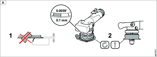
To ensure the proper formation of the radius on the workpiece end face, the tool must be fitted with the correct guide bearing.
To ensure the smooth and precise transition from the milled radius to the upper surface on the workpiece, the height of the guide plate must be set as described in the following table.
Note! In some materials, flame, plasma and laser cutting techniques can lead to hardening of the edges of the workpiece. This can result in significant deviations from the specified reference values.
Material and tensile strength | Bevel height (a) mm | Bevel width (C) mm |
|
|---|---|---|---|
Aluminium | 1.0 - 5.6 | 1.4 - 8.0 | 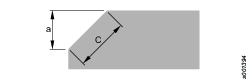 |
Steel up to 400 N/mm2 | 1.0 - 2.8 | 1.4 - 4.0 | |
Steel up to 600 N/mm2 | 1.0 - 2.1 | 1.4 - 3.0 | |
Steel up to 900 N/mm2 | 1.0 - 1.4 | 1.4 - 2.0 |
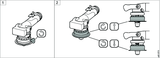
Loosen the clamping screw.
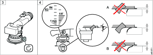
Rotate the guide plate until the required bevel height has been set.
Tighten the clamping screw.
Check by visual inspection that the cutting edge of the insert is aligned with the guide plate according to figure.
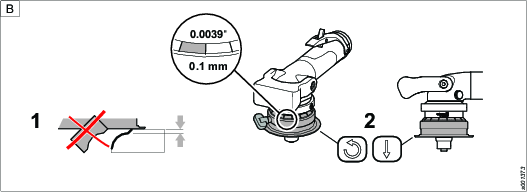
Once the bevel height has been set, a bevel should be milled on a test sample to check whether further height adjustments are required. The adjustments may be necessary because the precision of the main scale is approximately ± 1 mm.
For additional height adjustments, see figure A and B below.
Each grade on the scale indicates 0.1 mm.