STRwrench QA Inspector Software (10.01x)
Software
Introduction
In this section, you can find the basic information about the product and also the formatting conventions used in the topics.
General Data Protection Regulation (GDPR)
This product offers the possibility to process personal identifiable information such as system user name, role and IP-address. The purpose of this processing capability could be to enhance quality control through traceability and proper access management.
If you decide to process personal data you need to be aware of and comply with relevant personal data protection rules, including, in the EU the GDPR as well as other applicable laws, directives and regulations. Atlas Copco can in no way be held liable for any use made by you of the product.
Liabilities and Warnings
Liability
Many events in the operating environment may affect the tightening process and shall require a validation of results. In compliance with applicable standards and/or regulations, we hereby require you to check the installed torque and rotational direction after any event that can influence the tightening result. Examples of such events include but are not limited to:
initial installation of the tooling system
change of part batch, bolt, screw batch, tool, software, configuration or environment
change of air- or electrical connections
change in line ergonomics, process, quality procedures or practices
changing of operator
any other change that influences the result of the tightening process
The check should:
Ensure that the joint conditions have not changed due to events of influence.
Be done after initial installation, maintenance or repair of the equipment.
Occur at least once per shift or at another suitable frequency.
Safety Signal Words
The safety signal words Danger, Warning, Caution, and Notice have the following meanings:
DANGER | DANGER indicates a hazardous situation which, if not avoided, will result in death or serious injury. |
WARNING | WARNING indicates a hazardous situation which, if not avoided, could result in death or serious injury. |
CAUTION | CAUTION, used with the safety alert symbol, indicates a hazardous situation which, if not avoided, could result in minor or moderate injury. |
NOTICE | NOTICE is used to address practices not related to personal injury. |
About the User Guide
This user guide describes how to configure and operate the STRwrench using STRwrench QA Inspector Software through the STRwrench Controller EHMI or via STRwrench Web User Interface.
Target group
This user guide is intended for anyone configuring or operating an STRwrench using STRwrench QA Inspector Software.
Revision History
Release number | Revision date | Revision description |
|---|---|---|
10.01x | 06-2025 | New content: Updated content:
|
10.00x | 05-2025 | New content:
Updated content: |
09.01x | 11-2023 | New content:
Updated content:
|
09.00x | 08-2023 |
|
Conventions
To enhance user understanding, certain formatting conventions are used throughout this document. The formatting conventions used are listed below.
Element | Notation | Description | Output |
|---|---|---|---|
General emphasis | In the Program workspace. | To make certain text elements stand out, or to highlight. | Text in Bold |
Graphical User Interface (GUI) items | Select the Function button. | Any reference to items found on screen in the GUI (for example, command buttons, icon names and field names). | Text in Bold |
Graphical User Interface (GUI) Path > | Generally, on the top of the GUI. | Navigation aid which keeps track of the location in the GUI. | For example: Controller > Program > Edit |
User input | Enter a Description for the program. | Any text input by the user. | Text in Bold |
File names | Enter a File Name for the export. | Files either exported from, or imported into the system. | Text in Bold Italic |
Variable and parameter names | Enter a Name for the export. | Variable and parameter names (not values). | Text in Italic |
Variable and parameter values | Enter a VALUE for the export. | Variable and parameter values. | Text in BOLD CAPS |
System output | Client.Domain.Models.ExportImportConfiguration | Any text output by the system. | Text in Monospace |
External links | Links to external sites that have information connected to the document or subject content. These could include:
| Selectable text to external sites | |
Internal documentation links |
If available, these links will be presented below the text. | Selectable text to internal content |
The User Interface
Main menu
The main menu contains the following items:
Menu item | Description |
|---|---|
| Route
Available only on the STRwrench Controller EHMI. |
| Joints
|
| Quick programming Available only on the STRwrench Controller EHMI. |
| Results
|
| Integrated Controller Tool
|
| Configuration
|
| Isolated mode Available only on the STRwrench Controller EHMI. |
| Power |


Icons
The following table gives an overview of the icons and buttons available on the user interface:
Icon | Name | Description |
|---|---|---|
| Apply | Apply settings / changes. |
| Add | Add item. |
| Edit | Edit item. |
| Delete | Delete item(s). |
| Close | Close a function or a view. |
| Search | Search an item. |
| Run | Run a route / an inspection. |
| Skip | Skip measurement / inspection in a route. |
| Skip tag | Skip request for traceability tag during a test. |
| Skip measurement / inspection | Skip measurement / inspection in a route. |
| Reset | Reset route. |
| Back | Move to the previous view. |
| Next | Move to the next view. |
| Full-screen | Open the plot in full-screen mode. |
| Zoom reset | Exit the zoom-in view. |
| Plot type | Select plot type. |
| Info | View information. |
| Save | Save item locally. |
| Calendar | Select date. |
| Time | Select time. |
| Language | Select language. |
| Wireless connection ON | Wireless connection active. |
| Wireless connection OFF | Wireless connection absent. |
| ToolsNet connection ON | ToolsNet connection enabled and active. |
| ToolsNet connection OFF | ToolsNet connection enabled but absent. |
| Battery level | Battery level indicator. |
| API connection ON | API connection enabled and active. |
| Open Protocol connection ON | Open Protocol connection enabled and active. |


If the icons for API, Open Protocol, and ToolsNet are not enabled for EHMI, there is a blank space where these icons appears. This indicates that these features are currently unavailable or not activated in the system.
Installation and Upgrade
In this section, you can find information to help with the initial installation of the product, or upgrading from one version to another.
Prerequisites
To import and run routes on STRwrench QA Inspector Software, a licensed version of QA Supervisor 09.00x or later is required.
For more information, refer to QA Supervisor Configuration Manual and QA Supervisor Installation and Upgrade Manual.
Web Browser Requirements
The following web browsers are recommended for the STRwrench QA Inspector Software web user interface:
Firefox (latest version).
Google Chrome (latest version).
Microsoft Edge (latest version).
Upgrading
Software Versions
Two software versions can be installed in the STRwrench simultaneously. Installing a second version of the software is useful when performing upgrades on multiple devices. When production is ready for switching to the upgraded software, the new version is activated via STRwrench QA Inspector Software.
Changing software version does not automatically transfer the device configurations or stored data.
Updating Software Version
During the software update, the connection between the device and the STRwrench QA Inspector Software web user interface must be via USB cable.
The software update cannot be performed if the device is in measuring mode. To proceed with the software update, if you are in measuring mode go back to the STRwrench EHMI home menu. For more information on how to exit the measuring mode, refer to Exiting the Measuring Mode.
Connect the STRwrench to the computer via USB cable.
Access the STRwrench QA Inspector Software web user interface.
On the web user interface sidebar menu, select Integrated Controller Tool
 .
.On the Integrated Controller Tool page, select the Software tab.
Under Software update, click Choose file.
Alternatively, drag and drop the zip file with the applicable software version directly into the dedicated field.Browse and select the zip file with the applicable software version.
Under Software update, click Update software.
In the confirmation dialog, click Yes.
The operation might take several minutes.
The device is automatically restarted for the update to take effect.
Activating the Stored Software Version
During the software update, the connection between the device and the STRwrench QA Inspector Software web user interface must be via USB cable.
The software update cannot be performed if the device is in measuring mode. To proceed with the software update, if you are in measuring mode go back to the STRwrench EHMI home menu. For more information on how to leave the measuring mode, refer to Exiting the Measuring Mode.
Connect the STRwrench to the computer via USB cable.
Access the STRwrench QA Inspector Software web user interface.
On the web user interface sidebar menu, select Integrated Controller Tool
.On the Integrated Controller Tool page, select the Software tab.
Under Stored version, click Revert to this version.
In the confirmation dialog, click Yes.
The operation might take several minutes.
The device is automatically restarted for the activation to take effect.
Changing software version does not automatically transfer the device configurations or stored data.
Licenses
Viewing Available Licenses
On the web user interface sidebar menu, select Integrated Controller Tool
.On the top bar of the Integrated Controller Tool page, select the Licenses tab.
The Licenses tab lists the available licenses and their Status, which can be either Active or Not Active.
The available licenses are:
STRwrench Advanced Joint Check (official license).
STpad Joint Check (compatible license).
Activating a License
During this operation, the connection between the device and the STRwrench QA Inspector Software web user interface must be via USB cable.
Connect the STRwrench to the computer via USB cable.
Access the STRwrench QA Inspector Software web user interface.
On the web user interface sidebar menu, select Integrated Controller Tool
.On the Integrated Controller Tool page, select the Licenses tab.
In the upper-right corner of the Licenses tab, click Add.
Under Step 1 - Generate Capability Request, enter in the dedicated field the activation code you have been given. Then, click Generate to download the Capability Request file.
Go to the License Activation Portal at https://atlascopco.flexnetoperations.com and upload the Capability Request file to download the Capability Response file.
Under Step 3 - Upload the Capability Response, click Choose file to browse and upload the Capability Response file.
The activated license is displayed in the Licenses list with Status set as Active.
Configuration
In this section, you can find detailed information about how to create, modify, and verify product settings.
Getting Started
Logging in
In the Username field, enter the username.
In the Password field, enter the password.
Select Login.
At the first login, type the default login credentials:
Username: admin
Password: admin
Selecting the Language
On the Login page, select Language
 .
.Select a language from the available ones:
German.
English.
Italian.
French.
Swedish.
Czech.
Spanish.
Hungarian.
Chinese.
Japanese.
Polish.
Portuguese.
Rumanian.
Slovak.
Turkish.
Accessing the Web User Interface
Remove the cover of the tool's USB connection port.
Connect the tool to the USB-port of the PC.
Open a web browser and type in the IP address 169.254.1.1.
To access the web user interface wirelessly, refer to the instructions in the section Configuring a Wireless Client.
Working with the EHMI
Users
On the left-side menu bar, click Main Data > Users.
A | Users workspace | B | Command buttons |
The Users workspace is divided into the following columns:
User: user name of the user.
Name: Name of the user.
Role: Role of the user
In the Users workspace, click a user to display the related User Details card.
On the upper-right corner of the User Details card, click the Close(<) button to exit the User Details card (without saving changes).
On the upper-right corner of the Users workspace, there are the following command buttons:
Add: click to add a new user into the Users workspace.
Select: click to select and delete a required User(s).
Adding a User
On the home menu, tap Configuration.
On the Configuration page, tap Main Data.
Tap User.
On the upper-right corner of the User page, tap Add button to add new user.
In General category of the Add user page, configure the following parameters:
Username: enter the user name. This name will be used for the login.
Password: enter the password used for the login of the user.
Confirm password: enter again the password.
If the string entered in the Password text box and Confirm password text box are different, the Confirm password text box is red highlighted.
First name: enter the name of the user.
Last name: enter the last name of the user.
Has password: select the check box to require the password at the user login.

If the Has password check box is not selected, at the Login the user must leave empty the password text box. This case is useful to have the traceability of the results without the password request at the login.
Assign User Role:
Role: Select the role for the user profile.
The user role defines the authorization given to user. All users can use the system.
The admin user can:
Configure general settings (described in “General Settings” section).
Configure external systems (described in “External systems” section).
Configure Users (described in the “Users” section).
Configure maintenance operations (described in the “Maintenance” section).
Configure Network setting (described in the “Network Setting” section).
These menus are disabled for the operator user.
User Enabled: select the checkbox to enable the user profile.
If the user profile is disabled, the account cannot access the device.
Only Admin users have access to General Settings, External Systems, Users, Maintenance sections.
On the upper-right corner of the Add user page, tap the Save button to add the new user.
Deleting a User
On the home menu, tap Configuration.
On the Configuration page, tap Main Data.
Tap User.
On the upper-right corner of the Users page, tap Select to select the required user(s) and tap Delete
In the Confirmation required dialog box, tap OK.
It is not possible to:
Delete the default admin profile.
Delete your own profile.
Delete the profile of other logged-in users.
Editing a User
On the home menu, tap Configuration.
On the Configuration page, tap Main Data.
Tap User.
In the Users page, tap an existing user.
In the Edit user page, edit the necessary parameter(s) according to the customer needs.
On the upper-right corner of the Edit user page, tap Save button.
It is not possible to:
Change the role or disable profiles of logged-in users.
Change the role of the default admin.
Change the 'Password' field for the default admin.
To change the default admin profile, set the recovery data.
The recovery data is used during the recovery procedure.
Route
The Route page lists the routes already stored in the device and enables the user to manage and run them.
On the home menu, tap Route.
The row of each route displays:
The Name assigned to the route when created.
The Sequence mode of the inspections to run in the Route. It can be either Free, Forced by piece or Forced by inspection.
The Route status. It can be either Completed or Not completed
Adding a Route via QA Supervisor
Routes can be sent to the STRwrench Controller from QA Supervisor.
For further information, refer to QA Supervisor Configuration Manual.
Viewing Route Information
On the home menu, tap Route.
On the Route page, tap the row of the route of interest.
The General category lists the following route information:
Parameter | Description |
|---|---|
Name | Name assigned to the route when created. |
Mode | How many times the inspection(s) must be run in the route:
|
Inspection sequence | Order in which inspections are run in the route:
|
Status | Status of the route according to the inspections that have been run so far:
|
The Inspections category lists all the inspections defined for the route.
Each row displays the following information about the single inspection:
Name of the inspection.
Inspection status:
To Do: inspection has yet to be run.
OK: inspection result is ok.
NOK: inspection result is not ok.
Searching a Route
On the home menu, tap Route.
On the top bar, tap Search
 .
.In the search text box, type the string to search.
Partial matching is supported.
Deleting a Route
On the home menu, tap Route.
On the Route page, select the checkbox of the route to delete.
On the top bar, tap Delete
 .
.In the confirmation dialog, tap OK.
Resetting a Route
On the home menu, tap Route.
On the Route page, select the checkbox of the route to reset.
On the top bar, tap Reset

By resetting a route, the status of the route turns to Not completed and it is possible to run the route again.
The results saved before the reset are not deleted.
Joints
The Joints page lists the joints stored in the device and enables the user to add joints and to configure the joint parameters required to run a test.
On the home menu, tap Joints.
In the joints list, each row displays the following information:
Name assigned to the joint when created.
Torque Target value and Tolerance defined for the joint when created.
Angle Target value and Tolerance defined for the joint when created.
Adding a Joint
On the home menu, tap Joints.
On the top bar of the Joint tab, tap Add
 .
.Edit the required joint parameters in each category.
For further information, refer to Joint Parameters.In the Inspection category, it is possible to add and configure inspections. For further information, refer to Joint Inspections.
On the top bar of the Add joint page, tap Apply
 .
.
Editing a Joint
On the home menu, tap Joints.
On the Joints page, tap the row of the joint to edit.
On the Edit joint page, edit the required joint parameters in each category.
For further information, refer to Joint Parameters.In the Inspection category, it is possible to add and edit inspections. For further information, refer to Joint Inspections.
On the top bar of the Edit joint page, tap Apply
.
Deleting a Joint
On the home menu, tap Joints.
On the Joints page, select the checkbox of the joint to delete.
On the top bar, tap Delete
.In the confirmation dialog, click OK.
Searching a Joint
On the home menu, tap Joints.
On the top bar, tap Search
.In the search text box, type the string to search.
Partial matching is supported.
Joint Inspections
There are two available Test Types for inspections:
Cp/Cpk
SPC
Adding a Joint Inspection
On the home menu, tap Joints.
On the Joints page, tap the row of the joint you want to add an inspection to.
On the Edit Joint page, expand the Inspection category and tap Add
on the top bar.In the Test type dialog box, select the inspection type from the following options:
Cp/Cpk.
SPC.
Configure the required inspection parameters in each category.
On the top bar of the Add inspection page, tap Apply
.
Editing a Joint Inspection
On the home menu, tap Joints.
On the Joints page, tap the row of the joint linked to the inspection to edit.
In the Inspections category of the Edit joint page, tap the row of the inspection to edit.
On the Edit inspection page, edit the required inspection parameters in each category.
On the top bar of the Edit inspection page, tap Apply
.
Deleting a Joint Inspection
On the home menu, tap Joints.
On the Joints page, tap the row of the joint linked to the inspection to delete.
In the Inspections category of the Edit Joint page, select the checkbox of the inspection to delete.
On the top bar, tap Delete
.In the confirmation dialog, tap OK.
Quick Programming
Quick programming is a feature that allows running an inspection with a quick configuration of the joint.
In Quick programming the user only has to select the required strategy and to define the lower and upper torque limits for the operation, while the remaining parameters are automatically filled out by the software.
The configuration of joints and inspections created with the Quick programming feature is editable. If the joint or the linked inspection are edited, they are automatically saved and the joint becomes available in the Joints page's list.
Running a Quick Programming
On the home menu, tap Quick Programming.
In the Select strategy dialog, select the strategy to use from the following options:
Residual Torque/Angle
Residual Torque/Peak
In the Select limits dialog, set the upper and lower torque limits.
The value range for both limits is 8.00 - 80.00 Nm.Tap Apply
.On the Joints page, a joint is automatically created and configured with the settings specified in the Select strategy and Select limits dialogs.
The default Test type for joints created with the Quick programming feature is Cp/Cpk.Tap Run
 to run the inspection linked to the joint.
On the top bar of the Quick programming page, tap Save  to save the joint and the inspection configured with the Quick programming feature.
Results
The Results page lists the results of the inspections that have been run and allows the user to view results details.
On the home menu, select Results.
In the results list, each row displays the following information:
Name of the performed inspection.
Date and time of the performed inspection.
Viewing Result
On the home menu, tap Results.

On the Result details page, the following result details are listed:
General category:
Information
Description
Inspection name
Name of the inspection.
Inspection type
Type of inspection:
Cp/Cpk
SPC
Strategy
Strategy applied to the inspection:
Residual Torque/Angle
Residual Torque/Peak
Residual at Angle
Minimum Torque
Minimum After Breakaway
Intersection
Pitch Change
Date
Date and time when the inspection has been run.
Inspected object
Name of the inspected object.
Status
Inspection status:
Completed - all required samples have been acquired.
Partial - the number of samples is not completed or is equal to 0.
Abandoned - the inspection/joint has been deleted or the parameters that reset the statistics have changed.
Result
Inspection result:
OK
NOK
Empty field (the inspection status is either partial or abandoned).
Measuring device
Model of measuring device used fo the inspection.
Measuring device S/N
Serial Number of the measuring device used fo the inspection.
Transducer
Model of transducer used fo the inspection.
Transducer S/N
Serial Number of the transducer used fo the inspection.
Searching Results
On the home menu, tap Results.
On the top bar, tap Search
.In the search text box, type the string to search.
Partial matching is supported.
Result Details
On the home menu, tap Results
.On the Results page, select result from the list.
It displays the general details of the selected result.
On the Result details page, tap Results that displays the list of measures.
Tap Measures to display the list details.
On the Measure page, it displays general details, trace, traceability.
On the Measure page, on the top bar tap Trace.
Trace displays the graphical representation of trace. Use the respective buttons to zoom in or change the type of trace.
On the Measure page, tap Traceability in the top bar. It displays corrective actions, assignable causes, or traceability tags.
Integrated Controller Tool
Viewing Tool Information
On the home menu, tap Integrated Controller Tool > Tool.
Tap Tool to view the following information on the measuring device:
Information | Description |
|---|---|
Model | Measuring device model denomination. |
Serial Number | Measuring device serial number. It may be needed for the correct spare parts list or for service instructions. |
Product Number | Measuring device product number. |
Tap smartHEAD to view the following information on the smartHEAD:
Information | Description |
|---|---|
Model | smartHEAD model denomination. |
Serial Number | smartHEAD serial number. It may be needed for the correct spare parts list or for service instructions. |
Maximum Torque | smartHEAD torque capacity. |
Product Number | smartHEAD product number. |
Tap TAG to view the following information on the TAG:
Information | Description |
|---|---|
TAG ID | TAG number. |
Torque Correction Coefficient | Torque correction coefficient defined for the TAG. |
Angle correction | Angle correction defined for the TAG. |
Nominal torque | Torque at which the Angle correction is defined. |
Tap Maintenance to view the following information on the transducer:
Information | Description |
|---|---|
Is transducer overloaded? | Yes - the transducer has been overloaded. |
Highest torque value | Highest torque output measured by the transducer. |
Highest torque date | Date and time when the highest torque output was measured by the transducer. |
Angle correction | Angle correction coefficient for the smartHEAD due to the wrench bending. |
Transducer calibration date (CW) | Date of the last torque calibration in clockwise direction. |
Gyro calibration date (CW) | Date of the last gyroscope calibration in clockwise direction. |
Transducer calibration date (CCW) | Date of the last torque calibration in counterclockwise direction. |
Gyro calibration date (CCW) | Date of the last gyroscope calibration in counterclockwise direction. |
Next calibration date | Date of the next calibration expiration. |
Number of measurements | Number of measurements performed by the transducer so far. |
Configuration
Network Configurations
The tool can be set up to be accessed wirelessly from a web browser on a Local Area Network (LAN), using IPv4 protocol.
Remove the cover of the tool's USB connection port.
Connect the tool to the USB-port of the PC.
Open a web browser and type in the address 169.254.1.1.
Configuring a Wireless Client
On the EHMI home menu, tap Configuration > Wireless.
In the upper-right corner of the Wireless configuration page, tap Edit
 .
.On the General tab, select Enabled.
If you want to manually configure your network device, clear the DHCP checkbox and fill out the required information as provided by the local system administrator:
IP address
Subnet mask
Gateway
Enter a Network name (SSID).
On the Security tab, select a Mode in the drop-down list:
If Disabled is selected, the wireless network will be unsecured.
If WPA2 Personal is selected, enter a Security key.
If WPA2 Enterprise is selected, enter security parameters and import cert files and keys as applicable.
Use the Web User Interface to edit the TLS and the FAST parameters.
On the Optional tab, configure settings as applicable.
Hostname: enter a hostname for the device.
Warn on signal strength below (dBm): define below which signal strength value a warning must be activated (default value: -60; value range: -100 - -0).
Roaming threshold (dBm): define below which signal strength value the device must search for another access point to attempt roaming (default value: -70; value range: -90 - -45).
Connect to hidden Wi-Fi network: select the checkbox to enable connection to a hidden Wi-Fi network.
On the top bar, tap Apply
.The device will establish a wireless connection to the network.
To access the user interface wirelessly, type the device IP address into a web browser.
Configuring Channels
On the home menu, tap Configuration > Wireless.
In the upper-right corner of the Wireless configuration page, tap Edit
.On the General tab, select Enabled.
On the Channels tab, select the channels in the drop-down lists according to the frequencies and bands.
Tap Select all to select all available channels for the band. Tap Clear all to clear all the selected channels.
On the top bar of the Wireless configuration page, tap Apply
.
Setting Date and Time
On the home menu, select Configuration > Date/Time.
In the upper-right corner of the Date/Time configuration page, tap Edit
.Configure the following parameters:
Time zone: select the time zone from the dropdown list.
Date: tap Calendar
 , select a date and tap Apply
.
, select a date and tap Apply
.Time: tap Clock
 , select a time and tap Apply
.
, select a time and tap Apply
.
On the top bar of the Date/Time configuration page, tap Apply
.
Configuring the Tool
On the home menu, tap Configuration > Tool configuration.
On the General tab, select or clear the checkboxes to configure the following features:
Feature
Description
Vibration
Selected: Vibration device behaves according to STRwrench ongoing operation.
Clear: Vibration device is always off.
Buzzer
Selected: Audio signaling device behaves according to STRwrench ongoing operation.
Clear: Audio signaling device is always off.
Front LED
Selected: Front LED lights up when the dedicated button is pressed.
Clear: Front LED is always off.
Smart zeroing
Selected: If the STRwrench detects any movement during the zero adjustment, the zeroing procedure will start over again.
Clear: If the STRwrench detects any movement during the zero adjustment, the zeroing procedure will not start over again.
Tag
Selected: Information on the Tag is displayed and can be edited in the Integrated Controller Tool > Tool menu.
Clear: Information on the Tag is not be displayed.
On the Barcode tab, select in the dropdown list a barcode mode from the following options:
Option
Description
Disabled
The selection of inspections triggered by barcode scan is disabled.
Only local
The selection of inspections triggered by barcode scan is enabled only locally on the STRwrench.
From QAS
The selection of inspections triggered by barcode scan is enabled only on QA Supervisor.
To be read by the STRwrench scanner, a barcode must contain at least three characters.
In the top bar, tap Apply
.
Configuring the Inspections Default Settings
On the home menu, select Configuration > Preferences > Inspections default.
On the General tab, in the dropdown list select the default Torque unit of measurement for inspections:
Unit of measurement
Description
Nm
Newton meter
dNm
deci Newton meter
kgf.m
kilogram-force meter
kgf.cm
kilogram-force centimeter
lbf.ft
pound-force foot
lbf.in
pound-force inch
ozf.ft
ounce-force foot
ozf.in
ounce-force inch
kpm
kilopond meter
On the top bar, tap Apply
.
Configuring the Users Settings
On the home menu, select Configuration > Preferences > Users.
On the General tab, select or clear Enable login to respectively turn on or turn off the login credentials request when accessing STRwrench QA Inspector Software on the controller EHMI.
On the top bar, tap Apply
.
Login cannot be disabled on the STRwrench QA Inspector Software Web User Interface even if it is disabled on the EHMI.
External Systems
Configuring the API Communication
When installing or upgrading QA Inspector, the application runs an automatic check to determine whether the API communication must be enabled by default:
If QA Inspector detects previous connections to external systems or applications via API, the API communication is enabled by default. This is the case of QA Inspector upgrades in which the database of the previous version is kept through the upgrade.
If QA Inspector does not detect previous connections to external systems or applications via API, the API communication is disabled by default. This is the case of QA Inspector first installations, or of QA Inspector upgrades in which the database of the previous version has been deleted.
On the home menu, tap Configuration > External systems > API.
On the General tab, select Enabled.
Enter the API Port in the text field (default value: 60005; value range: 1 - 65535).
On the top bar, tap Apply
.
Configuring the ToolsNet Connection
On the home menu, tap Configuration > External systems > ToolsNet.
On the General tab, select Enabled.
On the PIM tab, enter the following parameters:
Parameter
Description
Address
Enter ToolsNet server IP address.
Port
Enter ToolsNet server port.
Range value: 1 - 65535; default value: 9014.
On the Configuration tab, enter the following parameters:
Parameter
Description
Station number
Enter the number that ToolsNet must associate to the results collected by STRwrench.
Range value: 1 - 9999.
Station name
Enter the name that identifies STRwrench in ToolsNet tree structure.
Send traces
Select the checkbox to enable STRwrench to send traces to ToolsNet
On the top bar, tap Apply
.
For further information on how to use ToolsNet 8, refer to ToolsNet 8 User Guide.
Configuring the Open Protocol
On the home menu, tap Configuration
 .
.On the Configuration page, tap External Systems.
On the External Systems page, tap Open Protocol.
On the Open Protocol page, configure the fields and tap Save.
If the device is successfully connected with Open Protocol, it shows a connected icon.
OPC UA
On the Home page, tap Configuration > External systems > OPC UA.
To enable the OPC UA protocol, select the Enabled check box and enter the port number to use in the OPC UA Port field. Then, tap Save.
Default value: 4840
By default, the Enabled checkbox is not selected.
When the OPC UA is connected, it will show a connection icon ( ) on 5th position of EHMI.
Performing a Factory Reset
On the home menu, select Configuration > Reset.
On the Reset page, tap Factory reset controller.
In the confirmation dialog, tap YES.
The STRwrench will automatically restart to complete the Factory Reset.
After the Factory Reset is completed, all settings, configurations and stored data will be deleted.
Isolated Mode
On the home menu, tap Isolated Mode.
Apply torque and angle.
The screen displays the torque and angle results in real time.
Working with the Web User Interface
Joint and Inspections Configuration
The Joints page lists the joints stored in the device and enable the user to add joints and to configure the joint parameters required to run the test.
Managing and Configuring Joints
On the sidebar menu, tap Joints.
On the Joints page, search for created joints in search bar.
To create new joints, tap Add button.
To delete the joints tap the checkbox to select the joint from list and tap Delete button.
To view and edit joint configuration data, tap the joint from list.
Managing and Configuring Joint Inspections
On the Joints page, tap the joint from list to view inspection list.
To create new inspections, tap Add button.
To delete the created inspections tap the checkbox to select the inspection from list and tap Delete button.
To view and edit joint inspection configuration data, tap the joint inspection from list.
Inserting Images in Joint Inspections
In inspection configuration, under Picture, tap Select and select an image from the system.
The inspection image is shown when executing the inspection.
Results
The Results page lists the results of the inspections that have been run.
On the sidebar menu, select Results .
Below are the columns that define the list of results:
Inspection: name of the performed inspection.
Inspected object: name of the inspected object.
Date: date and time when the inspection has been run.
Status: status of the inspection. Depending on the selected inspection, the status can be one of the following options:
Partial: the number of samples is not completed or is equal to 0.
Completed: all required samples have been acquired.
Abandoned: the inspection/joint has been deleted or the parameters that reset the statistics have changed.
Result: the result of the inspection can be:
OK.
NOK.
Empty field: the inspection status is either partial or abandoned.
If the inspection type is SPC, no result is displayed until the ongoing subgroup is completed.
Viewing Result Details
In the sidebar menu, tap Results
.On the Result page, click the row for the desired result.
On the Result details page, the following result details are displayed:
General
Information | Description |
|---|---|
Inspection name | Name of the inspection. |
Inspection type | Type of inspection:
|
Strategy | Strategy applied to the inspection:
|
Date | Date and time when the inspection has been run. |
Inspected object | Name of the inspected object |
Status | Inspection status:
|
Result | Inspection result:
|
Measuring device
Information | Description |
|---|---|
Measuring device | STRwrench |
Measuring device S/N | Serial Number of the measuring device used for the inspection |
Transducer | Model of transducer used for the inspection |
Transducer S/N | Serial Number of the transducer used for the inspection |
Searching Results
On the sidebar menu, select Results
.In the search text box, type the string to search.
Partial matching is supported.
Export list of results
On the sidebar menu, tap Results
.On the Results page, tap Export on the top right corner.
A confirmation pop-up appears, tap OK.
Viewing Measure details
In the sidebar menu, tap Results
.On the Results details page, click the row for the desired measure.
On the Measure details page, it displays General details, Trace, Traceability..
On the Measure details page, tap Trace in the top bar.
Trace displays the graphical representation of trace. Use the available buttons to zoom in or change the type of trace.
On the Measure page, tap Traceability in the top bar . It displays corrective actions, assignable causes, or traceability tags.
Export result details
On the Results page, select result to display Result Details page.
On the Result Details page, tap Download.
Integrated Controller Tool
Viewing Tool Information
On the sidebar menu, select Integrated Controller Tool
.On the top bar of the Integrated Controller Tool page, select the Tool tab.
The Tool category lists the following information on the measuring device:
Information | Description |
|---|---|
Model | Measuring device model denomination. |
Serial Number | Measuring device serial number. It may be needed for the correct spare parts list or for service instructions. |
Product Number | Measuring device product number. |
The smartHEAd category lists the following information on the smartHEAD:
Information | Description |
|---|---|
Model | smartHEAD model denomination. |
Serial Number | smartHEAD serial number. It may be needed for the correct spare parts list or for service instructions. |
Maximum Torque | smartHEAD torque capacity. |
Product Number | smartHEAD product number. |
Tap TAG to view the following information on the TAG:
Information | Description |
|---|---|
TAG ID | TAG number. |
Torque Correction Coefficient | Torque correction coefficient defined for the TAG. |
Angle correction | Angle correction defined for the TAG. |
Nominal torque | Torque at which the Angle correction is defined. |
The Maintenance category lists the following information on the transducer:
Information | Description |
|---|---|
Is transducer overloaded? | Yes - the transducer has been overloaded. |
Highest torque value | Highest torque output measured by the transducer. |
Highest torque date | Date and time when the highest torque output was measured by the transducer. |
Angle correction | Angle correction coefficient for the smartHEAD due to the wrench bending. |
Transducer calibration date (CW) | Date of the last torque calibration in clockwise direction. |
Gyro calibration date (CW) | Date of the last gyroscope calibration in clockwise direction. |
Transducer calibration date (CCW) | Date of the last torque calibration in counterclockwise direction. |
Gyro calibration date (CCW) | Date of the last gyroscope calibration in counterclockwise direction. |
Next calibration date | Date of the next calibration expiration. |
Number of measurements | Number of measurements performed by the transducer so far. |
Viewing Software Information
On the sidebar menu, select Integrated Controller Tool
.On the top bar of the Integrated Controller Tool page, select the Software tab.
The Current version category lists the following information on the firmware version currently installed.
Information | Description |
|---|---|
Version | Software version number. |
Build date | Build date of the software version. |
The Stored version category lists the following information on the stored software version.
Information | Description |
|---|---|
Version | Software version number. |
Build date | Build date of the software version. |
For more information on how to update software version, refer to Updating Software Version.
For more information on how to activate the stored software version, refer to Activating the Stored Software Version.
Configuration
Configuring the Tool
On the sidebar menu, select Configuration
.On the Configuration page top bar, select the Tool configuration tab.
In the upper-right corner of the Tool configuration tab, select Edit.
Under General, select or clear the checkboxes to configure the following features:
Feature
Description
Vibration
Selected: Vibration device behaves according to STRwrench ongoing operation.
Clear: Vibration device is always off.
Buzzer
Selected: Audio signaling device behaves according to STRwrench ongoing operation.
Clear: Audio signaling device is always off.
Front LED
Selected: Front LED lights up when the dedicated button is pressed.
Clear: Front LED is always off.
Smart zeroing
Selected: If the STRwrench detects any movement during the zero adjustment, the zeroing procedure will start over again.
Clear: If the STRwrench detects any movement during the zero adjustment, the zeroing procedure will not start over again.
Tag
Selected: Information on the TAG is displayed and can be edited in the Integrated Controller Tool > Tool menu.
Clear: Information on the TAG will not be displayed.
Under Barcode, select in the drop-down list a barcode mode from the following options:
Option
Description
Disabled
The search of inspections triggered by barcode scan is disabled.
Only local
The search of inspections triggered by barcode scan is enabled only locally on the STRwrench.
From QAS
The search of inspections triggered by barcode scan is enabled only on QA Supervisor.
To be read by the STRwrench scanner, a barcode must contain at least three characters.
In the upper right corner of the Tool configuration tab, select Apply.
Network Configurations
The tool can be set up to be accessed wirelessly from a web browser on a Local Area Network (LAN), using IPv4 protocol.
Remove the cover of the tool's USB connection port.
Connect the tool to the USB-port of the PC.
Open a web browser and type in the address 169.254.1.1.
Configuring a Wireless Client
On the sidebar menu, select Configuration
.On the Configuration page top bar, select the Network tab.
In the upper-right corner of the Network tab, select Edit.
Under General, select Enabled.
If you want to manually configure your network device, clear the DHCP checkbox and fill out the required information as provided by the local system administrator:
IP address
Subnet mask
Gateway
Enter a Network name (SSID).
Under Security, select a Mode in the dropdown list:
If Disabled is selected, the wireless network will be unsecured.
If WPA2 Personal is selected, enter a Security key.
If WPA2 Enterprise is selected, enter security parameters and import cert files and keys as applicable.
Under Optional, edit the optional settings as applicable:
Hostname: type a hostname for the device.
Warn on signal strength below (dBm): define below which signal strength value a warning must be activated (default value: -60; value range: -100 - -0).
Roaming threshold (dBm): define below which signal strength value the device must search for another access point to attempt roaming (default value: -70; value range: -90 - -45).
Connect to hidden WI-Fi network: select the checkbox to enable connection to a hidden Wi-Fi network.
In the upper-right corner of the Network tab, select Apply.
The device will establish a wireless connection to the network.
To access the user interface wirelessly, type the device IP address into a web browser.
Configuring Channel
On the sidebar menu, select Configuration
.On the Configuration page top bar, select the Network tab.
In the upper-right corner of the Network tab, select Edit.
Under General, select Enabled.
Under Channels, select the channels in the dropdown lists according to frequencies and bands.
Click Select all to select all available channels for the band. Click Clear all to clear all the selected channels.
In the upper-right corner of the Network tab, select Apply.
Configuring the Inspections Default Settings
In the sidebar navigation menu, select Configuration
.In the Configuration page top bar, select Preference > Inspections default.
In the upper right corner of the Inspections default tab, select Edit.
In the General category, select the default Torque unit of measurement for inspections from the drop-down list:
Unit of measurement
Description
Nm
Newton meter
dNm
deci Newton meter
kgf.m
kilogram-force meter
kgf.cm
kilogram-force centimeter
lbf.ft
pound-force foot
lbf.in
pound-force inch
ozf.ft
ounce-force foot
ozf.in
ounce-force inch
kpm
kilopond meter
In the upper right corner, select Apply.
Configuring the Users Settings
In the sidebar navigation menu, select Configuration
.In the Configuration page top bar, select Preference > Users.
In the upper right corner of the Users tab, select Edit.
In the General category, select or clear the checkbox next to Enable login to respectively enable or disable the login credentials request when accessing STRwrench QA Inspector Software on the controller EHMI.
In the upper right corner, select Apply.
The login credentials request can be disabled only on the EHMI.
Setting Date and Time
On the sidebar menu, select Configuration
.On the Configuration page top bar, select Maintenance > Date/Time configuration.
In the upper-right corner of the Date/Time configuration tab, select Edit.
Under Date/Time, set the following parameters:
Time zone: select the time zone in the dropdown list.
Date: click Calendar
and select a date.Time: click Clock
and select a time.
In the upper-right corner of the Date/Time Configuration tab, select Apply.
Backing up the Data
On the sidebar menu, tap Configuration
.On the Configuration page, tap Maintenance tab, tap Backup/Restore tab.
Under Backup, tap Download to download backup data.
A pop-up shows the progress of backup.
Tap OK to complete the backup.
A backup "*.zip" file is created.
Restoring the Backup
On the sidebar menu, tap Configuration
.On the Configuration page, tap Maintenance tab, tap Backup/Restore tab.
Under Restore file, select the backup "*.zip" file.
Tap Start button.
A confirmation pop-up is shown.
In the confirmation pop-up, click OK.
Wait for the device to restart automatically.
After "Restore completed" is shown on the device screen, manually restart the device.
External Systems
Configuring the API Communication
When installing or upgrading QA Inspector, the application runs an automatic check to determine whether the API communication must be enabled by default:
If QA Inspector detects previous connections to external systems or applications via API, the API communication is enabled by default. This is the case of QA Inspector upgrades in which the database of the previous version is kept through the upgrade.
If QA Inspector does not detect previous connections to external systems or applications via API, the API communication is disabled by default. This is the case of QA Inspector first installations, or of QA Inspector upgrades in which the database of the previous version has been deleted.
On the sidebar menu, select Configuration
.On the Configuration page top bar, select External Systems > API.
In the upper-right corner of the API tab, select Edit.
Under General, select Enabled.
Enter the API Port in the text field. Alternatively, use the up and down arrow in the text field to respectively increase or decrease the value (default value: 60005; value range: 1-65535).
In the upper-right corner of the API tab, select Apply.
Configuring the ToolsNet Connection
On the sidebar menu, select Configuration
.On the Configuration page top bar, select External Systems > ToolsNet.
In the upper-right corner of the ToolsNet tab, select Edit.
Under General, select Enabled.
Under PIM, enter the following parameters:
Parameter
Description
Address
Enter ToolsNet server IP address.
Port
Enter ToolsNet server port.
Default value: 9014; value range: 1 - 65535.
Under Configuration, enter the following parameters:
Parameter
Description
Station number
Enter the number that ToolsNet must associate to the results collected by STRwrench.
Value range: 1 - 9999.
Station name
Enter the name that identifies STRwrench in ToolsNet tree structure.
Send traces
Select the checkbox to enable the device to send traces to ToolsNet
In the upper-right corner, select Apply.
For further information on how to use ToolsNet 8, refer to ToolsNet 8 User Guide.
Configuring the Open Protocol
On the sidebar menu, tap Configuration
.On the Configuration page, tap External Systems tab, tap Open Protocol tab.
On the Open Protocol page, tap Edit to configure the fields.
OPC UA
On the Home page, tap Configuration > External systems > OPC UA.
To enable the OPC UA protocol, tap OPC UA tab, then tap Edit.
Select Enabled check box and enter the port number to use in the OPC UA Port field. Then, tap Apply.
Default value: 4840
By default, the Enabled checkbox is not selected.
Exporting the Application Logs
On the sidebar menu, select Configuration
.On the Configuration page top bar, select Maintenance > Log export.
Under Log export, click Download to locally save a zipped file containing the application logs.
Import Inspections from File
The STRwrench Advanced system allows users to import joint inspection data in the form of excel. This process includes downloading the excel, entering the required data, exporting the completed file, and importing it into the system.
On the sidebar menu, tap Configuration
.On the top bar, tap Import.
On the Import page, tap Download to download the excel template.
Filling Excel Template
Open the excel template.
Enter the mandatory fields for joints and inspection data.
Make sure that the row filled out has the column "Wrong field" marked in green.
Click on the button Sort and export.
The new file named "STpad_JointInspectionImportFile.stpad" is created.
Importing Data to STRwrench Advanced
On the sidebar menu, tap Configuration
.On the top bar, tap Import.
On the Import page, tap Import File and select "*.stpad" file.
Check that the Start button for the import procedure is enabled.
Tap Start to begin the import procedure.
A confirmation pop-up appears, tap OK.
All joints are reset and replaced with new ones.
Performing a Factory Reset
On the sidebar menu, select Configuration
.On the Configuration page top bar, select Reset.
Under Factory Reset Controller, select Reset.
In the confirmation dialog, click YES.
The STRwrench will automatically restart to complete the Factory Reset.
After the Factory Reset is completed, all settings, configurations and stored data will be deleted.
Operation
In this section, you can find step-by-step information about how to operate the product.
Running a Joint Inspection
On the EHMI home menu, tap Joint.
On the row of the joint of interest, tap Run
.If the selected joint is linked to more than one inspection, a dialog listing all the linked inspections will open. Tap the desired inspection from the list to select it.
Perform the test.
Running a Free Route
Attach the required tool to the controller.
Send the required route(s) with Free sequence to the STRwrench controller.
For further information, refer to Adding a Route via QA Supervisor.On the EHMI home menu, tap Route.
On the Route page, tap the route name or tap Run
.In the Inspections category of the Edit Route page, on the row of the inspection to run, tap Run
.
In case of tests configured with traceability tags, the tags are requested during the test through dialogs that are displayed on the EHMI according to the tags' configuration.
If a traceability tag is configured as optional, it is possible to skip the tag request by tapping Skip tag  .
.
Fore more information, refer to Traceability Tags.
Running a Forced by Piece Route
Attach the required tool to the controller.
Send the required route(s) with Forced by piece sequence to the STRwrench controller.
For further information, refer to Adding a Route via QA Supervisor.On the EHMI home menu, tap Route.
On the Route page, tap the route name or tap Run
.In the Inspections category of the Edit Route page, on the row of the inspection to run, tap Run
.
In case of tests configured with traceability tags, the tags are requested during the test through dialogs that are displayed on the EHMI according to the tags' configuration.
If a traceability tag is configured as optional, it is possible to skip the tag request by tapping Skip tag .
Fore more information, refer to Traceability Tags.
If the route has been configured with the Skip option enabled and the tag's Collection Point is set to Before, it is also possible to skip the whole measurement by tapping Skip measurement / inspection  . Note that if a measurement of a forced by piece route is skipped, it is not possible to run it later.
Navigating a Forced by Piece Route
In the measurement screen of a forced by piece route, it is possible to navigate the route's inspections.
To move to the previous or to the next inspections, tap respectively Back  or Next
 .
.
To return to the inspection that is currently running, tap Run .
To skip a measurement (when applicable), you can:
select the Summary category and tap Skip

or
tap Skip
in the Inspections category of the Edit Route page.
If a measurement of a forced by piece route is skipped, it is not possible to run it later.
Running a Forced by Inspection Route
Attach the required tool to the controller.
Send the required route(s) with Forced by inspection sequence to the STRwrench controller.
For further information, refer to Adding a Route via QA Supervisor.On the EHMI home menu, tap Route.
On the Route page, tap the route name or tap Run
.In the Inspections category of the Edit Route page, on the row of the inspection to run, tap Run
.
In case of tests configured with traceability tags, the tags are requested during the test through dialogs that are displayed on the EHMI according to the tags' configuration.
If a traceability tag is configured as optional, it is possible to skip the tag request by tapping Skip tag .
Fore more information, refer to Traceability Tags.
If the route has been configured with the Skip option enabled and the tag's Collection Point is set to Before, it is also possible to skip the whole inspection by tapping Skip measurement / inspection . Note that if an inspection of a forced by inspection route is skipped, it is not possible to run it later.
Navigating a Forced by Inspection Route
In the measurement screen of a forced by inspection route, it is possible to navigate its inspections.
To move to the previous or to the next inspections, tap respectively Back or Next
.
To return to the inspection that is currently running, tap Run .
To skip an inspection (when applicable), you can:
select the Summary category and tap Skip
or
tap Skip
in the Inspections category of the Edit Route page.
If an inspection of a forced by inspection route is skipped, it is not possible to run it later.
Navigating the Measuring Mode
When running an inspection, the STRwrench Controller EHMI automatically enters measuring mode.
The measuring mode opening screen provides the following information on the ongoing inspection:
Torque limits: lower and upper torque limits values defined for the inspection.
Joint: name of the joint linked to the inspection.
Inspection: inspection type.
In the upper right corner of the screen, tap Close  to close the opening screen and view information, results and traces related to the ongoing inspection, which are updated in real time and organized in four categories:
Summary.
Chart.
Results.
Trace.
To navigate the different categories, flick left or right. Alternatively, tap on the name of the category of interest in the top navigation bar.
The bottom bar of the Measuring mode screen displays the following information:
Inspection name.
S: number of acquired samples related to the subgroup size configured for the inspection.
This item is available only for SPC inspections.B: number of times the test has been run inside the inspection.
Summary Category
The measuring mode Summary category differs according to the selected inspection type.
Summary category for Cp/Cpk
Torque limits: the lower and upper torque limits configured for the inspection.
Test Result: result of the test (OK or NOK).
Minimum Cp: value of minimum Cp configured for the inspection.
Cp: value of the Cp index calculated during the test using the measured values.
Minimum Cpk: value of minimum Cpk configured for the inspection.
Cpk: value of the Cpk index calculated during the test using the measured values.
Summary category for SPC
Torque limits: the lower and upper torque limits configured for the inspection.
X: the average value of the results of the inspection.
Range: range value according to ISO standard.
Rules: rules enabled for the inspections and their respective status:
Green mark: rule is passed.
Red mark: rule is failed.
Grey mark: number of values is not enough to assess whether the rule has been passed or not.
Tap on the Rules area of the screen to open the SPC rules check results page, and view the full description of each rule.
Tap Info  to open a page displaying the following information on the operation:
Torque limits: the lower and upper torque limits configured in the inspection.
Joint: name of the joint linked to the inspection.
Inspection: name of the inspection running.
Chart Category
The Chart category displays each value measured during the test positioned in the torque chart.
The torque chart includes the following items:
Two red lines that represent the upper and lower torque limit values configured for the inspection.
A green dashed line that represents the target torque value configured for the inspection.
Grey dots that represent the values measured during each test in the inspection.
Results Category
The Results category lists the results of the tests performed in the inspection, showing the following information:
#: sequence number of the test result inside the inspection.
Torque: measured torque value.
Angle: measured angle value.
Peak: detected torque peak value.
Angle peak: detected angle peak value.
If a test result is NOK, the result row is marked with a red bar and the NOK value is highlighted in red.
Trace Category
The Trace category shows the traces acquired for each result in the inspection.
If the Double result function is enabled, both the residual point and the peak point are shown in the plot as circles.
The Trace category provides the following functions:
Navigating the results' traces inside the inspection. To do so, tap Next
and Back
.
The result sequence number is displayed in the bottom-right corner of the screen, preceded by #:.Viewing the plot in full-screen. To do so, tap Full-screen
 .
.In full-screen mode, it is possible to select and zoom-in on a section of the curve. To do so, pinch two fingers apart on the section to zoom-in and tap on the rectangular selection that appears. To reset the plot view, tap Zoom reset
 .
.Tap Close
to exit the full-screen mode.Selecting plot type. To do so, tap Plot type
 and select the plot type to display from the following options:
Torque over Time
Angle over Time
Angle/Torque over Time
Torque over Angle
The default plot type is Torque over Angle.
Ending a Test in Measuring Mode
On the top bar of the EHMI measuring mode screen, tap More
 > End test.
In the confirmation dialog, tap Yes.
Exiting the Measuring Mode
On the top bar of the EHMI measuring mode screen, tap More
> Exit.In the confirmation dialog, tap Yes.
Deleting Results in Measuring Mode
On the Results category of the EHMI measuring mode screen, select the result to delete.
On the top bar, tap More
> Delete .
In order to remove all the collected results at once, do the following:
On the top bar, tap More
> Delete all .In the confirmation dialog, tap Yes.
Reference
In this section, you can find miscellaneous useful information.
Parameters
Joint Parameters
Parameters marked with an asterisk (*) in the user interface are mandatory.
General category
Parameter | Description |
|---|---|
Name | Type a name for the joint. |
Description | Type a description for the joint. |
Identifier | Type an identifier for the joint. |
Tightening direction | In the drop-down list, select the tightening direction for the joint:
Default value: Clockwise. |
Notes | Type additional notes for the joint. |
Torque category
Parameter | Description |
|---|---|
Unit of measurement | In the drop-down list, select the unit of measurement to use in the inspections linked to the joint from the following options:
Default value: Nm. |
Final angle monitoring torque | Type the torque value from which the angle measurement starts. The Final angle monitoring torque must be ≤ Minimum torque. Value range: 0.00 - 99999.99. Default value: 50% of the Target torque value. |
Control mode | Select the method to define the torque limits from the following options:
Default value: Target/Tolerance. |
Minimum torque | Type the lower limit value for the torque. Available only if Control mode is set to Min/Max. Value range: 0.00 - 99999.99. Default value: 0.00. |
Target torque | Type the torque target value. Available only if Control mode is set to Target/Tolerance. Value range: 0.00 - 99999.99. Default value: 0.00. |
Maximum torque | Type the upper limit value for the torque. Available only if Control mode is set to Min/Max. Value range: 0.00 - 99999.99. Default value: 0.00. |
Torque tolerance | Type the torque tolerance that defines the lower torque limit and upper torque limit according to the value specified for Target torque. Available only if Control mode is set to Target/Tolerance. Value is expressed in percentage (%). Value range: 0.00 - 100.00. Default value: 0.00. |
Angle category
Parameter | Description |
|---|---|
Control mode | Select the method to define the angle limits from the following options:
Default value: Target/Tolerance. |
Minimum angle | Type the lower limit value for the angle. Available only if Control mode is set to Min/Max. Value range: 0.00 - 9999.99. Default value: 180.0. |
Target angle | Type the angle target value. Available only if Control mode is set to Target/Tolerance. Value range: 0.00 - 9999.99. Default value: 270.0. |
Maximum angle | Type the upper limit value for the angle. Available only if Control mode is set to Min/Max. Value range: 0.00 - 9999.99. Default value: 360.0. |
Angle tolerance | Type the angle tolerance that defines the lower angle limit and the upper angle limit according to the value specified for Target angle. Available only if Control mode is set to Target/Tolerance. Value range: 0.00 - 10000.00. Default value: 90.0. |
Cp/Cpk Inspection Parameters
Parameters marked with an asterisk (*) in the user interface are mandatory.
General category
Parameter | Description |
|---|---|
Inspection name | Type a name for the inspection. |
Barcode identifier | Type an ID to identify the inspection when running a barcode scan. If left blank, the Barcode identifier corresponds to the inspection name. |
Strategy | In the drop-down list, select the inspection strategy from the following options:
Default value: Residual Torque/Angle. |
Number of samples | Type the number of results to acquire in the inspection. Value range: 0-1000. Default value: 0. |
Minimum Cp torque | Type the minimum Cp value for the inspection. The Cp index describes the process capability; it is the number of times the spread of the process fits into the tolerance width. The higher the value of Cp, the better the process. Value range: 0.00 - 9999.99. Default value: 1.67. |
Minimum Cpk torque | Type the minimum Cpk value for the inspection. The Cpk index describes the process capability corrected for position within the tolerance limits. The higher the Cpk, the more the process is centered within the tolerance limits. Value range: 0.00 - 9999.99. Default value: 1.67. |
Measuring device type | The parameter is not editable. |
Measuring device S/N | Type the serial number of the STRwrench controller. This parameter is not required. |
Transducer S/N | Type the serial number of the transducer to be used for the inspection. |
Tightening direction | In the drop-down list, select the tightening direction for the inspection:
Default value: Clockwise. |
Torque correction coefficient | Type the torque correction coefficient to be applied for the inspection. If no extension is being used, the Torque correction coefficient must be 1. Value range: 0.10 - 99.99. Default value: 1. For more information, refer to How to calculate the Torque Correction Coefficient. |
Angle correction coefficient | Type the angle correction coefficient to be applied for the inspection. If no extension is being used, the Angle correction must be 0. Value range: 0.0 - 6553.0. Default value: 0.0. For more information, refer to How to Calculate the Angle Correction. |
Open Protocol ID | Type the open protocol ID or tap on the Search icon to automatically fill the field. |
Torque category
Parameter | Description | Available with strategies: |
|---|---|---|
Cycle start | Type the torque value from which the test starts. The Cycle start must be ≤ Final angle monitoring torque. Value range: 0.00 - 99999.99. Default value: smartHEAD min load value. |
|
Final angle monitoring torque | Type the torque value from which the angle measurement starts. Value range: 0.00 - 99999.99. Default value: Cycle start value. |
|
Control mode | Select the method to define the torque limits from the following options:
Default value: Target/Tolerance. |
|
Minimum torque | Type the lower limit value for the torque. Value range: 0.00 - 99999.99. Default value: joint Minimum torque value. |
|
Target torque | Type the torque target value. Value range: 0.00 - 99999.99. Default value: joint Target torque value. |
|
Maximum torque | Type the upper limit value for the torque. Value range: 0.00 - 99999.99. Default value: joint Maximum torque value. |
|
Torque tolerance | Type the torque tolerance that defines the lower and upper torque limits according to the Target torque previously specified. Value is expressed in percentage (%). Value range: 0.00 - 100.00. Default value: joint Torque tolerance value. |
|
Minimum torque limit | Type minimum torque value that must be reached within the Angle limit value in order to get an OK result. Value range: 0.00 - 99999.99. Default value: 0.00. |
|
Maximum torque limit | Type the maximum limit value for the torque. Value range: 0.00 - 99999.99. Default value: 0.00. |
|
Change screw | Type the torque threshold to alert for a potential screw damage. The Change screw must be ≥ Maximum torque. Value range: 0.00 - 99999.99. Default value: 0.00. |
|
Angle category
Parameter | Description | Available with strategies: |
|---|---|---|
Residual angle threshold | Type the maximum angle value (measured from the Final angle monitoring torque) for the residual torque, when the residual torque is lower than the breakaway point. Value range: 0.1 - 45.0. Default value: 20.0. |
|
Breakaway angle threshold | Type the maximum angle value (measured from the Final angle monitoring torque) for the residual torque. Value range: 0.1 - 20.0 Default value: 7.0. |
|
Target angle | Type the value of the target angle: Value range: 0.0 - 9999.9. Default value: 0.0. |
|
Angle limit | Type the angle value within which the Minimum torque must be reached in order to get an OK result. Value range: 0.0 - 9999.9. Default value: 0.0. |
|
Stretch angle | Type the angle value at which the residual torque must be measured if the tightening continues after reaching the Target angle value. Value range: 0.0 - 9999.9. Default value: 0.0. |
|
Maximum angle limit | Type the value for the maximum limit angle. Value range: 0.0 - 9999.9. Default value: 0.0. |
|
Time category
Parameter | Description | Available with strategies: |
|---|---|---|
Ratchet time | Type the time-frame that defines the end of the test when the torque goes below the Cycle start value but has not reached yet the lower torque limit value The value is expressed in seconds (s). Value range: 0.1 - 30.0. Default value: 0.1. |
|
SPC Inspection Parameters
Parameters marked with an asterisk (*) in the user interface are mandatory.
General category
Parameter | Description |
|---|---|
Inspection name | Type a name for the inspection. |
Barcode identifier | Type an ID to identify the inspection when running a barcode scan. If left blank, the identifier corresponds to the inspection name. |
Strategy | In the drop-down list, select the inspection strategy from the following options:
Default value: Residual Torque/Angle. |
Number of samples | Type the number of results to acquire in the inspection. Value range: 0 - 1000. Default value: 0. |
Subgroup size | Type the number of samples that define each average value represented as a plotted point in the X-R chart. Value range: 1 - 25. Default value: 5. |
Subgroup frequency | Type the frequency of the average values analyzed and considered in the X-R chart and in the SPC rules: Value range: 1 - 999. Default value: 1. |
Measuring device type | This parameter is not editable. |
Measuring device S/N | Type the serial number of the STRwrench controller. This parameter is not required. |
Transducer S/N | Type the serial number of the transducer to be used for the inspection. |
Tightening direction | In the drop-down list, select the tightening direction for the inspection:
Default value: Clockwise. |
Torque correction coefficient | Type the torque correction coefficient to be applied for the inspection. If no extension is being used, the Torque correction coefficient must be 1. Value range: 0.10 - 99.99. Default value: 1. For more information, refer to How to calculate the Torque Correction Coefficient. |
Angle correction coefficient | Type the angle correction coefficient to be applied for the inspection. If no extension is being used, the Angle correction must be 0. Value range: 0.0 - 6553.0. Default value: 0.0. For more information, refer to How to Calculate the Angle Correction. |
Open Protocol ID | Type the open protocol ID or tap on the search icon to automatically fill the field. |
Torque category
Parameter | Description | Available with strategies: |
|---|---|---|
Cycle start | Type the torque value from which the test starts. The Cycle start must be ≤ Final angle monitoring torque. Value range: 0.00 - 99999.99. Default value: smartHEAD min load value. |
|
Final angle monitoring torque | Type the torque value from which the angle measurement starts. The Final angle monitoring torque must be ≤ Minimum torque. Value range: 0.00 - 99999.99. Default value: Cycle start value. |
|
Control mode | Select the method to define the torque limits from the following options:
Default value: Target/Tolerance. |
|
Minimum torque | Type the lower limit value for the torque. Value range: 0.00 - 99999.99. Default value: joint Minimum torque value. |
|
Target torque | Type the torque target value. Value range: 0.00 - 99999.99. Default value: joint Target torque value. |
|
Maximum torque | Type the upper limit value for the torque. Value range: 0.00 - 99999.99. Default value: joint Maximum torque value. |
|
Torque tolerance | Type the torque tolerance that defines the the lower and upper torque limits according to the Target torque previously specified. Value is expressed in percentage (%). Value range: 0.00 - 100.00. Default value: joint Torque tolerance value. |
|
Minimum torque limit | Type minimum torque value that must be reached within the Angle limit value in order to get an OK result. Value range: 0.00 - 99999.99. Default value: 0.00. |
|
Maximum torque limit | Type the maximum limit value for the torque. Value range: 0.00 - 99999.99. Default value: 0.00. |
|
Change screw | Type the torque threshold to alert for a potential screw damage. The Change screw must be ≥ Maximum torque. Value range: 0.00 - 99999.99. Default value: 0.00. |
|
Angle category
Parameter | Description | Available with strategies: |
|---|---|---|
Residual angle threshold | Type the maximum angle value (measured from the Final angle monitoring torque) for the residual torque, when the residual torque is lower than the breakaway point. Value range: 0.1 - 45.0 Default value: 20.0. |
|
Breakaway angle threshold | Type the maximum angle value (measured from the Final angle monitoring torque) for the residual torque. Value range: 0.1 - 20.0 Default value: 7.0. |
|
Target angle | Type the value of the target angle: Value range: 0.0 - 9999.9. Default value: 0.0. |
|
Angle limit | Type the angle value within which the Minimum torque must be reached in order to get an OK result. Value range: 0.0 - 9999.9. Default value: 0.0. |
|
Stretch angle | Type the angle value at which the residual torque must be measured if the tightening continues after reaching the Target angle value. Value range: 0.0 - 9999.9. Default value: 0.0. |
|
Maximum angle limit | Type the value for the maximum limit angle. Value range: 0.0 - 9999.9. Default value: 0.0. |
|
Time category
Parameter | Description | Available with strategies: |
|---|---|---|
Ratchet time | Type the time-frame that defines the end of the test when the torque goes below the Cycle start value but has not reached yet the lower torque limit value The value is expressed in seconds (s). Value range: 0.1 - 30.0. Default value: 0.1. |
|
Test Types
Cp/Cpk Test
The Cp/Cpk test assesses the capability of a process in terms of repeatability and accuracy, in order to verify whether the process meets specified requirements.
This test analyzes the process result values in relation to a tolerance range defined by an upper limit and a lower limit.
The test assessment is based on two indexes:
The Cp index describes the process capability meant as the number of times the spread of the result values fits into the tolerance range. This means the Cp index describes how close the collected result values are to one another, determining the repeatability of the process without taking into account how these values are positioned in relation to the upper and lower tolerance limits.
The Cpk index describes the process capability corrected by the position of the result values within the tolerance range. This means the Cpk index expresses how close the collected result values are to the target value (the middle of the tolerance range) determining the accuracy of the process in addition to its repeatability.

A | Upper tolerance limit | D | Cp: Low / Cpk: Low |
B | Target value | E | Cp: High / Cpk: High |
C | Lower tolerance limit | F | Cp: High / Cpk: Low |
If Cpk > 1 and Cp > 1, the process is capable and the process results are within the tolerance limits.
If Cpk < 1 and Cp < 1, the process is not potentially capable and the process results are not within the tolerance limits.
If Cpk < 1 and Cp > 1, the process is potentially capable, but it is not centered and the results are non within the tolerance limits.
SPC Test
The SPC (Statistical Process Control) test assesses wether the tightening process is under control by analyzing the trend of torque and angle values in relation to a set of control limits, according to a series of standard rules.
With an SPC test, a pre-defined number of tightening values is collected in subgroups in order to determine the average of each subgroup. The averages' trend is then analyzed to monitor its behavior in relation to the set limits, and to verify whether the SPC rules are met or not.
This test makes it possible to get a trend of the tightening process performances in order to identify beforehand critical variations that might lead to assembling faulty joints.
SPC test limits
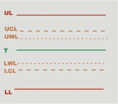
UL | Upper Limit | LWL | Lower Warning Limit |
UCL | Upper Control Limit | LCL | Lower Control Limit |
UWL | Upper Warning Limit | LL | Lower Limit |
T | Target (nominal) |
Upper Limit (UL) and Lower Limit (LL) are the limits the user configures for the test.
The other SPC test limits are calculated as follows:
Upper Control Limit = ((UL + LL) / 2) + (A · ((UL - LL) / 6)) | |
Lower Control Limit = ((UL + LL) / 2) - (A · ((UL - LL) / 6)) | |
Upper Warning Limit = ((UL + LL) / 2) + (2/3 · (UCL - ((UL + LL) / 2))) | |
Lower Warning Limit = ((UL + LL) / 2) - (2/3 · (((UL + LL) / 2) - LCL)) | |
Range = D2 · ((UL - LL) / 6 |
In these formulas, A and D2 are coefficients that depend on the number of SPC tests performed:
Number of SPC tests | A | D2 |
|---|---|---|
1 | 0.000 | 0.000 |
2 | 2.121 | 3.686 |
3 | 1.732 | 4.358 |
4 | 1.500 | 4.698 |
5 | 1.342 | 4.918 |
6 | 1.225 | 5.078 |
7 | 1.134 | 5.204 |
8 | 1.061 | 5.306 |
9 | 1.000 | 5.393 |
10 | 0.949 | 5.469 |
11 | 0.905 | 5.535 |
12 | 0.866 | 5.594 |
13 | 0.832 | 5.647 |
14 | 0.802 | 5.696 |
15 | 0.775 | 5.741 |
16 | 0.750 | 5.782 |
17 | 0.728 | 5.820 |
18 | 0.707 | 5.856 |
19 | 0.688 | 5.891 |
20 | 0.671 | 5.921 |
21 | 0.655 | 5.951 |
22 | 0.640 | 5.979 |
23 | 0.626 | 6.006 |
24 | 0.612 | 6.031 |
25 | 0.600 | 6.056 |
SPC test rules
The following rules are applied to the last set of samples collected during a single SPC test:
RULE1 - Verify whether the last average is out of control limits
| Diagnosis: The average is higher than the upper control limit, but it does not exceed the upper tolerance limit. |
| Diagnosis: The average is lower than the lower control limit, but it does not fall under the lower tolerance limit. |
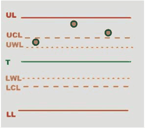

RULE 6 - Verify whether the dispersion is too large
Dispersion is considered too large when the difference between the maximum and minimum value is greater than the Range (see Range formula above).
| Diagnosis: Excessive dispersion of the values prevents a proper calibration of the tool, but the measured values are still within the tolerance limits. |
| Diagnosis: Some measured values are out of tolerance limits. Excessive dispersion of the values prevents a proper calibration of the tool. |


RULE 7 - Verify whether at least one value is outside the tolerance limits
| Diagnosis: At least one value is higher than the upper tolerance limit. |
| Diagnosis: At least one value is lower than the lower tolerance limit. |

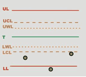
RULE 8 - Verify whether the dispersion is larger than the warning limits
| Diagnosis: Dispersion is larger than the warning limits and at least one value is outside the tolerance limits. |
| Diagnosis: Dispersion is larger than the warning limits but values are within the tolerance limits. |
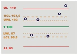

The following rules are applied to the last averages of the set of samples collected during an SPC test.
The device stores the last seven averages to analyze the trend according to these rules:
RULE 3 - Verify whether the last 7 averages are over or under the nominal value
| Diagnosis: Averages are higher than the target value, but they do not exceed the upper tolerance limit. |
| Diagnosis: Averages are lower than the target value, but they do not fall under the lower tolerance limit. |

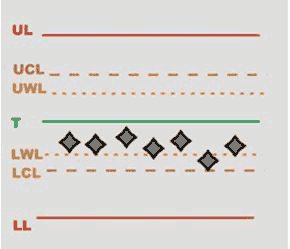
RULE 4 - Verify whether the last 7 averages are increasing or decreasing
| Diagnosis: Averages tend to be higher than the target value, but they do not exceed the upper tolerance limit. |
| Diagnosis: Averages tend to be lower than the target value, but they do not fall under the lower tolerance limit. |
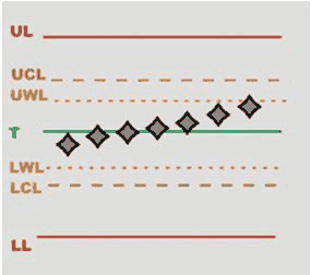

RULE 5 - Verify whether the last 2 averages out of the warning limits
| Diagnosis: Averages are higher than the Upper Warning Limit, but they do not exceed the upper tolerance limit. |
| Diagnosis: Averages are lower than the Lower Warning Limit, but they do not fall under the lower tolerance limit. |


RULE 2 - Verify whether the last 4 averages are out of 1/3 of the control limits
| Diagnosis: Averages are higher than 1/3 of the Upper Control Limit, but they do not exceed the upper tolerance limit. |
| Diagnosis: Averages are below 1/3 of the Lower Control Limit, but they do not fall under the lower tolerance limit. |
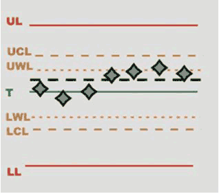

Quality Control Strategies
The aim of quality control strategies is either to check tightening operations already performed by testing the residual torque on joints, or to study joints' characteristics.
Residual Torque / Peak
This strategy evaluates the residual torque on a joint as the peak torque necessary to rotate the screw further.
Parameter | Description |
|---|---|
Inspection Name | Name of the inspection. |
Cycle start | Torque value from which the test operation starts. |
Minimum torque | Lower torque limit value. |
Maximum torque | Upper torque limit value. |
Change screw | If the torque applied reaches this limit, the message Change screw is shown on the wrench display. The Change screw must be ≥ Maximum torque. |
Target torque | Torque target value. |
Torque tolerance | Torque tolerance that defines the maximum torque and the minimum torque according to the Target torque previously specified. Value is expressed in percentage (%). |
Final angle monitoring torque | Torque value from which the angle measurement starts (usually set to 50% of the Target torque). |
Target angle | Angle target value. |
Torque units | Measurement unit set for the joint linked to the inspection. |
Control mode | Method to define the torque limits from the following options:
|
Torque correction coefficient | When extensions are used, the wrench measurement must be compensated to show a more accurate torque value. To calculate the correction coefficient, please refer to How to calculate the Torque Correction Coefficient. When extensions are not used, Torque correction coefficient = 1. |
Angle correction coefficient | When extensions cause additional wrench bending, the wrench angle measurement must be compensated to show a more accurate angle value. When extensions are not used, Angle correction coefficient = 0. |
Number of sample | Number of tests to run inside the inspection. |
Ratchet time | Starts when the torque goes below the Cycle start without reaching the 3rd percentage value. This allows the operator to release the torque for a while and recharge during the tightening operation. |
With this strategy, the breakaway point is not detected automatically. Therefore, this is a less objective method of evaluating residual torque. It may be used when the residual torque/time or torque/angle methods cannot be performed.
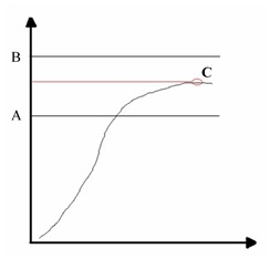
A | Minimum torque | B | Maximum torque |
C | Torque peak |
Define the torque limits to get an OK result.
If the Target angle value is not specified, the angle result is marked as Not Applicable.
If a Target angle value is specified, the residual torque result is measured at the specified angle (starting from the Final angle monitoring torque) instead of the peak torque:
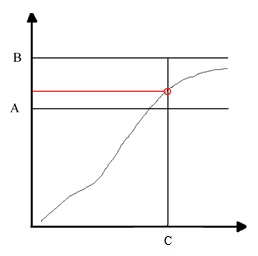
A | Minimum torque | B | Maximum torque |
C | Target angle |
During the test operation, LEDs, buzzer and vibration are activated as follows:
LED:
White LED: activated when the Cycle start is reached.
Buzzer:
The beep starts when the torque goes over the Cycle start value; the signal increases when the residual torque is detected / the tightening process has been completed.
Vibration:
Starts when the residual torque is detected if a Target angle is specified.
At the end of the test operation, LEDs, buzzer and vibration are activated as follows:
LEDs:
Green LEDs: torque result within the minimum and maximum limits.
Red LEDs: torque is outside the minimum and maximum limits range.
Buzzer
Two beeps indicate the end of the operation; if the final result is in the red area, the signal in continuous.
To stop the buzzer, start a new tightening operation or press a button on the tool controller.
Vibration:
Stays active until the torque applied is released.
Residual Torque / Angle
This strategy evaluates the residual torque on a joint, looking for the residual point of the Torque/Angle trace.
Parameter | Description |
|---|---|
Inspection Name | Name of the inspection. |
Cycle start | Torque value from which the test operation starts. |
Minimum torque | Lower torque limit. |
Maximum torque | Upper torque limit. |
Change screw | If the torque applied reaches this limit, the message Change screw is shown on the wrench display. The Change screw must be ≥ Maximum torqueMaximum torque. |
Target torque | Torque target value. |
Torque tolerance | Tolerance that defines the maximum torque and the minimum torque according to the Target torque previously specified. Value is expressed in percentage (%). |
Final angle monitoring torque | Torque value from which the angle measurement starts (usually set to 50% of the Target torque). |
Measuring unit | Measurement unit set for the joint linked to the inspection. |
Control mode | Method to define the torque limits from the following options:
|
Breakaway angle threshold | Maximum angle value (measured from the Final angle monitoring torque) for the residual torque. |
Residual angle threshold | Maximum angle value (measured from the Final angle monitoring torque) for the residual torque when the residual torque is lower than the breakaway point. |
Torque correction coefficient | When extensions are used, the wrench measurement must be compensated to show a more accurate torque value. To calculate the correction coefficient, please refer to How to calculate the Torque Correction Coefficient. When extensions are not used, Torque correction coefficient = 1. |
Angle correction coefficient | When extensions cause additional wrench bending, the wrench angle measurement must be compensated to show a more accurate angle value. When extensions are not used, Angle correction coefficient = 0. |
Number of sample | Number of tests to run inside the inspection. |
Ratchet time | Starts when the torque goes below the Cycle start without reaching the 3rd percentage value. This allows the operator to release the torque for a while and recharge during the tightening operation. |
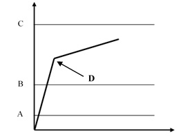
A | Cycle start | B | Minimum torque |
C | Maximum torque | D | Breakaway = Residual |
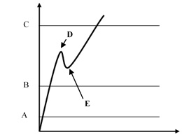
A | Cycle start | B | Minimum torque |
C | Maximum torque | D | Breakaway |
E | Residual |
Define the torque limits to get an OK result.
The Final angle monitoring torque, which must be greater than the Cycle start, defines the point from which the device algorithm starts analyzing the torque/angle trace. This is useful to filter all the noise that may occur at low torque value, and that could be detected as a false residual point.
Torque result:
If the residual point is detected, the result is associated with the residual point; the test is OK if the residual falls within the limits.
If the residual is not detected or the torque goes over the maximum torque, the torque result is the maximum value. Therefore, if the maximum value falls within the limits, the torque result is still OK, but the overall result is marked as Not OK.
If the torque goes over the Change screw value, the residual is no longer detected and the torque result is the maximum torque.
In the configuration of the Residual torque/angle strategy, there are two advanced parameters:
Breakaway angle threshold: it specifies the maximum angle for the residual torque (measured from the Final Angle Monitoring Torque).
Residual angle threshold: it specifies the maximum angle for the residual torque (measured from the Final Angle Monitoring Torque) when the residual torque is lower than the breakaway point.
If the residual point precedes the Residual angle threshold, the residual torque is detected. This is the normal condition for a residual torque test.
If the residual point is over the Residual angle threshold, the breakaway point is the result of the test. In this case, the Residual angle threshold should be increased to detect the proper residual point.
If the breakaway point is over the Breakaway angle threshold, the residual point is not detected even if the residual point precedes the Residual angle threshold.
During the test operation, LEDs, buzzer and vibration are activated as follows:
LED:
White LED: activated when the Cycle start is reached.
Buzzer:
The beep starts when the torque goes over the Cycle start value; the signal increases when the residual torque is detected / the tightening process has been completed.
Vibration:
Starts when the residual torque is detected.
At the end of the test operation, LEDs, buzzer and vibration are activated as follows:
LEDs:
Green LEDs: torque result within the minimum and maximum limits.
Red LEDs: torque is outside the minimum and maximum limits range.
Buzzer
Two beeps indicate the end of the operation; if the final result is in the red area, the signal in continuous.
To stop the buzzer, start a new tightening operation or press a button on the tool controller.
Vibration:
Stays active until the torque applied is released.
Residual Point Detection Algorithm
To detect the torque/angle residual point, the STRwrench uses an algorithm that calculates the gradient αt of the torque/angle trace by linear regression each time a new sample is collected. The algorithm then calculates the average of six different αt values:

The αaverage value is used to identify the residual point.
Algorithm application scenarios
Scenario A
When high static friction builds up into the joint (for example due to lack of lubrication), as soon as the bolt moves the torque decreases and the real residual torque is lower than the peak torque necessary to overcome the static friction. In this cases, the STRwrench algorithm monitors the αaverage: if αaverage has a negative value, the algorithm waits until the αaverage goes back to a positive value. The point in which the αaverage goes back to a positive value is considered the residual torque point.

A | Maximum torque | B | Minimum torque |
C | Final angle monitoring torque | D | Cycle start |
Scenario B
Normally, during breakaway there is a rapid change of the gradient of the torque/angle function when the bolt starts moving. The STRwrench algorithm takes as breakaway point the point of maximum distance (d) between the torque/angle trace and the straight line drawn from graph's origin to the actual point of the trace. This distance must be greater than the threshold and must be consistent for more samples.
In addition, the average slope of the part of the trace after the breakaway point must be less than 60% of the average slope of the part of the trace before the breakaway point.
If all these conditions are met, the test ends and the breakaway/residual point is detected.
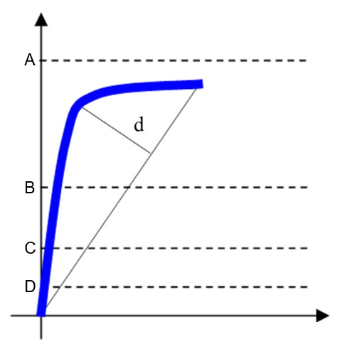
A | Maximum torque | B | Minimum torque |
C | Final angle monitoring torque | D | Cycle start |
d | Maximum distance between the trace and the straight line. | ||
Recommended settings
Cycle start | Set a value that is ≥ 2% of the smartHEAD capacity. |
Final angle monitoring torque | Set a value between Cycle start and Minimum torque. |
Minimum torque | Set the minimum residual torque value to get an OK result. |
Maximum torque | Set the maximum residual torque value to get an OK result. |
For instance, a proper setting for detecting the residual point on a bolt tightened to 50 N∙m using an STRwrench with a 80 N∙m smartHEAD could be the following:

A | Maximum torque | B | Minimum torque |
C | Final angle monitoring torque | D | Cycle start |
Three points residual
During an inspection, 3 points may appear in the trace result: Residual point, Breakaway point, and Peak point.
The overall result of the inspection is decided according to the inspection configuration.
The trace result can be set at the inspection configuration via Web User Interface or via EHMI when the strategy is "Residual Torque/Angle".
It can also be set as a default configuration at Configuration → Preferences → Inspections default → Torque/Angle.
Residual at Angle
This strategy evaluates the residual torque on a joint as the torque value measured at the angle value required for further rotation.
Parameter | Description |
|---|---|
Inspection Name | Name of the inspection. |
Cycle start | Torque value from which the test operation starts. |
Maximum torque limit | Upper torque limit value. |
Change screw | If the torque applied reaches this limit, the message Change screw is shown on the wrench display. The Change screw must be equal or higher than the Maximum torque. |
Final angle monitoring torque | Torque value from which the angle measurement starts (usually set to 50% of the Target torque). |
Target angle | Angle value at which the residual torque result is measured. |
Stretch angle | Angle value to assist the operator in keeping on tightening uniformly after the Target angle has been reached. If the Stretch angle is specified, the tightening must continue until the Stretch angle value is reached in order to get a consistent residual torque result. Stretch angle must be > Target angle and < Maximum limit angle. |
Maximum angle limit | Upper angle limit value. |
Torque units | Measurement unit set for the joint linked to the inspection. |
Torque correction coefficient | When extensions are used, the wrench measurement must be compensated to show a more accurate torque value. To calculate the correction coefficient, please refer toHow to calculate the Torque Correction Coefficient. When extensions are not used, Torque correction coefficient = 1. |
Angle correction coefficient | When extensions cause additional wrench bending, the wrench angle measurement must be compensated to show a more accurate angle value. When extensions are not used, Angle correction coefficient = 0. |
Number of sample | Number of tests to run inside the inspection. |
Ratchet time | Starts when the torque goes below the Cycle start without reaching the 3rd percentage value. This allows the operator to release the torque for a while and recharge during the tightening operation. |

A | Maximum limit torque | E | Target angle |
B | Residual torque | F | Stretch angle |
C | Final angle monitoring torque | G | Maximum limit angle |
D | Cycle start |
Torque result:
Stretch angle is not defined
If angle is between target angle and maximum limit angle -> the residual torque is the torque value measured at target angle, and the peak torque is the peak torque value.
If angle is greater than target angle maximum limit angle -> the residual torque = the peak torque = the peak torque value (not at target angle).
Stretch angle is defined
If angle is between target angle and stretch angle -> the residual torque is the torque value measured at target angle, and the peak torque is the peak torque value.
If angle is between stretch angle and maximum limit angle (Not mandatory to continue until reach to stretch angle) -> the residual torque is the torque value measured at target angle, and the peak torque is the peak torque value.
If angle is greater than target angle maximum limit angle -> the residual torque = the peak torque = the peak torque value (not at target angle).
During the test operation, LEDs, buzzer and vibration are activated as follows:
LED:
White LED: activated when the Cycle start is reached.
All white LEDs: activated when the Target angle is reached if a Stretch angle value is specified.
Buzzer:
The beep starts when the torque goes over the Cycle start value; the signal increases when the residual torque is detected / the tightening process has been completed.
Vibration:
Starts when the residual torque is measured at Target angle.
At the end of the test operation, LEDs, buzzer and vibration are activated as follows:
LEDs:
Green LEDs: torque result taken within the Target angle and the Maximum limit angle and torque result value below Maximum limit torque.
Red LEDs: measured angle value over Maximum limit angle value and/or measured torque value over Maximum limit torque.
Buzzer
Two beeps indicate the end of the operation; if the final result is in the red area, the signal in continuous.
To stop the buzzer, start a new tightening operation or press a button on the tool controller.
Vibration:
Stays active until the torque applied is released.
Minimum Torque
This strategy verifies that the minimum torque value is reached within a specified angle value.
Parameter | Description |
|---|---|
Inspection Name | Name of the inspection. |
Cycle start | Torque value from which the test operation starts. |
Minimum torque limit | Minimum torque value that must be reached within the Target angle value in order to get an OK result. |
Maximum torque limit | Upper torque limit value. |
Change screw | If the torque applied reaches this limit, the message Change screw is shown on the wrench display. The Change screw must be equal or higher than the Maximum limit torque. |
Final angle monitoring torque | Torque value from which the angle measurement starts (usually set to 50% of the Target torque). |
Angle limit | Angle value within which the Minimum torque limit value must be reached in order to get an OK result. |
Maximum angle limit | Upper angle limit value. |
Torque units | Measurement unit set for the joint linked to the inspection. |
Torque correction coefficient | When extensions are used, the wrench measurement must be compensated to show a more accurate torque value. To calculate the correction coefficient, please refer toHow to calculate the Torque Correction Coefficient. When extensions are not used, Torque correction coefficient = 1. |
Angle correction coefficient | When extensions cause additional wrench bending, the wrench angle measurement must be compensated to show a more accurate angle value. When extensions are not used, Angle correction coefficient = 0. |
Number of sample | Number of tests to run inside the inspection. |
Ratchet time | Starts when the torque goes below the Cycle start without reaching the 3rd percentage value. This allows the operator to release the torque for a while and recharge during the tightening operation. |
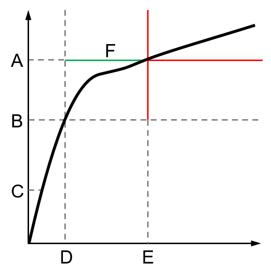
A | Minimum torque limit | D | Angle measurement start |
B | Final angle monitoring torque | E | Angle limit |
C | Cycle start | F | Angle range for OK results |
Define the values of the following parameters to get an OK result:
Final angle monitoring torque
Minimum torque limit
Angle limit
Results:
If the Minimum torque limit value is reached within the Angle limit value (measured from Final angle monitoring torque), the result is OK.
If the Minimum torque limit value is not reached within the Angle limit value (measured from Final angle monitoring torque), the result is not OK.
During the test operation, LEDs, buzzer and vibration are activated as follows:
LED:
White LED: activated when the Cycle start is reached.
Buzzer:
The beep starts when the torque goes over the Cycle start value; the signal increases when the minimum torque is reached / the tightening process has been completed.
Vibration:
Starts when the residual torque is detected.
At the end of the test operation, LEDs, buzzer and vibration are activated as follows:
LEDs:
Green LEDs: Minimum torque detected within the Target angle value (measured from Final angle monitoring torque).
Red LEDs: measured torque is lower or higher than Minimum torque and / or angle value is higher than Target angle (measured from Final angle monitoring torque).
Buzzer
Two beeps indicate the end of the operation; if the final result is in the red area, the signal in continuous.
To stop the buzzer, start a new tightening operation or press a button on the tool controller.
Vibration:
Stays active until the torque applied is released.
Minimum after breakaway
This strategy verifies the minimum torque within a user-defined angular range, constrained between Residual Angle Threshold 1 and Residual Angle Threshold 2. The minimum torque must be between the user-defined torque limits, and both Residual Angle Thresholds must be reached for detection.
Parameter | Description |
|---|---|
Inspection Name | Name of the inspection. |
Torque correction coefficient | When extensions are used, the wrench measurement must be compensated to show a more accurate torque value. To calculate the correction coefficient, please refer to How to calculate the Torque Correction Coefficient. When extensions are not used, Torque correction coefficient = 1. |
Angle correction coefficient | When extensions cause additional wrench bending, the wrench angle measurement must be compensated to show a more accurate angle value. When extensions are not used, Angle correction coefficient = 0. |
Cycle start | Torque value from which the test operation starts. |
Minimum torque limit | Minimum torque value that must be reached within the Target angle value in order to get an OK result. |
Maximum torque limit | Upper torque limit value. |
Change screw | If the torque applied reaches this limit, the message Change screw is shown on the wrench display. The Change screw must be equal or higher than the Maximum limit torque. |
Target torque | Torque target value. |
Torque tolerance | Torque tolerance that defines the maximum torque and the minimum torque according to the Target torque previously specified. Value is expressed in percentage (%). |
Final angle monitoring torque | Torque value from which the angle measurement starts (usually set to 50% of the Target torque). |
Control mode | Method to define the torque limits from the following options:
|
Residual angle threshold 1 | Maximum angle value (measured from the Final angle monitoring torque) for the residual torque when the residual torque is lower than the breakaway point. |
Residual angle threshold 2 | Maximum angle value (measured from the Final angle monitoring torque) for the residual torque when the residual torque is lower than the breakaway point. The Residual angle threshold 2 must be higher than the Residual angle threshold 1 . |
Number of sample | Number of tests to run inside the inspection. |

T0 | Final angle monitoring torque | T1 | Minimum torque |
a1 | Residual Angle Threshold 1 | a2 | Residual Angle Threshold 2 |
B | Breakaway |
Results:
If the Minimum torque is between the torque range and both thresholds are reached, the result is OK.
If the torque trace is monotonic or if the second angle threshold is not reached, the result is not OK.
Intersection
This strategy verifies that the result is the intersection point of two lines, which are drawn from the points where the trace intersects with four user-defined angle thresholds.
Parameter | Description |
|---|---|
Inspection Name | Name of the inspection. |
Torque correction coefficient | When extensions are used, the wrench measurement must be compensated to show a more accurate torque value. To calculate the correction coefficient, please refer toHow to calculate the Torque Correction Coefficient. When extensions are not used, Torque correction coefficient = 1. |
Angle correction coefficient | When extensions cause additional wrench bending, the wrench angle measurement must be compensated to show a more accurate angle value. When extensions are not used, Angle correction coefficient = 0. |
Number of sample | Number of tests to run inside the inspection. |
Cycle start | Torque value from which the test operation starts. |
Minimum torque limit | Minimum torque value that must be reached within the Target angle value in order to get an OK result. |
Maximum torque limit | Upper torque limit value. |
Change screw | If the torque applied reaches this limit, the message Change screw is shown on the wrench display. The Change screw must be equal or higher than the Maximum limit torque. |
Target torque | Torque target value. |
Torque tolerance | Tolerance that defines the maximum torque and the minimum torque according to the Target torque previously specified. Value is expressed in percentage (%). |
Final angle monitoring torque | Torque value from which the angle measurement starts (usually set to 50% of the Target torque). |
Control mode | Method to define the torque limits from the following options:
|
Residual angle threshold 1 | Maximum angle value (measured from the Final angle monitoring torque) for the residual torque when the residual torque is lower than the breakaway point. |
Residual angle threshold 2 | Maximum angle value (measured from the Final angle monitoring torque) for the residual torque when the residual torque is lower than the breakaway point. The Residual angle threshold 2 must be higher than the Residual angle threshold 1 . |
Residual angle threshold 3 | Maximum angle value (measured from the Final angle monitoring torque) for the residual torque when the residual torque is lower than the breakaway point. The Residual angle threshold 3 must be higher than the Residual angle threshold 2. |
Residual angle threshold 4 | Maximum angle value (measured from the Final angle monitoring torque) for the residual torque when the residual torque is lower than the breakaway point. The Residual angle threshold 4 must be higher than the Residual angle threshold 3 . |
Ratchet time | Starts when the torque goes below the Cycle start without reaching the 3rd percentage value. This allows the operator to release the torque for a while and recharge during the tightening operation. |
|
|


T0 | Final angle monitoring torque | T1 | Minimum torque |
a1 | Residual Angle Threshold 1 | a2 | Residual Angle Threshold 2 |
a3 | Residual Angle Threshold 3 | B | Breakaway |
Results:
If the value is between the user-defined torque range, the result is OK.
If the last angle threshold is not reached, the result is not OK.
Pitch Change
This strategy verifies the first point along the trace where the slope change not more than the specified slope change parameter. The trace is analyzed between the range from Residual Angle Threshold 2 to Residual Angle Threshold 1.
Parameter | Description |
|---|---|
Inspection Name | Name of the inspection. |
Torque correction coefficient | When extensions are used, the wrench measurement must be compensated to show a more accurate torque value. To calculate the correction coefficient, please refer toHow to calculate the Torque Correction Coefficient. When extensions are not used, Torque correction coefficient = 1. |
Angle correction coefficient | When extensions cause additional wrench bending, the wrench angle measurement must be compensated to show a more accurate angle value. When extensions are not used, Angle correction coefficient = 0. |
Number of sample | Number of tests to run inside the inspection. |
Cycle start | Torque value from which the test operation starts. |
Minimum torque limit | Minimum torque value that must be reached within the Target angle value in order to get an OK result. |
Maximum torque limit | Upper torque limit value. |
Change screw | If the torque applied reaches this limit, the message Change screw is shown on the wrench display. The Change screw must be equal or higher than the Maximum limit torque. |
Target torque | Torque target value. |
Torque tolerance | Tolerance that defines the maximum torque and the minimum torque according to the Target torque previously specified. Value is expressed in percentage (%). |
Final angle monitoring torque | Torque value from which the angle measurement starts (usually set to 50% of the Target torque). |
Control mode | Method to define the torque limits from the following options:
|
Residual angle threshold 1 | Maximum angle value (measured from the Final angle monitoring torque) for the residual torque when the residual torque is lower than the breakaway point. |
Residual angle threshold 2 | Maximum angle value (measured from the Final angle monitoring torque) for the residual torque when the residual torque is lower than the breakaway point. The Residual angle threshold 2 must be higher than the Residual angle threshold 1 . |
Slope change | Detect residual torque by tracking changes in angle during final tightening. It works whether the breakaway point and residual point are at the same place or not. |
Ratchet time | Starts when the torque goes below the Cycle start without reaching the 3rd percentage value. This allows the operator to release the torque for a while and recharge during the tightening operation. |


T0 | Final angle monitoring torque | T1 | Minimum torque |
a1 | Residual Angle Threshold 1 | a2 | Residual Angle Threshold 2 |
Results:
The result is the first point where the slope changes more than the allowed limit within the specified angle range.
Traceability Tags
Traceability tags are additional attributes that can be linked to routes in QA Supervisor. If a route is configured with traceability tags, during the test the operator must provide the tags to QA Inspector when requested to. According to how the route's traceability tags have been configured in QA Supervisor, there are different methods and moments in which the tags have to be provided.
Traceability tags can be requested at different Levels within the operation:
Level | Description |
|---|---|
Route | Traceability tag requested either before or after the first measurement of the first inspection in the route, depending on the configured Collection Point. |
Inspection | Traceability tag requested either before or after the first measurement in the inspection, depending on the configured Collection Point. |
Part (piece) | Traceability tag requested either before or after the first measurement of each part/piece in the route, depending on the configured Collection Point. This Level is available only for Forced by Piece Routes. |
Sample | Traceability tag requested either before or after each measurement (sample) in the inspection, depending on the configured Collection Point. |
Traceability tags can be requested in different Collection Points of the specified operation level:
Collection point | Description |
|---|---|
Before | Traceability tag requested before starting a measurement according to the selected Level. |
After | Traceability tag requested after finishing a measurement according to the selected Level. |
Traceability tags can be provided to the system from different Sources:
Source | Description |
|---|---|
Keyboard | The operator has to manually type a text string using the device keyboard when prompted. |
Barcode | The operator has to scan a barcode when prompted. |
Picklist | The operator has to select an item from a Picklist configured for the route when prompted. |
If the traceability tag is configured as optional in QA supervisor, it is possible to skip the requests without providing the tag.
If the Traceability tag on resume option is enabled in QA supervisor, the traceability tag is requested when an incomplete test is resumed.
Below are some examples of tests with different traceability tag configurations:
Example 1
The traceability tag is configured with the following parameters:
Level: Route.
Source: Barcode.
Collection point: Before.
Operations:
Configure a route with more than one inspection.
Start the route.
Select the inspection.
Barcode scan is requested.
Scan the barcode.
Complete the route.
If the route is repeated without leaving the Route page, the barcode scan is not requested a second time.
The barcode scan is required only at the beginning of the first inspection of the route.
Example 2
The traceability tag is configured with the following parameters:
Level: Inspection.
Source: Picklist.
Collection point: After.
Operations:
Configure a route with two inspections.
Start the route.
Select the inspection.
Run the test.
After the first result of the inspection, a picklist is displayed on the measuring device's interface: select a tag from the list.
Complete the inspection.
Select another inspection.
Run the test.
After the first result of the inspection, a picklist is displayed on the measuring device's interface: select a tag from the list.
Complete the inspection.
Example 3
The traceability tag is configured with the following parameters:
Level: Part (piece).
Source: Barcode.
Collection point: Before.
Operations:
Start the route.
Select the inspection.
Before collecting the first result, the barcode scan is requested.
Scan the barcode, so that the first part (piece) is linked to the tag.
The barcode scan is not required for the first test points of the other inspections in the route.
Before collecting the second result of the first inspection, the barcode scan is required.
Scan the barcode, so that the second part (piece) is linked to the tag.
The barcode scan is not required for the second test points of the other inspections in the route.
This process is repeated for a number of times equal to the number of parts (piece to test).
Example 4
The traceability tag is configured with the following parameters:
Level: Sample.
Source: Keyboard.
Collection point: After.
Operations:
Start the route.
Select an inspection.
After each result, the input from the keyboard is required.
Correction Coefficients for Extensions
When the joint design or space limitations preclude the use of standard sockets or tools, it may be necessary to use special extension spanners to fit the application. In these cases, the STRwrench measurement can be adequately compensated since the factory calibration is made for the standard arm, and the extension arm increases the torque measured proportionally to its length. The angle measured could also be affected by the extensions, due to its specific torsion when torque is applied.
When a torque multiplier is used on the STRwrench, the torque applied on the joint is greater than the torque produced by the wrench; in this case the torque correction coefficient is used to adjust the wrench torque reading. The angle measurement is also affected, but the wrench cannot compensate the angle measurement.
How to calculate the Torque Correction Coefficient

D | Torque value displayed | T | Torque applied |
L | Standard arm (from the center of the handle to the center of the end fitting tool) | L+E | Total arm |
E | Extension arm |
From the relation between the displayed and applied torque  , the Torque correction coefficient is given by the following formula:
Torque correction coefficient = 
The Torque correction coefficient alters the wrench torque measurement; a wrong value for this coefficient may cause an improper torque reading, and the risk of doing a tightening at a target torque different from the one expected. Ensure you have calculated the proper value when an extension is used.
For end fitting tools used without wrench extensions, the Torque correction coefficient must be left set to 1.
When using an extension, the handling position affects the torque reading. Always position the hand on the center of the STRwrench handle.
If a torque multiplier is used on the STRwrench, the Torque Correction Coefficient must be set equal to the torque multiplying coefficient of the torque multiplier.
The Torque correction coefficient is given by the following formula:
Torque correction coefficient = Torqueoutput / Torqueinput
How to Calculate the Angle Correction
When a wrench extension is used, the Angle Correction allows linear compensation of the extension torsion based on the torque applied. The correction value is expressed in degrees at the smartHEAD Max torque.
Create and configure an inspection with the following values:
Cycle start = smartHEAD Min torque value (usually 5% of smartHEAD Max torque).
Final angle monitoring torque = Cycle start
Target torque = 75% of smartHEAD Max torque
Perform three tightenings at 75% of the smartHEAD Max torque.
For each torque and angle value measured, perform the following calculation:
Angle correction = Angle measured x (smartHEAD Max torque - smartHEAD Min torque) / (Torque measured - smartHEAD Min torque)
Make sure the minimum and maximum angle values calculated do not differ by more than 10% of the maximum value calculated:
Angle correctionmax - Angle correctionmin ≤ Angle correctionmax / 10
If they differ by more than 10%, repeat the procedure from the beginning.
Average the three angle values calculated to obtain the Angle correction.
When a torque multiplier is used on the STRwrench, the Angle correction value must be left to zero; in this case the STRwrench cannot compensate the angle measurement.
Maximum number of application items
Item | Maximum number |
|---|---|
Joints | 10000 |
Routes | 100 |
Inspections per route | 500 |
Inspections per joint | 10 |
Results | 50000 |
Measurements | 50000 |
Traces | 50000 |