Introduction
In this section, you can find the basic information about the product and also the formatting conventions used in the topics.
General Data Protection Regulation (GDPR)
This product offers the possibility to process personal identifiable information such as system user name, role and IP-address. The purpose of this processing capability could be to enhance quality control through traceability and proper access management.
If you decide to process personal data you need to be aware of and comply with relevant personal data protection rules, including, in the EU the GDPR as well as other applicable laws, directives and regulations. Atlas Copco can in no way be held liable for any use made by you of the product.
Software Introduction
ToolsTalk Service 2 is a PC software package that offers an easy and user friendly interface for Atlas Copco devices.
Revision History
Document Revision | Software Version | Change |
|---|---|---|
8 | 1.13 | New:
|
7 | 1.12 | No changes. New version 1.12 due to software release 1.12 |
6 | 1.11 | No changes. New version 1.11 due to software release 1.11 |
5 | 1.9 | New:
Updated:
|
4 | 1.8 | New:
Updated:
|
3 | 1.7 | New:
New service tasks:
Updated:
|
2 | 1.6 | Updated:
|
1 | 1.5 | First edition |
Conventions
To enhance user understanding, certain formatting conventions are used throughout this document. The formatting conventions used are listed below.
Element | Notation | Description | Output |
|---|---|---|---|
General emphasis | In the Program workspace. | To make certain text elements stand out, or to highlight. | Text in Bold |
Graphical User Interface (GUI) items | Select the Function button. | Any reference to items found on screen in the GUI (for example, command buttons, icon names and field names). | Text in Bold |
Graphical User Interface (GUI) Path > | Generally, on the top of the GUI. | Navigation aid which keeps track of the location in the GUI. | For example: Controller > Program > Edit |
User input | Enter a Description for the program. | Any text input by the user. | Text in Bold |
File names | Enter a File Name for the export. | Files either exported from, or imported into the system. | Text in Bold Italic |
Variable and parameter names | Enter a Name for the export. | Variable and parameter names (not values). | Text in Italic |
Variable and parameter values | Enter a VALUE for the export. | Variable and parameter values. | Text in BOLD CAPS |
System output | Client.Domain.Models.ExportImportConfiguration | Any text output by the system. | Text in Monospace |
External links | Links to external sites that have information connected to the document or subject content. These could include:
| Selectable text to external sites | |
Internal documentation links |
If available, these links will be presented below the text. | Selectable text to internal content |
System Overview
The User Interface
The menus and settings available in ToolsTalk Service 2 will vary depending on what tool is connected to the software. Different tabs, views, settings and tasks will be available dependent on the tool. If an option is not visible, that option is not available for that specific tool.
Some settings might be grayed out. These settings are available for the connected tool, but are not currently active.
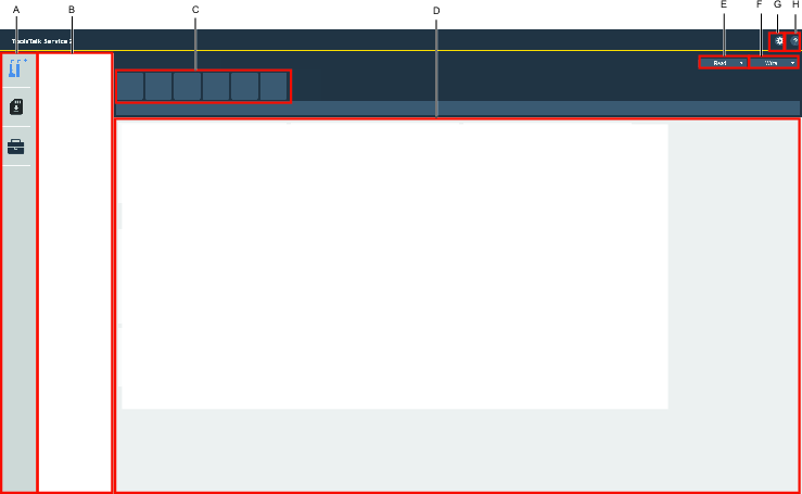
A | Left-side menu bar |
B | Device list |
C | Feature tabs |
D | Information display |
E | READ drop-down box |
F | WRITE drop-down box |
G | Application settings |
H | Application information |
Software Icons
Features in ToolsTalk Service 2 user interface:
Icon | Description |
|---|---|
| Devices tab |
| Copy Firmware tab |
| License Manager tab |
| READ button |
| WRITE button |
| WRITE Parameter button |
| Application Information icon |
| Pending changes |
| Drill speed Ccalculator |

Feature Tabs
The information displayed will vary depending on the type of device that is connected.
Example of Features:
Icon | Tab dscription |
|---|---|
| Device Information |
| Wireless Settings |
| Service Tasks |
| General Settings |
| Drill Programs |

The Device List
The Device Adapter Information will always display when it is connected to the computer. The Device Information will be displayed for those devices that have been connected or discovered using the device adapter.
If there is a problem with the connection, the error information for the device will be visible in the software, for example [SERIAL NUMBER UNKNOWN].
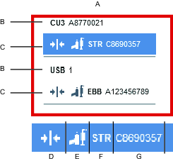
A | Device List |
B | Device Adapter Information |
C | Device Information |
D | Connection Verification |
E | Device Type Icon |
F | Device Type Family |
G | Device Type Serial Number |
The Device List
The Device Adapter Information will always display when it is connected to the computer. The Device Information will be displayed for those devices that have been connected or discovered using the device adapter.
If there is a problem with the connection, the error information for the device will be visible in the software, for example [SERIAL NUMBER UNKNOWN].
A | Device List |
B | Device Adapter Information |
C | Device Information |
D | Connection Verification |
E | Device Type Icon |
F | Device Type Family |
G | Device Type Serial Number |
The Information Icon
The information icon  can be used to read further information available. Hover over the icon, to expand and view the information.
Application Information
The ToolsTalk Service 2 software version and edition can be found in the Application Information
 button.
Pending Changes
Changes made will be marked with icon  .
.
Implement Changes
Select WRITE to implement the changes to the device.
Restore Changes
Select READ to discard the changes made and restore the previous status of the device.
The device need to be connected to ToolsTalk Service 2 for the changes to be transferred to the tool. It not, the changes will be lost.
Installation and Upgrade
In this section, you can find information to help with the initial installation of the product, or upgrading from one version to another.
Installation Restrictions
Computer Requirements
To run the ToolsTalk Service 2 software the following minimum computer requirements need to be met:
Area | Category | Minimum requirements | Comments |
|---|---|---|---|
Computer client requirements | Operating system | Windows 10 or 7 (SP1) 64-bit version | |
Processor | 1 gigahertz (GHz) or higher 64-bit Intel or AMD processor | ||
RAM | 2 gigabytes (GB) or more | ||
Display resolution | 1024x768 pixels or higher | ||
Disk space | 2 gigabytes (GB) or more | The ToolsTalk Service 2 application and database require at least 2 gigabytes (GB) of free disk space, in addition to the operating system disk space requirements. | |
Network card | A configured network card |
A docking station is required in order to connect to SB or STB tools (Atlas Copco Industrial Technique AB product number 8433 3900 50).
A Communication Unit 3 (CU3) is required in order to connect to cable tools (Atlas Copco Industrial Technique AB product number 8092 1168 15).
Older versions of the CU3 are not compatible with the ToolsTalk Service 2 software.
If USB hubs are used to connect CU3s and Docking Stations (DS) to a PC running the ToolsTalk Service 2 software, it is recommended not to mix CU3s and DS on the same hub.
If USB hubs are used to connect CU3s and DS to a computer running the ToolsTalk Service 2 software, it is recommended not to connect several USB hubs in cascade.
It is recommended to only use certified USB cables and hubs when connecting external USB equipment. For example, DS, CU3s and SRB/TBP tools connected to the computer running ToolsTalk Service 2 (certified USB products are registered at USB.org).
Before Installing
Before starting the installation, make sure the following are available:
Before starting the installation, make sure the following are available:
Administrator rights to the computer which the application is to be installed on.
Computers and programs according to the listed requirements.
Software
Installing the Software
The ToolsTalk Service 2 installer always installs the following components on the computer:
ToolsTalk Service 2 database, containing device interfaces for available accessories, cables and tools.
Download and install Microsoft .NET Framework 4.8 on the computer, to be able to use ToolsTalk Service 2. https://dotnet.microsoft.com/download/dotnet-framework/net48
Download and install Runtime and not Developer Pack.
The ToolsTalk Service 2 installer will automatically install Microsoft Visual C++ 2017 Redistributable Package to the computer, if it is not already installed.
Select to install the (.exe) software file.
If an installation control appears, select OK to enable the installation to make changes on the hard drive.
In the ToolsTalk Service 2 InstallShield Wizard window, select Next.
Read the License Agreement.
Select the I accept the terms in the License Agreement check box, and then select Next.
In the Destination Folder, either select Next to proceed with the installation, or select Change to open a different destination folder before proceeding.
The software is now ready to install, either select Install to proceed, or select Cancel to exit the installation.
When the installation process is done, select Finish.
Uninstalling the Software
ToolsTalk Service 2 software can be uninstalled in two ways.
Uninstalling the Software Using the Computer
On the Windows Control Panel select Programs , and go to Programs and Features, select and uninstall the desired software.
Uninstalling the Software Using the InstallShield Wizard
Locate the executable file that was used to install the software.
Select the executable file.
On the start screen of the InstallShield Wizard, select Next.
Select the Remove option button, and select Next.
Select Remove, to remove the software.
Select Finish to complete the wizard.
It may be necessary to restart the computer for the changes to take effect.
Upgrading the Software
Follow the same steps as for Installing the Software.
Downgrading the Software
In some cases it is useful to downgrade ToolsTalk Service 2 to a previous version.
Uninstall the current version of ToolsTalk Service 2.
Install the older version of ToolsTalk Service 2.
Hardware
Compatibility
Tool Compatibility
ToolsTalk Service 2 is compatible with the following tool families:
ST, SL
SB, STB
SR, STR
PST, QST
SRB, SRB-HA, TBP, TBP-S
DL, ES
EBB, EBP
ICB, ITB, IPB
Working with Device Adapters
Connecting devices such as tools requires a Device Adapter.
Docking Station (DS) - Device interface by the tool battery connection.
Communication Unit 3 (CU3) - Device interface by tool cable.
Built in Device Adapter (USB) - Device interface by USB cable.
Multiple Device Adapters may be connected to the computer at the same time, but only one device may be connected in the application at a time per Device Adapter.
Installing a Device Adapter
IMPORTANT! ToolsTalk Service 2 software must be installed before any Docking Station (DS), Communication Unit 3 (CU3), and/or Built in Device Adapters (USB), with Device Adapter are connected to the computer.
Install the ToolsTalk Service 2 software.
Connect a Docking Station (DS), Communication Unit 3 (CU3), and/or Built in Device Adapters (USB), to the computer.
Wait until Windows has installed the Device Adapter.
Start the ToolsTalk Service 2 software.
Connecting a Device to a Communication Unit 3 (CU3)
The CU3 is a Device Adapter that supports connectivity with devices such as tools, tool cables or tool accessories.
Do not try to connect a device using Communication Unit 1 (CU1) or Communication Unit (CU2), as they are not compatible.
When using a device together with an extension cable, only one extension cable and device can be connected to the CU3 at any one time.
Start ToolsTalk Service 2 on the computer.
Connect the Device Cable to the Communication Unit CU3.
Connect the Communication Unit CU3 to the power supply.
Connect the Communication Unit CU3 to the computer using the USB cable.

If new firmware is available for a connected Communication Unit CU3, a notification is displayed. Make sure to always use the latest firmware for the Communication Unit CU3.
Connecting a Device to a Docking Station (DS)
The Docking Station (DS) supports connectivity for STB and SB tools.
Start ToolsTalk Service 2 on the computer.
Remove the battery from the device.
Connect the tool to the Docking Station (DS).
Connect the Docking Station (DS) to a power supply.
Connect the Docking Station (DS) to the computer using the USB cable.
Connecting a Device with a Built In Device Adapter (USB)
Devices with a Built In Device Adapter must be powered by a battery.
Start ToolsTalk Service 2 on the computer.
Connect the device to the computer using the USB cable.
Configuration
In this section, you can find detailed information about how to create, modify, and verify product settings.
Working with the License Manager
The software requires a license before it is possible to use. The license activation code is obtained from the license issuer.
The activation code for the software is then used to activate the software in the License manager  .
.
The software license is bound to a specific computer, based on machine profiling information when the license is redeemed. Changing the machine configuration or setup after the license has been activated might render the license invalid. If this happens please contact the license issuer for assistance.
License Status
When starting ToolsTalk Service 2, the software will check and validate the stored license.
The License Status is GREEN when the application has been activated with a valid license.
The License Status is RED when there is no valid license.
The license validation is displayed in the Expiration Date field.
Activating a License Online
In order to use ToolsTalk Service 2, the license has to be activated using an Activation Code or License Token.
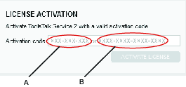
A | License Token | B | Activation Code |
Code Types:
License Token, XXX-XXX-XXX - Physically delivered license.
Activation Code, XXXX-XXXX-XXXX-XXXX - Electronically delivered license.
Using an Activation Code
Contact your license issuer to obtain a valid activation code.
Enter the activation code into the Activation code box.
Select ACTIVATE LICENSE.
Using a License Token
Locate the License Token which is delivered together with a product, for example upgrade kits.
Enter the License Token into the Activation code box.
Select ACTIVATE LICENSE.
Activating a License Offline
If the computer does not have internet access and the License Status is not valid, the license has to be activated offline.
Contact the license issuer to initiate the offline activation.
When the Activation code has been received from the license issuer, follow the procedure.
On the License Manager tab, in the LICENSE INFORMATION menu, tick the Use offline files check box.
Enter the received activation code into the Activation code box, and then select SAVE FILE.
You will receive a Capability Request file.
Save the Capability Request file to a removable disc.
Move the removable disc with the Capability Request file to a computer with internet access.
Send the Capability Request file to the license issuer.
A Capability Response file (.bin) will be sent in return, from the license issuer.
Save the Capability Response file to the removable disc.
Move the removable disc with the Capability Response file to the computer with ToolsTalk Service 2 installed.
Select OPEN FILE to open the Capability Response file and activate the license.
Synchronizing a License Online
This feature is used, for example, when moving a license to another computer.
On License Manager, in the LICENSE SYNCHRONIZATION, select SYNCHRONIZE LICENSE.
When the synchronization is ready, select OK.
Synchronizing a License Offline
This task always involves the license issuer.
It is possible to synchronize the license offline by manually transferring a capability (.bin) file.
Contact the license issuer to initiate the synchronizing.
On the License Manager tab, in the LICENSE INFORMATION menu, tick the Use offline files check box.
Select SAVE FILE and save the capability request file on the computer.
Send the capability request file to the license issuer.
The license issuer will return a capability response file.
Select OPEN FILE to open the capability response (.bin) file.
Select SAVE FILE and send it to the license issuer.
Moving a License to a New Computer
This task always involves the license issuer.
Contact the license issuer to initiate the move.
After receiving the confirmation to proceed, synchronize the license on the old computer.
Activate the license on the new computer.
Operation
In this section, you can find step-by-step information about how to operate the product.
- Before Starting the Software
- Connecting to a Device
- Disconnecting From a Device
- Copying Firmware to a Tool
- Working with the Read Button
- Working with the Write Function
- Synchronizing the Device Data
- Creating a Problem Report
- Device Information
- Working with the General Settings Tab
- Working with the Drill Programs Tab
- Working with the Wireless Settings Tab
- Working with the Service Tasks Tab
Before Starting the Software
IMPORTANT! ToolsTalk Service 2 software must be installed before any Docking Station (DS), Communication Unit 3 (CU3), and/or Built in Device Adapters (USB), with Device Adapter are connected to the computer.
Install ToolsTalk Service 2 software.
Connect the Docking Station (DS), Communication Unit 3 (CU3), and/or Built in Device Adapters (USB).
Start the ToolsTalk Service 2 software.
Connecting to a Device
Connect to an Adapter Device
This type of connection works for Device Adapters, such as tools.
In ToolsTalk Service 2, select the Device Adapter on the Device list,
Select Connect on the screen. Alternatively, right-click on the Device Adapter in the Device list and then select Connect
Discover a Device
This type of connection works for devices, such as accessories on a tool, tool cables, and extension cables that are not attached to a tool. The feature will discover all the devices available for a specific Device Adapter tool. Depending on which type of cable it is, there are limits.
It is only possible to connected to one device per Device Adapter, at a time.
In ToolsTalk Service 2, right-click on the Device Adapter.
In the Device list select Discover. It will display any devices available.
Select the device in the Device list and then select Connect on the screen.
When a device is connected, the parameters will need to be read to be able to make adjustments in the application.
If there is a problem connecting to a device, or there is a mismatch between the number of discovered accessories in the device list and the number of accessories identified by visual inspection, then this may be an indication that there is a problem with one or more of the attached accessories, see Troubleshooting.
Device Connection
To connect to a tool, the tool must be attached to a tool cable. A tool can never be connected to an extension cable.
To connect to a tool cable, no extension cable or tool can be attached to the tool cable.
To connect to an extension cable, no tool or tool cable can be attached to the extension cable.
Disconnecting From a Device
Disconnecting communication from the device using ToolsTalk Service 2.
Right-click on the Device Adapter in the device list and then select Disconnect.
Copying Firmware to a Tool
This function only supports tools using SD memory cards.
Disconnect the tool from ToolsTalk Service 2 (select disconnect in UI and remove USB cable).
Remove the battery from the tool.
Remove the SD memory card from the tool, and then insert it into the computer.
Select download
 , then the COPY FIRMWARE screen will be displayed.
On the COPY FIRMWARE screen, choose whether to copy the firmware from the database or browse for a local file.
Select COPY.
When the copying is completed, remove the SD memory card from the computer.
Insert the SD memory card back into the tool.
Connect the USB cable to the tool.
Reinstall the battery and select Connect in ToolsTalk Service 2.
The tool starts an autonomous action in order to install the firmware.
The tool may request the user to run the Factory Reset service task or Default Reset service task (depending on the firmware used).
Working with the Read Button
The READ drop-down box  , can be used to read all parameters from a device or from a file. When a device is connected, the parameters will need to be read to be able to make adjustments in the application. Alternatively, a previously exported parameter file can be read into the application.
Reading Data from a Device
This function enables the user to read data from a device, such as parameters including Wireless Settings.
In the ToolsTalk Service 2 toolbar, select the READ button to read data from the device.
Working with the Write Function
The WRITE drop-down box  , can be used to write all parameter changes to a device, or for exporting data to a file.
The WRITE button  , can be found in the firmware tab. It enables the user to write that specific parameter or firmware to a device.
Changes made will be marked with icon .
Select WRITE to implement the changes to the device.
Select READ to discard the changes made and restore the previous status of the device.
Writing Data to a Device
In the ToolsTalk Service 2 main toolbar, select the WRITE drop-down box and select To Device, to write the data to the device.
The device properties will vary depending on the type of device that is connected.
Writing Data to a File
Parameter information including Wireless Settings, can be exported as a .TTX file and saved on a computer or on a selected media.
In the ToolsTalk Service 2 main toolbar, select the WRITE drop-down box.
Select To File.
On the computer or on the selected media, select the folder and then select Save, to store the data.
Select OK.
Synchronizing the Device Data
ToolsTalk Service 2 comes with a local database as standard. This feature can be used to download new device data that will be stored in a separate database.
Select the Application Settings button
 .
.Select Synchronize device data to download the local device data.
Select Continue to start the download.
Select OK after successful data download.
Select database type Local - Synchronized from the drop-down list.
Select Save settings to verify the settings.
Creating a Problem Report
If a problem occurs with ToolsTalk Service 2, create a Problem Report as soon as possible. This can then be attached to a help ticket or email and then reported through the appropriate channel.
Select the Application Information icon
in the main menu bar.Select PROBLEM REPORT, and then select SAVE FILE.
Browse to the desired save destination and select SAVE.
Device Information
Device Information is displayed in the Information Tab  . The tab contains identity information about the connected device and the software within the device. Example of the identity information of the device are Product name, Product number, Serial number, Variant, Software version. The information is divided into properties.
The device properties will vary depending on the type of device that is connected.
Working with the General Settings Tab
The device properties will vary depending on the type of device that is connected.
On the General Settings tab  , you can configure the device properties. When starting ToolsTalk Service 2, the general settings properties have not yet been read from the device, this is done using the READ function.
Enter the desired property value or text in the entry field.
The greyed out property fields cannot be edited or changed.
Setting the Tool Startup Text
The text that is shown on the tool display during the tool startup, can be changed.
In the General Settings tab, on the HMI properties, select the Display to On on the drop-down list.
On Custom text, enter the desired text.
Configuring the Power Saving
On the General Settings tab , go to the POWER SAVING properties. In the Tool inactivity timeout settings, enable power saving for the tool.
The possible selections are:
Off
10 min
20 min
30 min
Configuring the Front LED
The Front LED on the device can be configured using ToolsTalk Service 2.
On the General Settings tab, go to the FRONT LED properties. In the Front LED setting, select Enable/Disable from the drop-down list.
In the Intensity text box, enter the level of intensity in %.
In the Power off delay text box, enter the delay time in ms.
In the Show in tool menu drop-down list box, select On/Off.
Total Tool Usage
On the General Settings tab , go to the TOTAL TOOL USAGE properties. This area contains information about the tool usage.
Example of tool usage:
Hole count
Drill time
Drill energy
Trigger press count
Power cycle count
Working with the Drill Programs Tab
The device properties will vary depending on the type of device that is connected.
On the Drill Programs tab  , a list containing the different drill programs is displayed.
The functions on the Drill Programs tab are:
Configuring drill programs.
Reordering the drill program list.
ADD drill programs.
Manage drill programs:
Delete drill programs.
Activate drill programs.
Deactivate drill programs.
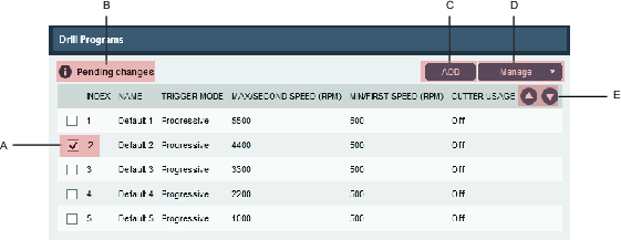
A | Program index number and program selection check box. | D | Manage button. |
B | Pending changes, changes made waiting to be written to the tool. | E | Arrow buttons to reorder programs. |
C | ADD button. |
Reordering the Drill Program List
On the Drill Programs tab , the drill program list can be reordered by moving the program up or down, with help of the Arrow buttons.
Select the check box for the drill program that you want to move.
Select the Arrow buttons in the column header to move the drill program up or down in the list.
The Index number for the program is now changed to match the new position.
Managing Drill Programs
Via the Managing drill programs feature, it is possible to select and manage a program:
Activate
Deactivate
Delete
Activating Drill Programs
On the Drill Programs tab
, in the program list, select the check box for the drill program that you want to activateSelect the Manage drop-down box, and then select Activate from the list.
The program will get a new index number when activated.
Deactivating Drill Programs
On the Drill Programs tab
, in the program list, select the check box for the drill program that you want to deactivate.Select the Manage drop-down box, and then select Deactivate from the list.
The deactivation of a program results in a change of order in the program list, the deactivated program is placed last and the information is inactive without an index number.
Deleting Drill Programs
On the Drill Programs tab
, in the program list, select the check box for the drill program that you want to delete.Select the Manage drop-down box, and then select Delete from the list.
Adding Drill Programs
Select ADD to add a new program, then enter the setup parameters for the new program.
Configuring Drill Programs
Select the chosen program in the program list, and enter the drill program configuration.
Configuring the Trigger Mode
On the Drill Programs tab
, double-click one of the programs, when the program edits opens go to the GENERAL properties. In the Trigger mode settings, select the speed for the selected drill program.
Index: The program index number.
Name: Name the program.
Trigger mode:
Progressive:
Min speed. Configurable between 500-Max speed.
Max speed. Configurable between (the lowest of 1000 RPM and Min speed) to 5500.
Two speed:
First speed. Configurable between 1000-5500.
Second speed. Configurable between 1000-5500.
Configuring the Cutter Usage
On the Drill Programs tab , double-click one of the programs. In the CUTTER USAGE properties, the settings are made for utilizing the drilling time more efficiently.
Go to the CUTTER USAGE properties. Set the Cutter usage selection to On, to enable cutter usage.
Cutter usage:
On: Enable cutter usage.
Off: Disable cutter usage.
Program usage since reset:
Drill time: Drill time information since last reset
Drill energy: Drill energy information since last reset
Hole count: Amount of drilled holes since last reset
Program alarm:
Alarm type:
Warning. Enables a warning when the limits are fulfilled.
Lock drill program. Enables locking of tool when the limits are fulfilled.
Limit type:
Drill time. Counts drill time for limit.
Drill energy. Counts drill energy for limit.
Hole count. Counts hole for limit.
Drill limits:
Drill time limit, in mmm:ss.
Drill energy limit, in Joule.
Hole count limit, in number of holes.
For information about how to reset Cutter usage, see the Product Instruction.
Configuring the Modular Head
On the Drill Program tab
, go to the MODULAR HEAD properties. In the Extra gear ratio setting, enter the given Speed Ratio value for the tool, found in the product information.
The speed ratio compensation is a given value and can be found in the product information for the modular drill head.
Setting the Drill Energy Limit
Drill Energy is a method to estimate the cutter usage, based on the energy measured through the cutter, taking into account the drilled time and power used in the tool.
To find the Drill Energy value, drill holes until the cutter is dull, note the Drilled Energy, and then enter that value in the Energy limit parameter.
Setting the Drill Time Limit
Drill Time is a method to estimate the cutter usage based on the time the cutter has been in use.
To find the Drill Time value, drill holes until the cutter is dull, note the Drilled Time, and then enter that value in the Time limit parameter.
Setting the Hole Count Limit
Hole Count is a method to estimate the cutter usage based on the number of holes the cutter has been used for.
To find the Hole Count value, drill holes until the cutter is dull, note the Hole Count, and then enter that value in the Hole Limit parameter.
Calculating Drill Speed
In the Drill program settings, the Drill speed calculator,  , can be used as help when setting the Drill speed parameters, First speed, Second speed, and Max speed. The Min speed parameter cannot be calculated.
When Trigger mode is set to Progressive, Min speed and Max speed are available. When Trigger mode is set to Two speed, First speed and Second speed are available.
Do not mix metric and imperial values when using the calculator.
Select the Drill speed calculator button,
. A new window will open.Enter the following values:
Drill Diameter
Cutting Speed
The resulting Drill Speed is calculated and validated according to applicable tool limits. If the value is not valid a warning will appear. When a valid value is calculated the CONTINUE button is displayed.
Select CONTINUE to close the Calculate window. The calculated value has populated the Drill Speed value box.
Working with the Wireless Settings Tab
The device properties will vary depending on the type of device that is connected.
On the Wireless Settings tab  , the configuration for Wi-Fi, Bluetooth and WLAN are set.
Configuring the Bluetooth Sender Power
Bluetooth functionality is dependent on the device type.
On the Wireless Settings tab
, go to BLUETOOTH properties.Select Sender power and the desired sender power required.
Configuring the Wi-Fi Zone Tethering
On the Wireless Settings tab , go to the WI-FI ZONE TETHERING properties. To configure the Wi-Fi zone tethering, the Wi-Fi zone tethering needs to be set to On, this will open up the WI-FI ZONE TETHERING properties for further configuration.
Status
Hover the mouse over the green, yellow, or red indicator, to see the status descriptions.
Green - Wi-Fi zone tethering is turned on, the wireless settings are password protected, and the Wi-Fi state is enabled.
Yellow - Wi-Fi zone tethering is turned on but Wi-Fi state is disabled. This status has higher priority than the yellow status below.
Yellow - Wi-Fi zone tethering is turned on but the wireless settings are not password protected. This status has lower priority than the yellow status above.
Red - Wi-Fi zone tethering is turned off.
Power on Limit
The number of hours the tool may be powered on before it is locked, when the tool is not connected to the Wi-Fi zone.
Power Cycles Limit
The number of times the tool may be powered on before it is locked, when the tool is not connected to the Wi-Fi zone.
Password
The Wireless settings tab is password protected when Wi-Fi zone tethering is enabled and a password is turned on. The Wireless settings tab will be locked the next time the tool is connected.
Modifying the Password
On the Wireless Settings tab, in the WI-FI ZONE TETHERING properties. Set the Wi-Fi zone tethering selection to On to enable the WI-FI ZONE TETHERING properties.
In the WI-FI ZONE TETHERING properties, select MODIFY PASSWORD.
Passwords are case sensitive.
Action:
Change - Enter your own password and confirm it (high safety)
Clear - Do not use password (no safety)
Use default - Use the default password (low safety).
The default password is password
Configuring the WLAN
On the Wireless Settings tab , go to the WLAN properties. To configure the WLAN, the Wi-Fi state selection has to be set to Enabled, this will open the WLAN properties for further configuration.
Properties | Setting |
|---|---|
Wi-Fi state |
|
SSID | Wi-Fi Network name to connect to |
Tool name | Enter a Tool name that will be visible on the router |
IP configuration |
|
Security mode |
|
Key format |
|
Password | Enter password, length of string 8-63 characters |
Uploading a Certificate
The certificates are used for authentication of the Wi-Fi using security mode PEAP or EAP/TLS.
In the Wireless Settings tab, on CERTIFICATE, select one of the following Operation properties:
Load client certificate
Load client key
Load CA certificate
In File properties, select BROWSE and select the downloaded certificate (.der) from the computer.
Working with the Service Tasks Tab
The device properties will vary depending on the type of device that is connected.
The Service Tasks tab  , enables the user to run different Service Tasks.
Changing the Application Firmware
This is a service task which is used for changing the tool application firmware without losing parameter values.
In the Service Tasks tab, on CHANGE APPLICATION FIRMWARE select START.
On the Select firmware dialog box, select firmware and the desired firmware version in the drop-down list.
Select SELECT.
On the Write firmware package dialog box, select YES to select firmware and for process to begin.
Select OK.
Tuning the Motor
In the Service Tasks tab, on MOTOR TUNE, select START.
Follow the instructions in the Motor tune dialog box.
Select OK, when the tuning is completed.
Tuning the Trigger
In the Service Tasks tab, on TRIGGER TUNE, select START.
Follow the instructions in the Trigger tune dialog box.
Select OK, when the tuning is completed.
Troubleshooting and Service
This section provides assistance in troubleshooting problems, should they arise, and contains information to help you maintain and service the product.
Troubleshooting During Connection
Normal State
The Device is functioning as intended and it is represented by Device Name and Serial Number in the Device List.
[BOOT MODE]
Error | Possible Solution |
|---|---|
The Device is in boot mode and it is represented by the Device Name and the [BOOT MODE] information in the Device List. | Update the Device Firmware and try again. |
[DEVICE UNSUPPORTED]
Error | Possible Solution |
|---|---|
The Device you are trying to connect to is not supported by the current version of ToolsTalk Service 2 software being used. This case is represented by the Device Name and the [DEVICE UNSUPPORTED] information in the Device List. The Device is also disabled in the Device List and it is not possible to interact with it in any way. | Make sure to use the latest version of the ToolsTalk Service 2 software. File an error report if the limitation is not part of the ToolsTalk Service 2 release notes. |
[SERIAL NUMBER UNKNOWN]
Error | Possible Solution |
|---|---|
The ToolsTalk Service 2 is able to communicate with the Device but it is not possible to read the Device Serial Number. This case is represented by the Device Name and the [SERIAL NUMBER UNKNOWN] information in the Device List. | Send the Device for repair. |
[FIRMWARE UNSUPPORTED]
Error | Possible Solution |
|---|---|
The Device Firmware is not supported and it is represented by the Device Name and the [FIRMWARE UNSUPPORTED] information in the Device List. | Update the Device Firmware and try again. |