SP-700-230
Product Information
General Information
Safety Signal Words
The safety signal words Danger, Warning, Caution, and Notice have the following meanings:
DANGER | DANGER indicates a hazardous situation which, if not avoided, will result in death or serious injury. |
WARNING | WARNING indicates a hazardous situation which, if not avoided, could result in death or serious injury. |
CAUTION | CAUTION, used with the safety alert symbol, indicates a hazardous situation which, if not avoided, could result in minor or moderate injury. |
NOTICE | NOTICE is used to address practices not related to personal injury. |
Warranty
Product warranty will expire 12+1 months after dispatch from Atlas Copco's Distribution Center.
Normal wear and tear on parts is not included within the warranty.
Normal wear and tear is that which requires a part change or other adjustment/overhaul during standard tools maintenance typical for that period (expressed in time, operation hours or otherwise).
The product warranty relies on the correct use, maintenance, and repair of the tool and its component parts.
Damage to parts that occurs as a result of inadequate maintenance or performed by parties other than Atlas Copco or their Certified Service Partners during the warranty period is not covered by the warranty.
To avoid damage or destruction of tool parts, service the tool according to the recommended maintenance schedules and follow the correct instructions.
Warranty repairs are only performed in Atlas Copco workshops or by Certified Service Partners.
Atlas Copco offers extended warranty and state of the art preventive maintenance through its ToolCover contracts. For further information contact your local Service representative.
For electrical motors:
Warranty will only apply when the electric motor has not been opened.
Website
Information concerning our Products, Accessories, Spare Parts and Published Matters can be found on the Atlas Copco website.
Please visit: www.atlascopco.com.
ServAid
ServAid is a portal that is continuously updated and contains Technical Information, such as:
Regulatory and Safety Information
Technical Data
Installation, Operation and Service Instructions
Spare Parts Lists
Accessories
Dimensional Drawings
Please visit: https://servaid.atlascopco.com.
For further Technical Information, please contact your local Atlas Copco representative.
Safety Data Sheets MSDS/SDS
The Safety Data Sheets describe the chemical products sold by Atlas Copco.
Please consult the Atlas Copco website for more information www.atlascopco.com/sds.
Country of Origin
For the Country of Origin, please refer to the information on the product label.
Dimensional Drawings
Dimensional Drawings can be found either in the Dimensional Drawings Archive, or on ServAid.
Please visit: http://webbox.atlascopco.com/webbox/dimdrw or https://servaid.atlascopco.com.
Overview
Operating conditions
Reading the present manual is highly recommended to carry out correctly the transport, installation, commissioning, use, regulation, assembly, disassembly and maintenance of the hydraulic unit.
This manual is an integral part of the supplied product; the buyer is responsible for enforcing its careful reading to all the personnel involved with the equipment and those, for any reason, who have to use it or intervene on it.
Unpacking and storage
Upon receiving, make sure to check the contents of the package for obvious damages. Open the package carefully to avoid damaging certain accessories which can be fixed to the inside. Examine the contents and check against the delivery note.
Storage for less than two months must be done preferably in its original packaging and protected from the elements. Storage for a period longer than two months must be done preferably in its original packaging, protected from the elements, with a heat sealed plastic cover and with silica gel sachets inside.
Prior to its storage, any hydraulic oil in the tanks of the hydraulic unit must be emptied.
Description
The SP-700 is a portable and automatic hydraulic unit for tightening bolts by a torque process. It allows reaching pressures up very fast which means a significant time saving in assembly operations. The SP-700 must only be used for the purpose for which it is intended and not for other purposes not listed in this manual.
The main idea behind its development is to reach the greatest grade of simplicity for the user, get a modular design, and great robustness in performance. It reflects the knowledge gained in microelectronics, design of control systems, hydraulics and mechanics through recent years. The SP-700 is the pump that achieves effectiveness in all areas related to product life: low maintenance costs, great increases in productivity, and energy savings, resulting in controlled costs during product life.
The SP-700 can be used in manual mode or in automatic mode. In the manual mode, the user activates the solenoid valve by pressing the green button of the pendant to initiate the movement of the piston. In automatic mode, the control of the pump operates the solenoid valve to initiate the movement of the piston with no intervention of the user. With the new algorithm, the pump detects when the piston have reached full stroke, and activates the retracting movement immediately.
To work in automatic mode, it is necessary to perform a learning cycle that it´s carried out in an autonomous way. By doing these cycles, the pump recognizes the hydraulic behavior of the wrench, no matter the size of the tool or even the manufacturer, memorizing the main parameters to let the algorithm take control of the pump.
The hydraulic pressure group is a compact electro mechanical kit, developed to facilitate the use in different sites and maneuverability, which consist of the following parts:
Submerged electrical motor
Gear pump
Directional solenoid valve
Manifold and secondary solenoid valve
Pressure gauge
Remote control handgrip
Control box
Protective steel frame
Hydraulic oil tank
Pressure regulating manual valve
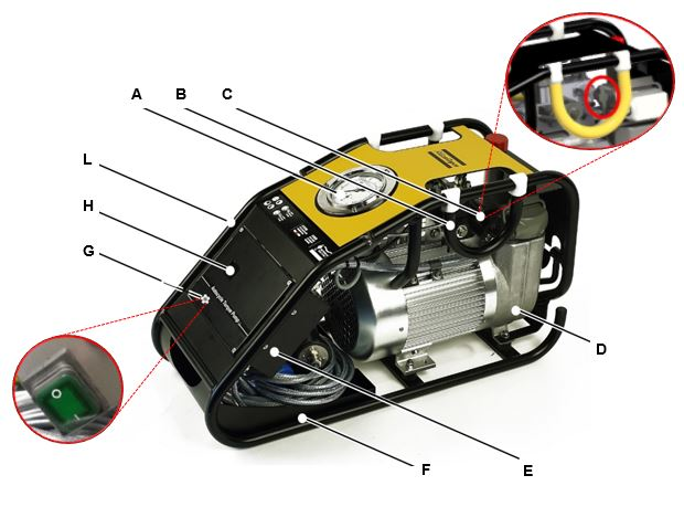
A | Pressure gauge | B | Carrying handle |
C | Regulating pressure valve | D | Oil tank |
E | Control box | F | Cable rack |
G | Main supply switch | H | Display |
L | Hose connectors |
A PLC manages the control of the whole system. It is installed inside of the control box.

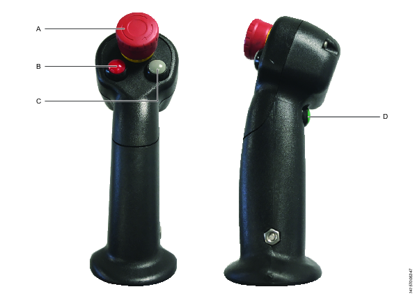
A | Emergency stop switch | B | Stop and pressure release button |
C | Automatic / Manual mode button | D | Start and pressure rise button |
Operating principle
Operating the equipment consists of elevating the pressure through a mix of a gear pump plus a piston pump up to an initial low pressure. They are moved by a one phase electric motor, isolation class B (155˚C) and IP54, valid for continuous or intermittent use. Above this initial pressure, the gear pump flow is redirected into the tank so that only the piston pump continues to raise the pressure until reaching the set value (through a manual valve). This dual pump system allows the motor to reduce the current consumption without affecting the performance.
Product data
| SP-700-230 | SP-700-115 |
|---|---|---|
Current supply | 230 V | 110 V |
Frequency | 50 / 60 Hz | 60 Hz |
Power | 1.8 kW | 1.8 kW |
Rated current | 10.5 A | 20.5 A |
Starting power | 3.3 x IN | 4.5 x IN |
cos φ | 0.94 | 0.95 |
Turning speed | 2800 rpm | 3420 rpm |
Tank capacity | 4.7 l | 4.7 l |
Available volume | 1.7 l | 1.7 l |
Empty weight | 34 kg | 34 kg |
Noise level | 78 db | 78 db |
IP rating | IP54 | IP54 |
Height | 400 mm |
Width | 280 mm |
Length | 680 mm |
Hydraulic oil | see section about hydraulic oil for more information |
Technical Product Data
Technical Product Data can be found on either ServAid, or the Atlas Copco website.
Please visit: https://servaid.atlascopco.com or www.atlascopco.com.
Installation
Installation Instructions
Electrical installation
The power supply circuit board must be in accordance with the current legislation (low tension regulation) and in particular it must have a degree of protection against indirect contacts adequate to the place of installation.
Check the cables for damage, before connecting the equipment. They must be free from erosions or scrapings. All the connections must be carried out with elements standardized for this purpose, marked with their electrical characteristics, which must agree with the characteristics of the power supply and the pressure equipment.
Check that the voltage indicated in the group plate matches the power lead voltage.
If it is necessary to replace the power cable, pay attention to assembly the gland. Before reassembling it, replace the sealing sleeve if possible and properly adjust the pressure dome. Also, if the plug must be replaced, make sure that the connection is perfectly insulated and protected from humidity.
Any intervention in the control panel can lead to the loss of the warranty and the manufacturer’s responsibility, so for this reason it is recommended to send the equipment to the dealer or an authorized maintenance workshop.
Main supply requirements
The SP-700 hydraulic unit has a single phase motor with a power of 1.8 kW. Due to the applications of this machine, usually in the field, with no connection to the main supply, it generally requires the use of autonomous generators.
Because of the peak in power consumption that occurs when starting up of the motor, a minimum power of 16 kVA is required. 20-30 kVA generators, that provide a more stable service, are recommended for these applications.
Bear in mind that the length of cable used to connect the unit is a critical factor in applications of the wind power sector, as it normally exceeds 80 meters from the power supply to the Unit. The voltage drop must be reduced as much as possible, as it can cause malfunction of the hydraulic unit. Check the following table for advice on the section of power cable recommended for keeping the potential drop below 5%.
Cable length (m) | Normalized section (mm) 230 V / 115 V |
|---|---|
15 | 1,5 / 4 |
25 | 1,5 / 6 |
50 | 2,5 / 10 |
75 | 4 / 16 |
100 | 6 / 25 |
125 | 6 / 25 |
Hydraulic installation
With the equipment disconnected from the main supply, connect the hydraulic tool to the hose and then the other end of the hose to the pressure equipment.
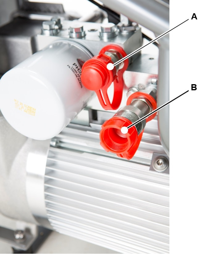
A | High pressure connector (Advance ) | B | Low pressure connector (Return) |
Lay the hoses in a way that they are not too tight or stretched, subject damage, and out of the passing vehicles area. Always respect the minimum radius of curvature of the hoses (a minimum of five times its nominal diameter).
The unit is supplied ready for use with the exception of the hydraulic oil. Before every use, make sure it has the adequate amount of oil in the reservoir. If necessary, top it up only with oil of the recommended characteristics (see chapter IV-2), always respecting the minimum and maximum levels indicated (see chapter III-3). Wear protective gloves, eliminate any spillage immediately and clean the surfaces with degreaser.
Use the hoses and connection elements of the recommended characteristics and without any wear and tear (worn exterior coat, bents, deformed, worn out or rusty connectors, etc).
Operation
Operating Instructions
Operating instructions
ALWAYS check the general state of the equipment before connecting it to the main, to detect possible damages, both in the unit and in the hydraulic circuit.
Verify that the hydraulic circuit is properly closed and that the tightening devices are correctly placed on the bolts to be tightened. Check that the personnel involved in the tightening process is alert and has the tools and the adequate personal protective equipment.
Connect the equipment to the main supply. Note that when using an autonomous generator unit, it should provide a minimum of 16 KVA power. Refer to the section MAIN SUPPLY REQUIREMENTS for details. Ensure that the emergency stop switch is released.
Select automatic or manual mode by pressing the grey button.
Operating in AUTOMATIC mode
The first time you choose the Automatic Mode (while the pump is not unplugged), a short message is displayed in the screen.

The system asks you to choose the learning cycle, for the pump to match with the wrench that is currently connected.
Connect the hose and the wrench properly. Press the green button to start the pump & then raise the pressure. Set the working pressure (manipulating the pressure regulating valve), according to the conversion chart and the model of torque wrench. Turn the regulating pressure valve counterclockwise, to ensure that at the start up moment the pressure does not raise to an undesirable value
Once the working pressure has been set, follow the instructions in the display to perform the “learning cycle”, by pressing the red button.

First, place the wrench that is connected to the hose in a safe place on the floor. After pressing the red button, the pump will perform the learning cycle by itself. The user could notice that the piston of the wrench moves up and down, reaching the max pressure set.
After the learning cycle is fully accomplished, the display will show the following message:

The text AUTO indicates that the pump is ready to work in Automatic Mode.
Now place the wrench over the bolt to be tightened. Press & hold the green button to initiate the tightening cycle. The pump will control the movement of the piston until full torque has been reached. The pump stops when the tightening cycle is finished. During last cycle, the wrench applies the maximum pressure for 2 - 4 seconds to secure an optimal torque and load transmission.
When the bolt is been tightening in automatic mode, the user of the pump must not release the green button before the tightening is completed.
Once the pump detects that the nut is tightened, the tightening stops automatically and the pressure falls to 0 bars. Now, the next bolt can be tightened.
Operating in MANUAL mode
Select Manual Mode by changing the automatic / manual mode button on the pendant. This message is displayed in the screen.

Connect the hose and the wrench properly. Press the green button to start the pump. Press it again to set the working pressure while turning the pressure regulating valve. Do this until you reach the desired working pressure according to the conversion chart and the model of torque wrench.
Now place the wrench over the bolt to be tightened. Press the green button to perform as many tightening cycles as needed, like any other “manual” torque pump.
If the Automatic Mode was set and as long as the pump is not unplugged, we can change between Automatic and Manual mode with the grey button.
It is important to note that if the hoses are changed or the wrench is unplugged, WE WILL HAVE TO REPEAT THE LEARNING.
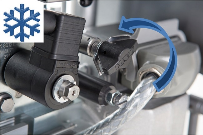
Cold start mode
In environmental temperatures lower 0 ˚C, to improve the start up the pump, press and hold the green button in the pendant. After 3 seconds, the pump will begin automatically a serial of start up - stop cycles. Hold green button until the pump starts up normally.
Service
Maintenance Instructions
Oil specification
The behavior “In-service” of a hydraulic equipment heavily depends on the quality and characteristics of the hydraulic fluid selected. The choice of the specification and viscosity of the hydraulic fluid should be based of the conditions of use, taking into account several factors as follows:
The range of environmental temperature.
The range of oil viscosity defined for the equipment.
The application (for example: range of pressures, sources of contamination of the hydraulic fluid, the type of pump).
The ease of getting a proper replacement or equivalent hydraulic liquid.
General concept
Before any intervention, unplug the pump from the main and make sure that the equipment cannot be switched on accidentally. Depressurize the whole hydraulic system prior to any disassembly.
Oil change intervals
Portable hydraulic equipment are susceptible to contamination due to the extreme conditions in which they work. Although selected fluids are designed to suffer less degradation than another product, we recommend an oil change and filter at least every 750 hours of use, or once a year, whichever occurs first.
It is recommended to periodically check the color of the oil and level seeking extreme contamination or loss of oil level that will require to refill the tank.
For oil changes or refilling, it is always recommended to use the same oil in the pump.
In case of an emergency and having to refill the tank and mix different types of fluids, it is preferred to use fluids with no additives as the HL or HLP fluids. After that, and always before a period of 2-4 working days, replace the oil with recommended oils.
Service Recommendations
Preventive maintenance is recommended at regular intervals. See the detailed information on preventive maintenance. If the product is not working properly, take it out of service and inspect it.
If no detailed information about preventive maintenance is included, follow these general guidelines:
Clean appropriate parts accurately
Replace any defective or worn parts
Hydraulic fluids
In general, hydraulic fluids recommended for this kind of portable hydraulic equipment should be manufactured under the following specifications:
AFNOR NF E 48-603 HV
ISO 6743/4 HV
DIN 51524/ P3 HVLP
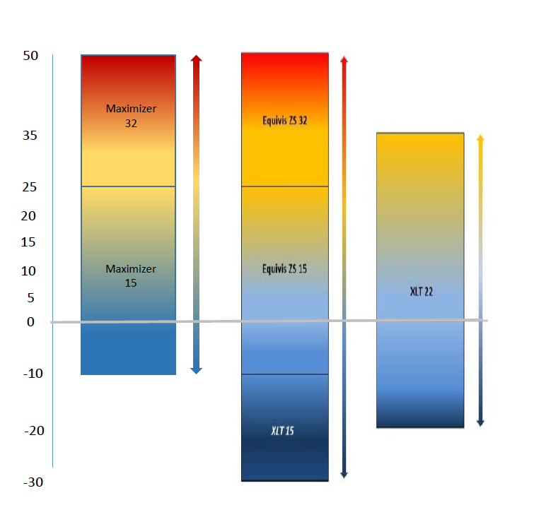
It is always recommended to use fluids with a high viscosity index fluid (I.V. > 140) to ensure a good stability under a wide range of temperatures.
The Atlas Copco Maximizer range of hydraulic oil meets the criteria as mentioned above, always choose the grade of oil as per environmental temperature. refer below given chart for the hydraulic oil selection
For Arctic Climates, we recommend a fluid as the TOTAL XLT 15, that allows good start-up bellow -20ºC.
For applications with critical conditions of service, environmental restrictions, or similar, please contact Atlas Copco to select the appropriate hydraulic fluid for each service.
For more information about hydraulic fluids, refer to:
Troubleshooting
Maintenance and conservation program
The checking and operations maintenance program depends on the equipment working conditions, so the frequencies indicated here are only an orientation and it is for the user to adapt them to the conditions of use.
Frequency | Verification / Task to be carried out |
|---|---|
Prior to each use | Check oil level in the tank is between maximum and minimum indicators. Set zero pressure and 100% pressure and check for noise (absence of friction, tapping, etc.) Check for leaks when the pressure is 150 bar. |
Monthly | Check that the unit reaches the maximum pressure. Check condition of power cable, free of erosion, joints, etc. Check hydraulic hoses and couplings. Replace if It is damaged. |
After 100 hours of use | It is recommended to perform a complete maintenance check. Consult authorized service centres, supplier or manufacturer directly. |
Total hours of use by the pump and maintenance hours from last maintenance can be seen as follows:
In the main screen press & hold the “ESC” and “down” arrow. The language screen is shown.
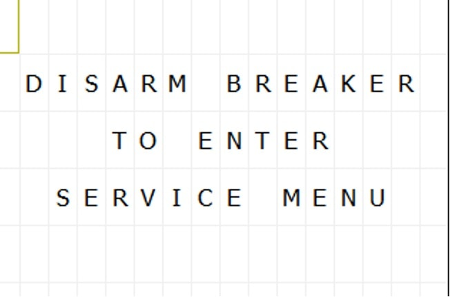
To continue in the menu, press & hold the “ESC” and “down” arrows again. If the breaker is up, the display will show a message: “disarm breaker to enter service menu”.
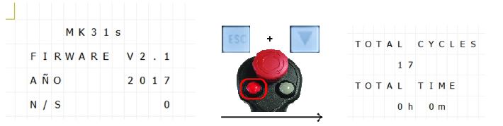
Once the breaker is disarmed, the screen shows information about firmware. Press & hold “ESC”+”down” arrow + “RED button” in the handgrip. Now, total hours and cycles is showed.
If you continue press “ESC”+”down” arrow, you can see maintenance counter since last maintenance, oil filter counter and oil counter.
To go back to the main screen, press “ESC”+ “UP” arrow several times.
Automatic Mode Causing Erratic Wrench Behaviour
Occasionally erratic wrench behaviour can occur if certain system conditions exist and the system can stop the wrench before the tightening has completed.
If erratic wrench behaviour is experienced carry out the checks below:
Oil temperature is too low : To overcome this issue remove the wrench from the bolt being tightened and place on the floor so it is free running. Switch the pump to manual mode, set the pressure to maximum (10000psi/690 Bar), then cycle the wrench back and forth allowing the pressure to build to maximum each time. Note: 10-15minutes of manual cycling may be necessary depending on environmental conditions. After the oil temperature has increased switch into Automatic mode, set working pressure, carry out learning cycle and attempt to tighten using automatic mode.

10-15minutes of manual cycling may be necessary depending on environmental conditions. After the oil temperature has increased switch into Automatic mode, set working pressure, carry out learning cycle and attempt to tighten using automatic mode.
If the erratic behaviour still exists it is possible that the oil grade is incorrect for the conditions. Try changing the oil to a more suitable grade for the working conditions.
Mixture of Coupling Brands : Although many screw-to-connect couplings claim to be interchangeable there are small internal differences that can cause unstable flow characteristics. This can cause the wrench operation to appear slow and cause the automatic mode to malfunction. To prevent these issues it is recommended that the couplings on the wrench, pump and hoses are all the same model and make.
Old Firmware Installed : Check Firmware number and contact Atlas Copco. If the problem persists fine tuning can be performed to suit specific system conditions, contact Atlas Copco for further advice.
Hydraulic Pump does not raise the pressure
Check that the pump is properly connected to the main supply.
Check that there is no sign of alarm in the control box.
Check for leaks in the circuit.
Check if right oil is used as per ambient temperature.
If the pump does not raise the pressure, contact local Atlas Copco sales representative.
Hydraulic unit does not start
Verify that the hydraulic unit is properly connected to the main supply and that the hydraulic fluid level is correct.
Verify that the Emergency Stop Switch is not pressed.
Verify that the power of your generator (if used) is sufficient and that the section of cable is suitable for the length of it. (See chapter II-3).
As a good practice, it is always recommended perform the starting of a hydraulic device without pressure. Pay attention that if the working conditions are below 10˚C or cable length is very long, you should open the regulating pressure valve to start the pump.
Temperature alarm is activated
After a very intensive use, the unit may suffer an excessive increase in the hydraulic fluid temperature, accentuated if the fall of potential in the supply line of the equipment is over 5%. In that case (reaching 80° C) turn off the unit and let it cool. Once the temperature of the unit falls, proceed as usual.
Oil level alarm is activated
Verify that the hydraulic liquid level is in between the maximum and minimum levels.
Min level | Max level |
|---|---|
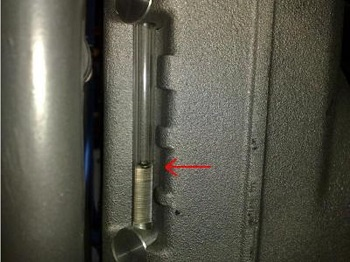 | 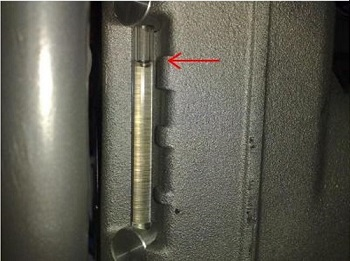 |
Automatic mode fails
In case of you detect any strange behavior of the wrench, a new learning cycle could be performed to adapt the pump to the new working conditions (oil temperature, length of hoses etc.) or simply due to a microcontroller disprogramming. Simply unplug and plug the pump in again to reset the memory and perform the learning cycle again.
Also there is a power switch on the left side of the control box that can be operated to restart the controller instead of unplug/plug the pump:

Change hydraulic oil
It is recommended to change hydraulic oil to 750 operation hours or one year depending on what occurs first.
First, remove the filler cap and then loosen the two cap screws, both at the bottom of the tank, with an Allen key. Once you have drained all the oil, place the screws back.

If you detect that oil presents a dark color, foam or particles, you must change oil and oil filter immediately. This can produce a fail in the unit.
Pay attention characteristics of oils and in case of doubt contact the manufacturer.
Change oil filter
It is recommended to replace oil filter every oil change
Unscrew the oil filter (A) by turning counterclockwise. Then, grease the joint of the filter and screw the new filter clockwise.

Change operating language
To change the operating language of the pump, the pump must be connected to main supply but with the motor turned off.
Language change in the PLC:

Press simultaneously “ESC” + down arrow. |  |
Press simultaneously “ESC”+ right arrow to see language in English. |  |
Press simultaneously “ESC” + up arrow to return main screen. |  |
SP Firmware update
To get the optimum performance from our new SP700 smart pump, we have introduced a software upgrade which is available on marketing and support portal to download from the product news section. You need to copy this software on a micro SD card and follow below procedures.
Software update procedure
Tools required
2.5 mm allen key
Flat face small screwdriver
Micro SD card with new software file only. Do not change name or add any other file in card
Card fits with label printing facing downward and contact points upward
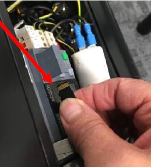
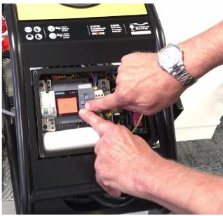
Open the control box. Pull off the tray bay to get the access to the memory card slot
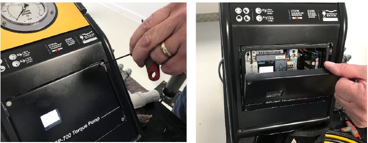
Insert the micro SD card and close the tray
Insert the micro SD card with print label faces down

Switch off the pump and unplug it from main supply

Switch on the pump
The firmware is automatically updated during the starting process. you can remove the micro SD card.
Check if new software has been uploaded successfully
Keep power on then put the breaker switch down in off position

Press Esc + Down arrow buttons together
Check the new FIRMWARE version installed in display, to go back to main menu, press ESC + UP arrow together

In case you find the FIRMWARE is still the old version then either it was not installed properly or your file is an old version. You can open file on your PC with MS Notepad and scroll right to see the Firmware version. Latest version is 2.5.
Alarms
The SP-700 pump is equipped with a display which shows following alert messages and the machine status:
At start
At the start-up moment of the pump, the mains screen shows the following information:
Pump model
Atlas Copco web page
Working
When the pump is working, several different alarms can appear which are described below.
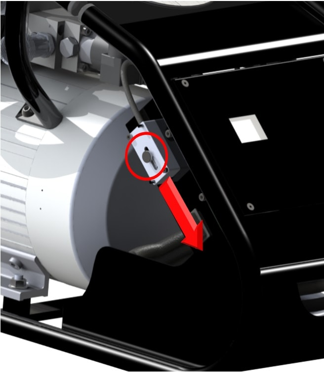
Current supply fault

A safety switch protects the control and the motor. If there is a severe current supply fault, the switch turns off. In this case, you can rearm with a system installed in lateral of the control box (see picture). Pull down the knob of this system to rearm the breaker.
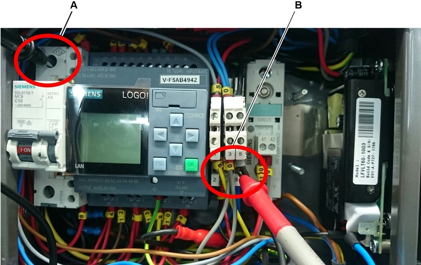
If there are 5 current supply fault alarms in less than 5 minutes, the display shows the following message during 5 minutes. Check voltage between terminal 6 and input breaker before working.

Temperature

Immediately turn off the pump and wait for it to cool.
Oil level

Check the oil level and fill it if necessary.
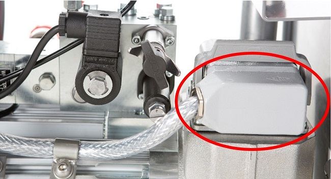
Oil and temperature level

If this alarm is showed in the display in control box, check if the harting connection is disconnected. If this connection is correct and the message does not disappear, contact the Atlas Copco service team.
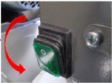
Emergency button

The emergency button in the control handgrip is pressed. To release turn it clockwise.
Oil service
After 750 operation hours from maintenance, a message in intermittent red screen is showed in the display when the pump is connected to the main supply: “Oil Service”. Change the oil and the filter of the pump.
Recycling
Environmental Regulations
When a product has served its purpose it has to be recycled properly. Dismantle the product and recycle the components in accordance with local legislation.
Batteries shall be taken care of by your national battery recovery organization.