Description
The SP-700 is a portable and automatic hydraulic unit for tightening bolts by a torque process. It allows reaching pressures up very fast which means a significant time saving in assembly operations. The SP-700 must only be used for the purpose for which it is intended and not for other purposes not listed in this manual.
The main idea behind its development is to reach the greatest grade of simplicity for the user, get a modular design, and great robustness in performance. It reflects the knowledge gained in microelectronics, design of control systems, hydraulics and mechanics through recent years. The SP-700 is the pump that achieves effectiveness in all areas related to product life: low maintenance costs, great increases in productivity, and energy savings, resulting in controlled costs during product life.
The SP-700 can be used in manual mode or in automatic mode. In the manual mode, the user activates the solenoid valve by pressing the green button of the pendant to initiate the movement of the piston. In automatic mode, the control of the pump operates the solenoid valve to initiate the movement of the piston with no intervention of the user. With the new algorithm, the pump detects when the piston have reached full stroke, and activates the retracting movement immediately.
To work in automatic mode, it is necessary to perform a learning cycle that it´s carried out in an autonomous way. By doing these cycles, the pump recognizes the hydraulic behavior of the wrench, no matter the size of the tool or even the manufacturer, memorizing the main parameters to let the algorithm take control of the pump.
The hydraulic pressure group is a compact electro mechanical kit, developed to facilitate the use in different sites and maneuverability, which consist of the following parts:
Submerged electrical motor
Gear pump
Directional solenoid valve
Manifold and secondary solenoid valve
Pressure gauge
Remote control handgrip
Control box
Protective steel frame
Hydraulic oil tank
Pressure regulating manual valve
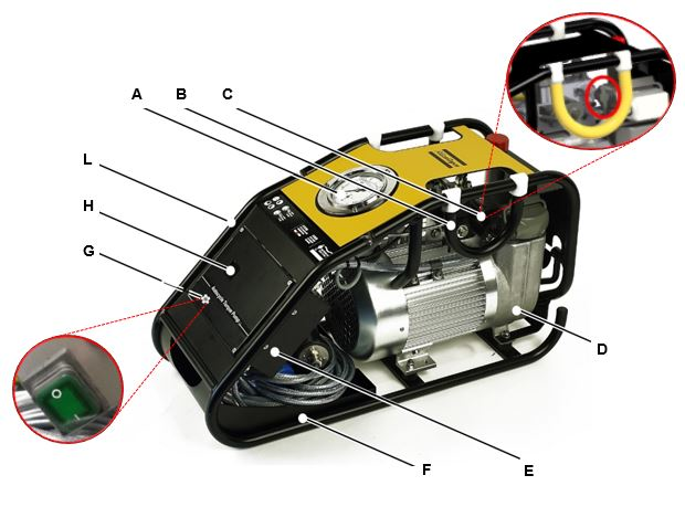
A | Pressure gauge | B | Carrying handle |
C | Regulating pressure valve | D | Oil tank |
E | Control box | F | Cable rack |
G | Main supply switch | H | Display |
L | Hose connectors |
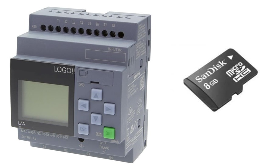
A PLC manages the control of the whole system. It is installed inside of the control box.
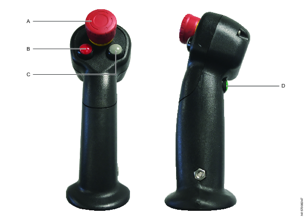
A | Emergency stop switch | B | Stop and pressure release button |
C | Automatic / Manual mode button | D | Start and pressure rise button |


