Industrial Location Guidance (ILG) (2.0)
Software
Introduction
In this section, you can find the basic information about the product and also the formatting conventions used in the topics.
General Description
Industrial Location Guidance (ILG) is the perfect tool to ensure consistent production quality and throughput. ILG is an integrated, stand-alone error proofing system that offers high-level process security for applications ranging from simple to complex. It tracks the exact location of the tool relative to the desired fastening position, ensuring the correct fasteners are tightened to specification, in the proper sequence. Comprised of ILG software, positioning hardware and tightening controller, the system combines the functionality of a tightening system with position and process control.
Features
Provides tightening data based on location
Provides assembly traceability
Configurable reject management
Configurable user interface
Tightening positions with start and finish
Visual indicators for status and feedback
Reject management – rework workpieces offline
Benefits
Production quality through process security
Less rework and scrapped parts
Clear diagnostics
Increased productivity
Intuitive design for easy start-up
General Data Protection Regulation (GDPR)
This product offers the possibility to process personal identifiable information such as system user name, role and IP-address. The purpose of this processing capability could be to enhance quality control through traceability and proper access management.
If you decide to process personal data you need to be aware of and comply with relevant personal data protection rules, including, in the EU the GDPR as well as other applicable laws, directives and regulations. Atlas Copco can in no way be held liable for any use made by you of the product.
Conventions
To enhance user understanding, certain formatting conventions are used throughout this document. The formatting conventions used are listed below.
Element | Notation | Description | Output |
|---|---|---|---|
General emphasis | In the Program workspace. | To make certain text elements stand out, or to highlight. | Text in Bold |
Graphical User Interface (GUI) items | Select the Function button. | Any reference to items found on screen in the GUI (for example, command buttons, icon names and field names). | Text in Bold |
Graphical User Interface (GUI) Path > | Generally, on the top of the GUI. | Navigation aid which keeps track of the location in the GUI. | For example: Controller > Program > Edit |
User input | Enter a Description for the program. | Any text input by the user. | Text in Bold |
File names | Enter a File Name for the export. | Files either exported from, or imported into the system. | Text in Bold Italic |
Variable and parameter names | Enter a Name for the export. | Variable and parameter names (not values). | Text in Italic |
Variable and parameter values | Enter a VALUE for the export. | Variable and parameter values. | Text in BOLD CAPS |
System output | Client.Domain.Models.ExportImportConfiguration | Any text output by the system. | Text in Monospace |
External links | Links to external sites that have information connected to the document or subject content. These could include:
| Selectable text to external sites | |
Internal documentation links |
If available, these links will be presented below the text. | Selectable text to internal content |
Liabilities and Warnings
Liability
Many events in the operating environment may affect the tightening process and shall require a validation of results. In compliance with applicable standards and/or regulations, we hereby require you to check the installed torque and rotational direction after any event that can influence the tightening result. Examples of such events include but are not limited to:
initial installation of the tooling system
change of part batch, bolt, screw batch, tool, software, configuration or environment
change of air- or electrical connections
change in line ergonomics, process, quality procedures or practices
changing of operator
any other change that influences the result of the tightening process
The check should:
Ensure that the joint conditions have not changed due to events of influence.
Be done after initial installation, maintenance or repair of the equipment.
Occur at least once per shift or at another suitable frequency.
Safety Signal Words
The safety signal words Danger, Warning, Caution, and Notice have the following meanings:
DANGER | DANGER indicates a hazardous situation which, if not avoided, will result in death or serious injury. |
WARNING | WARNING indicates a hazardous situation which, if not avoided, could result in death or serious injury. |
CAUTION | CAUTION, used with the safety alert symbol, indicates a hazardous situation which, if not avoided, could result in minor or moderate injury. |
NOTICE | NOTICE is used to address practices not related to personal injury. |
About the User Guide
The Industrial Location Guidance (ILG) User Guide gives all the operations of the Industrial Location Guidance (ILG) system: from initial system configuration to daily operations.
For a successful customer experience, execute the steps to procedures completion described in the ILG User Guide while working in the ILG software.
Industrial Location Guidance (ILG) is an integrated, stand-alone error proofing system that offers high-level process security for applications ranging from simple to complex.
ILG tracks the exact location of the tool depending on the fasteners position, making sure that the correct fasteners are tightened in the correct sequence. ILG system combines the functionality of a tightening system with position and process control.
The ILG system consists of:
ILG software
Positioning hardware
Tightening controller
Industrial PC (optional, depending on application)
The ILG service receives the data in real time from the positioning hardware sensors to calculate the tool location in three-dimensional space. Once the tool is located in the specified position, the ILG service selects the tightening program and enable the tool through Open Protocol.
Visual indicators - such as Stacklight, tool LED, or HMI process screen - tell the operator to initiate the tool start.
The positioning hardware includes high precision rotary or linear position sensors that are integrated into the pivot joints or linear guides of a torque arm or similar applications. The sensors connect with the tightening controller or the Industrial PC via a gateway module.
The gateway module communicates with the ILG service through Modbus TCP protocol.
Camera base ILS sensors are available too.
The ILG service communicates with the tightening controller through Open Protocol.
Multiple Atlas Copco tightening controller models are compatible with the system. Different positioning hardware configurations are available to suit the different arm types.
Revision History
Release Number | Revision Date | Revision Description |
|---|---|---|
item | item | none |
2.0 | 12/2022 | First official release of the Industrial Guidance Location (ILG) User Guide. |
System Overview
Hardware Structure
It is possible to set up several possibilities of the ILG software because of the high modularity and flexibility of the ILG software. Different connection structures can be used, depending on the requirements.
Controller Connected To Positioning System
The controller and the positioning system are directly connected through TCP/IP. The controller and the positioning system use the normal Ethernet connector of the controller.
This setup uses the Embedded ILG software version running on the controller.
It is possible to have one or more positioning system connected to the same controller. Example setups:
ILS Sensor connected to the controller.
Arm Position System connected to the controller.
ILS Sensor and Arm Position System connected to the controller.
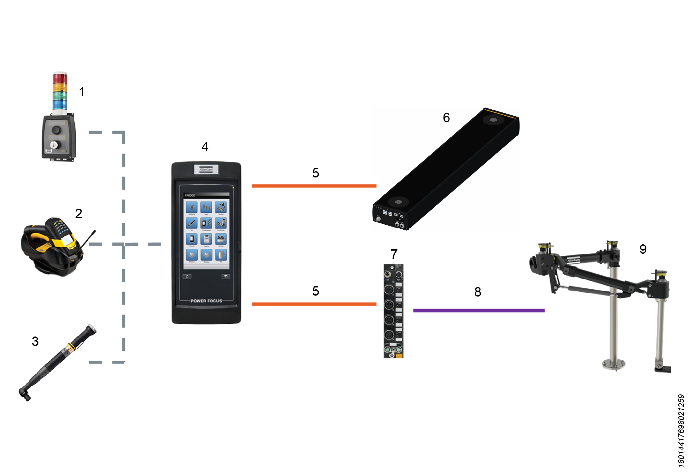
1 | Stacklight | 6 | ILS Sensor |
2 | Barcode Scanner | 7 | Sensor Gateway |
3 | Tool | 8 | Analog / IO Link |
4 | Controller | 9 | Arm Position System |
5 | TCP/IP over Ethernet |
Industrial Personal Computer Connected over Network to Controller and Positioning System
The tightening controller, sensor gateway and Industrial Personal Computer (IPC) are connected (by Ethernet) to a network.
All devices must be in the same TCP/IP Subnet (for example 192.168.0.XXX).
It is possible to have one or more positioning system connected to the same controller. Example setups:
ILS Sensor connected to the controller.
Arm Position System connected to the controller.
ILS Sensor and Arm Position System connected to the controller.
Multiple ILS Sensors connect to the controller.
This is called a Multi Sensor Solution
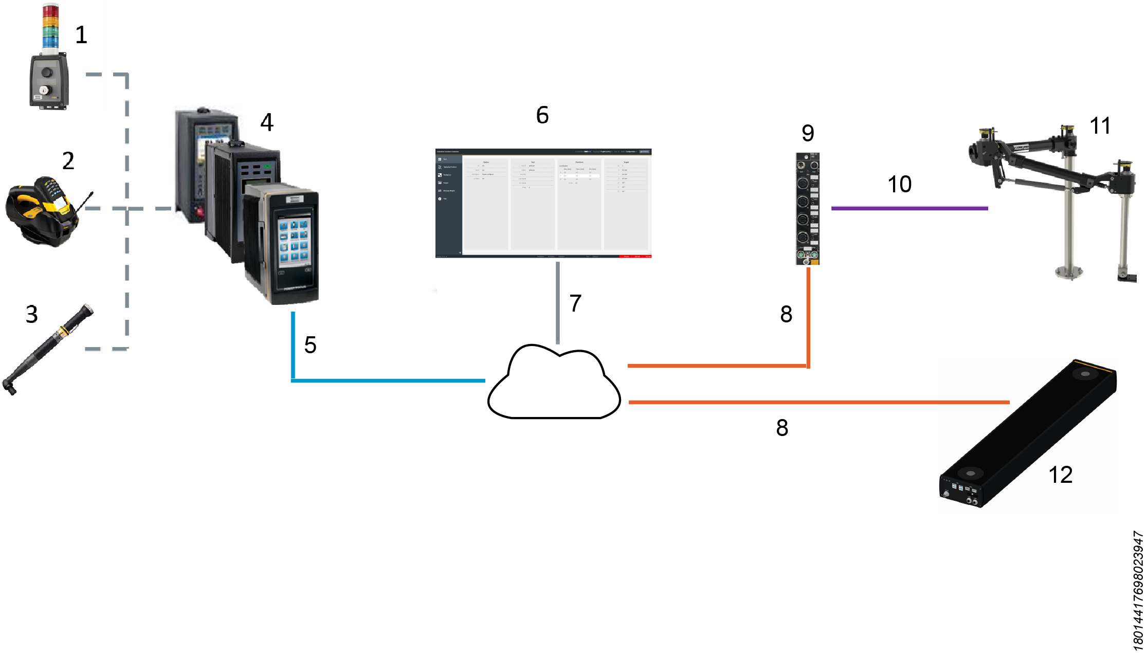
1 | Stacklight | 7 | TCP/IP |
2 | Barcode Scanner | 8 | TCP/IP |
3 | Tool | 9 | Sensor Gateway |
4 | Tightening Controller | 10 | Analog / IO Link |
5 | Open Protocol TCP/IP | 11 | Arm Position System |
6 | IPC - ILG HMI | 12 | ILS Sensor |
Software Structure
There are two versions of the ILG software; Embedded and HMI. The Embedded version runs on a controller and the HMI version runs on an external IPC.
For the configuration of the ILG software, and also for daily operations, a Graphical User Interface (GUI) is needed.
If using the HMI version, it is possible to use the screen of the IPC.
If using the Embedded version, connect a computer to the controller to make a TCP/IP connection.
In any case, it is possible to get to the GUI of the ILG software only through the web interface.
ILG Toolbar

ILG software toolbar is a grouping of commands which are optimized for efficient access.
On the left side of the ILG toolbar, the name of the software - Industrial Location Guidance - appears.
On the right side of the ILG toolbar, it is possible to see the connection status. Besides, it is possible to select the software language, the tool which the user can work with, the mode, and the user role.
Connection Status
On the right side of the ILG toolbar, the connection status shows 4 circles icons.
The first circle icon gives the connection between the User Interface (UI) and the ILG back-end through REST-API.
The second circle icon gives the connection between the User Interface (UI) and the ILG back-end through WebSocket.
The third circle icon gives the connection between the ILG back-end and the sensors.
The fourth circle icon gives the connection between the ILG back-end and the tightening controller.
The connection is up only if the circle icon is white. If the circle icon is blue, the connection is down.
On the left side of the ILG toolbar, hover over the 4 circle icons to see the connection status.
Language
On the right side of the ILG toolbar, open the Language drop-down menu and select the necessary language.
The start language is based on the browser language settings. Change the browser settings to the needed language for best user experience.
Tool
On the right side of the ILG toolbar, open the Tool drop-down menu and select the necessary tool.
Mode
On the right side of the ILG toolbar, open the Mode drop-down menu and select one of the available modes: Configuration, Setup, Diagnosis.
The Mode drop-down menu shows also the names of existing Workplaces.
User Role
On the right side of the ILG toolbar, the active User Role is shown: Worker, Configurator, or Service. Select the icon to change between user roles.
The user roles can be configured in Setup mode.
Accessories
Accessories are additional elements of the ILG setup that enrich the user experience and make sure the fulfillment of some specific use cases.
The proper usage of the accessories usually requires that all elements - the ILG software, the tightening controller, and the accessories - are correctly configured.
A standard ILG setup does not require any accessory.
Stacklight
The Stacklight, in combination with ILG software, can be used for different tasks.
The main task is to inform the user about the progress of the process through visual and audible indicators.
The Stacklight input options can also be used to control ILG processes.
Configuring Visual Indicators
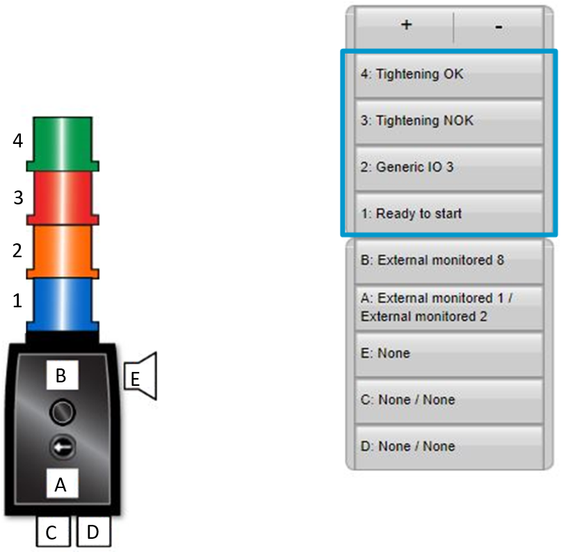
If you use the Stacklight in combination with ILG software, we recommend the following visual indicators configuration:
Operator information related to tightening enabled through the blue visual indicator: on the Home page of the controller, select Configurations > Stacklight > select Edit > select the blue lamp > set "Ready to start" as lamp signal.
Operator information related to OK tightening results: on the Home page of the controller, select Configurations > Stacklight > select Edit > select the green lamp > set "Tightening OK" as lamp signal.
Operator information related to NOK tightening results: on the Home page of the controller, select Configurations > Stacklight > select Edit > select the red lamp > set "Tightening NOK" as lamp signal.
Barcode Reader
The Industrial Location Guidance (ILG) software can be used in combination with a barcode reader for different tasks.
Installation and Upgrade
In this section, you can find information to help with the initial installation of the product, or upgrading from one version to another.
System Requirements
To install the Industrial Location Guidance (ILG) software on an industrial PC, the minimum system requirements are the following:
Processor: i3-6100
Memory: 8 GB
Operating System: Windows 10 or later
Web Browser Requirements
For optimal performance, use a web browser that has good JavaScript performance, and enable browser caching.
It is possible to run the software through the following web browsers:
Google Chrome 70 or later
Microsoft Edge 79 or later
Firefox 63 or later
Installing ILG Software
To install ILG software on the Industrial Personal Computer, run the full installation procedure.
Copy the setup IndustrialLocationGuidanceSetup<version>.exe to a known directory (for instance Documents) on the Industrial Personal Computer.
Double-click the executable program, and run the setup.
Agree to let the system be changed by the setup.
Read the license agreement carefully, and select I Agree.
Choose Automatic or Manual start, and select Next.
Choose Local only or Same network, and select Next. The default installation path appears.
Select Install, and wait until the installation is completed. The default web browser appears automatically at the end of the installation process.
As soon as the web browser shows the Industrial Location Guidance start page, select again the window of the installer. Then, select Close.
It is possible to connect to the Graphical User Interface (GUI) by browser on the Industrial Personal Computer - or any device connected to the same subnet.
Open a web browser and enter the IP of the Industrial Personal Computer followed by the port of the application (for instance, locally https://127.0.0.1:8181/, or remotely https://192.168.0.70:8181).
Wait a moment for the connection to become stable, and proceed with the further installation steps.
If ILG software runs on a controller, use the IP address of the controller.
If ILG software runs on the ILS Sensor, use the IP address of the ILS Sensor followed by the port of the application: https://192.168.0.80:8181. Replace the IP with your default setup IP of ILS Sensor.
Upgrading ILG Software
Before upgrading the ILG software, transfer the licenses.
To upgrade the ILG software on the Industrial Personal Computer, run the full uninstallation and installation procedure.
Copy the setup IndustrialLocationGuidanceSetup<version>.exe to a known directory (for instance Documents) on the Industrial Personal Computer.
Double-click the executable program, and run the setup.
Agree to let the system be changed by the setup.
Select Yes when asked to uninstall the previous version.
In the Uninstalling from box, enter the path of the previous version and select Uninstall.
When the uninstallation is complete, select Close.
Read the license agreement carefully, and select I Agree.
Choose Automatic or Manual start, and select Next.
Choose Local only or Same network, and select Next. The default installation path appears.
Select Install, and wait until the installation is completed. The default web browser appears automatically at the end of the installation process.
As soon as the web browser shows the Industrial Location Guidance start page, select again the window of the installer. Then, select Close.
Transferring a License
On the IPC, navigate to the installation directory of the ILG software. Usually C:\ProgramData\AtlasCopco\IndustrialLocationGuidance.
Move the amencebhlhnpeshldlbwcjhbpfzphubc and amzhfpbjwcpyyudpuggpnwwbuuhnfchc files to a known directory, for instance Desktop.
Upgrade the ILG software.
In the installation directory, delete the auto-generated amencebhlhnpeshldlbwcjhbpfzphubc and amzhfpbjwcpyyudpuggpnwwbuuhnfchc files.
Move the amencebhlhnpeshldlbwcjhbpfzphubc and amzhfpbjwcpyyudpuggpnwwbuuhnfchc files to the installation directory of the ILG software.
Transferring a License Video
Configuration
In this section, you can find detailed information about how to create, modify, and verify product settings.
Working with Configuration Mode
Start Page
Station
The Station section shows the ID, Name, Description, and Location of the station.
Tool
The Tool section shows the details of the selected tool. Details shown are:
Tool ID
Status
Direction
Last Result
Job Result
P-Set
Positions
The Positions section shows the X, Y, and Z coordinates of the selected tool.
Target
The Target section show the ID and coordinates of the target.
Tightening Positions Page
The process configuration of the ILG software gives the tightening parameters of the individual components and the necessary fastener sequences. The process configuration is necessary to define the working methods and tightening tasks. During operations, the working instructions control the individual component tightening connections.
In the ILG standard configuration, the processing is performed in a workflow relying on defined workpiece models. The ILG software starts processing a workpiece when it receives an identifier string corresponding to an identification number configured for a workpiece model. The process ends usually when all the tightening positions configured for the workpiece are completed. Then, put the tool to the home position.
All other actions of the process configuration are performed through the Tightening Positions page.
The buttons at the top of the Tightening Positions page can be used to add new elements or make changes.
Add Group: adds a new group above the currently selected position. To add a group at the bottom, clear the check box related to a selected line in the table.
Add Position: adds a new position.
Edit: opens the editing menu for the selected group or position.
Delete: deletes the selected element.
Teaching: starts the teaching mode where a series of new positions can be re-taught or created through the deactivated tool, and pulling the tool trigger.
Reteach: sets the XYZ values of the selected position depending on the tool physical position.
Reteach Relative: uses the relative position for teaching - for example, with part target.
Cond. Geo. ON: activates the conditional geometry of this element.
Copy: lets the user to copy/duplicate the selected positions into a specified Group.
Paste: lets the user to paste the copied positions into a specified Group.
Up arrow key: moves the item around accordingly.
Down arrow key: moves the item around accordingly.
Left arrow key: moves the item around accordingly.
Right arrow key: moves the item around accordingly.
Programming the Tightening Processes
To create tightening processes, ILG software has no fixed programming sequence which must be followed.
Since very different process sequences and structures may be necessary, ILG software offers different methods to support the setup of processes. These methods are not exclusive and can be combined according to requirements.
In general, to set up a complete tightening process, the user must:
Create a process structure - Depending on the application, different groups and positions must be arranged within the tree structure to define the process flow.
Set up the general tightenings parameter - Each tightening process is regulated by different specifications, which are valid for several tightening positions. These setting options include, for example, the loosening strategy, the referencing method, or the reject management.
Define the enabling and disabling volumes - A tolerance volume is defined around each position that is tightened in the process, which controls the release of the tool. Only if the tool is within the tolerance volume of the position, the tightening tool is enabled.
Make the teaching of the tightening positions - The main task of ILG software is to compare the current tool position with the predefined nominal positions. This nominal value is stored as Cartesian coordinates in the positions during the teach process.
Creating a Process Structure
ILG software uses a tree structure - shown through the Tightening Positions page - to build tightening processes. This structure has three classes that can have different types, features, and characteristics.
Home class: defines the home position of the tool that in the ILG setting is used for process finish. It exists only 1 Home class for 1 station.
Groups class: always describes several positions and possibly other groups. Their task is to define a sequence for the subordinate positions and groups, and to set higher-level tightening parameters.
Positions class: defines a single tightening position with all parameters for that single position.
The Groups class is responsible for building the structure of the process flows.
The groups can be additionally divided into two different types:
Group Workpiece: the workpiece is the main group and represents one component variant of the user or one tightening process. The workpiece is the start point for each tightening sequence. Only one workpiece is used per process.
Group Level: a level is an extension of a normal group. It can run its own images for the process visualization.
A level is used when the Process / Workpiece has several tightening layers that cannot be visualized in one main picture or require different tightening sequences of the same part.
The construction of a tightening process must always start with the workpiece.
The workpiece can then be structured by making different groups, levels and positions. The user can make as many groups / positions into an existing workpiece group as it is needed. The elements can be put freely, depending on the application.
Properties of the Classes
It is important to know the different properties of the individual classes to design the optimal process structure.
The properties assigned to the Groups class are:
Group ID - only the ID of the Workpiece is also the process ID
Order
Loosening strategy
Reject management
Referencing
Images
The properties assigned to the Positions class are:
Position ID
Tightening programs
Coordinates
Enabling / Disabling volume
Geometry condition
ILG software visualizes the hierarchical structure - and thus the work sequence of a process - by moving the individual elements in the process list.
Creating a Workpiece
In the Configuration mode, on the Tightening Positions page, in the Tightening Positions list cancel the selection for all the existing elements. Then, select the Add Workpiece button at the upper-left corner.
Group pop-up window opens.In the Group tab, enter and select the group parameters:
ID: enters the unique identifier string of the group.
All IDs must be globally unique, so that no other group or position may have the same ID.Order: selects the tightening order inside the group, which can be Forced Order or Free Order.
Free Order: the operator is free to choose the tightening sequence (or order) of the positions.
Visual indication is given when the tool is in one of the specified tightening positions.Forced Order: the operator is not free to choose the tightening sequence (or order) of the positions.
The operator must follow the sequence which is defined by the ordering of the positions in ILG software – from top to bottom. Operator guidance gives a blue position indicator at the specified tightening position.

Within groups with a defined order, it is possible to create a group with another order. The program changes the order as soon as the corresponding subgroup has been selected.
Once the operator starts a tightening within a given group, all elements (tightenings and subgroups) of this group must be finished before moving on to another group of the same hierarchy level.
Type: the type is Workpiece by default. It is not editable.
Loosening: defines in which positions the ILG software allows the operator to perform loosening.
Select the necessary loosening setting.Forbidden: does not allow loosening at all.
Valid_positions: allows loosening in all valid positions.
Worked_on_positions: allows loosening in all positions, which have been worked on (OK or NOK).
Unsuccessful_positions: allows loosening in all positions with a NOK tightening result.
Last_position: allows loosening in the last position. If the last position has been loosened, it changes to the previous position, which thus allows loosening in reverse tightening order.
Keep tool running: controls if the tool that started in a valid tightening position is still enabled if the operator moves the tool outside of the position during the tightening.
We recommend to select false. Select true only for very special applications.Retries: selects how many retries are allowed for tightening positions.
Bypass a NOK: selects if a tightening position can be bypassed.
Tools: assigns the necessary tool to the Workpieces.
In the Image tab, enter and select the image parameters:
Image: selects the necessary image.
Image size: adjusts the width and height of the image for the process display.
Image rotation: to display a process graphically within ILG software, the alignment of the component image must correspond to the real alignment between tool and component. ILG software cannot change image files graphically. Thus, if the image is rotated to the actual process view, this rotation cannot be compensated automatically.
Use Image Rotation function to realign the image, in case of a deviation between the real and the displayed alignment.Transformation and Translation: the transformation matrix and translation are the methods to transform the real-world 3D coordinate into the workpiece image coordinate. The transformation is done through the matrix multiplication, which does the image axis transformation and scaling, and the translation, which adjusts the position. These values require only fine-tuning here, because normally both transformation and translation can be easily determined using the image referencing in the Workpiece page.
In the Advanced tab, enter and select the advanced parameters:
Workflow option (optional) - Require effective loosening: loosening is only counted, if the tool had a minimum torque during loosening.
Workflow option (optional) - Geometry condition: enables conditional segments in the geometry.
Workflow option (optional) - Part Target Id: enables dynamic part target referencing.
Referencing (optional) - Reference position 1-3: enter the IDs of up to 3 reference positions for workpiece referencing.
For more information about referencing strategy, see the paragraph Compensation for Variable Workpiece Location: Referencing Strategy.2P Referencing Axis: selects the rotation axis, around which the workpiece is rotated. Only used if 2-point referencing is used.
At the lower-right corner of the Group pop-up window, select Save.
Compensation for Variable Workpiece Location: Referencing Strategy
In many situations, the workpiece to be processed is located in a location which is not the one that the model - created, for example, after teaching the tightening positions - assumes. Those situations can occur because of the setup of the assembly line, or because of the operation made on a movable table. It is possible to configure ILG software to compensate the variable workpiece location compared to the ILG system, depending on the application.
The compensation functionality is called Referencing.
ILG software gives different options to set up the Referencing:
Static: the workpiece is introduced in the same location every cycle.
All the Reference Positions boxes on the Advanced tab of the Workpiece Properties dialog box must be empty.1-Point Referencing: the part is introduced in different linear locations. 1-Point Referencing let the part translate linearly across any axes: X, Y, or Z.
A typical example is the assembly line, where the workpiece stops on the station in slightly different positions.
To use 1-Point Referencing for the given workpiece model, enter the ID of 1 tightening position defined for the workpiece as the Reference Position 1 on the Advanced tab of the Workpiece Properties dialog box.
Thus, before any other operation on the workpiece, the operator must pull the tool trigger on this particular position.2-Point Referencing: the part is introduced in different linear locations and rotated around one axis.
A typical example is when the workpiece gets at the ILG station on a movable table.To use 2-Point Referencing for the given workpiece model, give the axis around which the rotation is expected. Then, enter the IDs of the 2 tightening positions defined for the workpiece as the Reference Position 1 and Reference Position 2 on the Advanced tab of the Workpiece Properties dialog box.
Thus, before any other operation on the workpiece, the operator must pull the tool trigger on these particular positions in the specified order.3-Point Referencing: the part is introduced in different locations along all axis. 3-Point Referencing let the part translate linearly and rotationally across any axes: X, Y, or Z - all 6 degrees of freedom.
To use 3-Point Referencing for the given workpiece model, enter the IDs of 3 tightening positions defined for the workpiece as the Reference Position 1, Reference Position 2, and Reference Position 3 on the Advanced tab of the Workpiece Properties dialog box.
Thus, before any other operation on the workpiece, the operator must pull the tool trigger on these particular positions in the specified order.
Setting Up the 3-Point Referencing Strategy
Setting Up the 3-point Referencing Strategy procedure works best if the 3 points are as far apart as possible in both coordinates of the geometrical plane.
In the Configuration mode, on the Tightening Positions page, select an existing workpiece in the Tightening Positions list. Then, select the Edit button at the upper-left corner.
Group pop-up window opens.In the Advanced tab, enter the IDs of 3 tightening positions defined for the selected workpiece as the Reference Position 1, Reference Position 2, and Reference Position 3 .
If a reference strategy is used for a workpiece, the process always starts with the referencing. At the beginning of the process, only the reference points on the workpiece appear. Only after the operator has captured all reference positions, the fastener positions are displayed and can be fastened.
Compensation for Variable Workpiece Location: Dynamic Part Tracking
When the workpiece to be processed is located differently from what is defined in the model created—such as in a moving line—the ILG software running on an ILS Sensor can be configured to compensate for this. This is called Dynamic Part tracking.
Setting Up the Dynamic Part Tracking
In the Setup mode, on the ILS Sensor page, add a part target.
In the Configuration mode, on the Tightening Positions page, add the Part Target Id of the part target.
Creating a Group or Level
In the Configuration mode, on the Tightening Positions page, in the Tightening Positions list select an existing workpiece. Then, select the Add Group button at the upper-left corner.
Group pop-up window opens.In the Group tab, enter the new ID. Then, select the necessary type - Group or Level.

All IDs must be globally unique, so that no other group or position may have the same ID.

Before making any other change, see the paragraph Creating a Workpiece for more information about group parameters, image parameters, and advanced parameters.
At the lower-right corner of the Group pop-up window, select Save.
Adding groups or levels is an optional step.
Many workpieces only need to have tightening positions without the need for intermediate hierarchy levels.
Configuring a Group
This video explains how to configure a group.
Creating a Position
In the simplest situation, a given workpiece model contains just tightening positions.
It is possible to add tightening positions to the workpiece through different procedures.
Manual Creation of the Tightening Positions
In the Configuration mode, on the Tightening Positions page, in the Tightening Positions list select an existing workpiece or group/level. Then, at the upper-left corner, select the Add Position button.
Position pop-up window opens.In the Position tab, enter and select the position parameters:
ID: enters the unique identifier string of the position.
All IDs must be globally unique, so that no other group or position may have the same ID.X / Y / Z: enters the physical location of the tightening position. This location is normally reused also to enable and to disable volumes and to calculate the image position in the workpiece view.
P-Set: enters the tightening parameter set, which is selected for this position.
Disabled:
Tools: assigns the necessary tool to the Position. No tools means all tools.
In the Volume tab, enter and select the volume parameters:

Each tightening position has a tolerance that let the tool operate within a so-called Enabling Volume area. A separate tolerance, called Disabling Volume area, is used to no longer allow the tool to operate.
Enabling Volume parameters: enable the tightening tool within the specified position.
Disabling Volume parameters: in addition to the Enabling Volume parameters, it is possible to give an upscale volume of the Enabling Volume parameters through the Disabling Volume parameters.

For more information about volumes, see the paragraph Volume Types.
In the Bolt tab, define the image position and bolt display radius in the image.
If these parameters are not specified, the image location is calculated from the workpiece transformation; besides, the radius is 10 by default.In the Advanced tab, enter and select the advanced parameters:
Reject Management
Retries: selects how many retries are allowed for tightening positions
Bypass a NOK: selects if a tightening position can be bypassed.
Coordinate System
Use absolute coordinate: mostly used for home position of tool. If needed, select to refer to a Cartesian System that uses x-axis, y-axis, and z-axis to establish a point some distance from a common origin.
Geometry Condition: the geometry condition identifier enables conditional segments in the geometry. Geometry conditions assigned in an individual position requires that the group containing this position is configured in a forced tightening order.
Position No.: if configured, sends back to the tightening controller.
At the lower-right corner of the Position pop-up window, select Save.
Repeat the Creating a Position - Manual Creation of the Tightening Positions procedure as many times as many tightening positions are needed.
Teaching and Copying
To add tightening positions to the workpiece through the Teaching and Copying procedure, it is mandatory that the workpiece model has already been created.
In the Configuration mode, on the Tightening Positions page, teach the tightening positions of the new workpiece model - for more information, see the paragraph Teaching New Workpieces.
Make sure that a new group is automatically created. The taught tightening positions are into the created group.
Copy the taught tightening positions into the necessary existing workpiece. Then, delete
Delete the new group that was automatically created and contained the taught tightening positions.
If needed, edit the parameters of the tightening positions.
Teaching and Renaming
To add tightening positions to the workpiece through the Teaching and Renaming procedure, it is mandatory that the workpiece model has already been created.
In the Configuration mode, on the Tightening Positions page, teach the tightening positions of the new workpiece model - for more information, see the paragraph Teaching New Workpieces.
Edit the parameters of the group to let it be a workpiece model.
Creating and Reteaching
In the Configuration mode, on the Tightening Positions page, in the Tightening Positions list select an existing workpiece or group/level. Then, at the upper-left corner, select the Add Position button.
Position pop-up window opens.Edit all the parameters of the tightening positions, but do not enter the coordinates X / Y / Z.
Repeat the Creating a Position - Creating and Reteaching procedure as many times as many tightening positions are needed.
Reteach all the tightening positions - for more information, see the paragraph Reteaching Single Positions.

Reteaching a single position is not a process, it is a one-time action, so it must not be finished specifically.
Volume Types
Sphere
Like a circle in a two-dimensional space, a sphere is defined mathematically as the set of points that are all at the same distance r from a given point in a three-dimensional space.
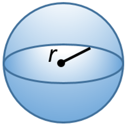
The radius defines the size of the sphere.
For example, in the Volume tab of the Position pop-up window, enter and select the Enabling Volume parameters. Select Sphere as volume and enter 15mm as radius. Then, select the Same as position check box.
The Disabling Volume parameters are programmed to an upscale percentage (20%): thus, the sphere radius is 20% bigger (18mm).
The tool is enabled when into the Enabling Volume parameters. The tool is disabled when is outside the sphere of the Disabling Volume parameters.
Then, the tool is enabled again only when moved back into the Enabling Volume parameters again.
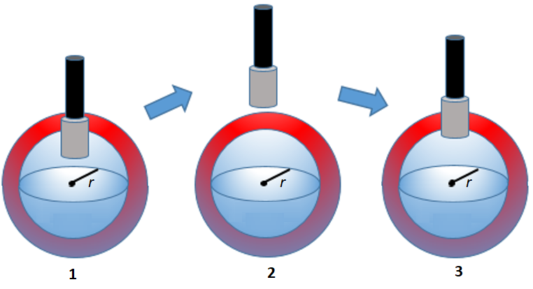
1 | Tool Enabled | 3 | Tool Enabled |
2 | Tool Disabled |
Cylinder
The cylinder has two identical flat circular ends and one curved side.
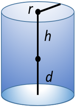
The radius, height, and depth define the size of the cylinder. These 3 dimensions typically originate from the X / Y / Z position. The direction of the cylinder must also be defined using a vector coordinate. Simple vectors - such as a straight vertical or horizontal cylinder - may be manually programmed.
For instance, setting X=0, Y=0, Z=1 gives a vertical cylinder.
Setting X=1, Y=0, Z=0 gives a horizontal cylinder:
|
|
Vertical cylinder | Horizontal cylinder |
Cone
The cone is similar to the cylinder, but the radius is different in length at each end.
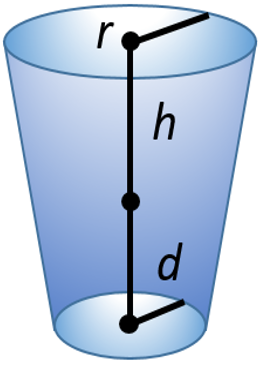
Configuring a Position
This video explains how to configure a position.
Teaching Process
In ILG software, the Teaching process causes a completely new tightening position along with the new related coordinates.
The Reteaching process causes an update of the coordinates of an existing tightening position.
In both cases, the physical position of the tightening tool is used.
During the Teaching process, nominal positions or target coordinates are assigned to the process model in ILG software. This process defines the geometrical model of a workpiece.
After entering the coordinates, ILG software enables tightening in the correct positions of the active workpiece. Thus, it is very important that the Teaching process is run under optimal conditions.
Before running the Teaching process, make sure that:
A real workpiece is in the system; the fastening conditions - workpiece geometry, fasteners, and so on - agree with the conditions in normal production.
The workpiece is optimally positioned in the workspace
The geometry of the tool is completely mapped within ILG software.
The fastening sequence of the components is known and is observed during the Teaching process.
The controller is configured and connected to the ILG software.
Teaching New Workpieces
The Teaching process of new workpieces is used for simple process setups, where only 1 workpiece exists. In this case, all the tightening positions are into the only existing workpiece.
If the process has a more complex structure, we recommend to create the workpiece and group structure. Then, perform the Teaching process for the existing groups.
In the Configuration mode, on the Tightening Positions page, in the Tightening Positions list cancel the selection for all the existing elements.
At the top of the Tightening Positions page, select the Teaching button. The Teaching pop-up window appears.
In the Teaching pop-up window, cancel the Reteaching selection.
Put the tool in the necessary tightening position. Then, press the tool trigger shortly.
After each trigger signal, a message appears.
Confirm the information on the successful teaching and move on to the next tightening position. Repeat this step for all the necessary tightening positions.
A possible warning about tool being disabled is not important as the teaching process does not require tightening.
At the top of the Tightening Positions page, select the Teaching button to stop the Teaching process.
For more information about how to edit the taught positions, see the paragraph Creating a Position.
If the Teaching process is repeated for several workpieces, the ILG software changes automatically the workpiece ID number, so that always only unique workpiece IDs exist.
Teaching Existing Workpieces / Groups
In the Configuration mode, on the Tightening Positions page, in the Tightening Positions list select an existing workpiece / group.
At the top of the Tightening Positions page, select the Teaching button. The Teaching pop-up window appears.
In the Teaching pop-up window, cancel the Reteaching selection.
Put the tool on the necessary tightening position. Then, press the tool trigger shortly.
After each trigger signal, a message appears.
Confirm the information on the successful teaching and move on to the next tightening position. Repeat this step for all the necessary tightening positions.
A possible warning about tool being disabled is not important as the teaching process does not require tightening.

The names of the positions are created by adding a consecutive number to the name of the workpiece / group. Thus, always define the workpiece / group names before the Teaching process.
At the top of the Tightening Positions page, select the Teaching button to stop the Teaching process.
Reteaching Existing Workpieces / Groups
Sometimes it is necessary to reteach already configured tightening positions. For example, this scenario can happen in case the geometry changes due to a new workpiece carrier. For these scenarios, existing groups may be taught again without changing the already set parameters.
In the Configuration mode, on the Tightening Positions page, in the Tightening Positions list select an existing workpiece / group.
At the top of the Tightening Positions page, select the Teaching button. The Teaching pop-up window appears.
In the Teaching pop-up window, select Reteaching.
Put the tool in the necessary tightening position. Then, press the tool trigger shortly.
After each trigger signal, a message appears.
Confirm the information on the successful teaching and move on to the next tightening position. Repeat this step for all the necessary tightening positions.
A possible warning about tool being disabled is not important as the teaching process does not require tightening.

The position coordinates in the group change according to the new positions.
During the Reteaching process, it is possible to change only the existing position in the given workpiece / group. Once reached the defined number of positions within the workpiece / group, pressing the tool trigger has no effect.At the top of the Tightening Positions page, select the Teaching button to stop the Teaching process.
Reteaching Single Positions
ILG software reteaches the coordinates of a single position, if needed.
This procedure must be run by 2 people: interaction both with the ILG software user interface and the tool is needed.
In the Configuration mode, on the Tightening Positions page, in the Tightening Positions list select an existing position.
Put the tool in the necessary tightening position. Then, at the top of the Tightening Positions page, select the Reteach button.

The position coordinates in the group change according to the new position.
Copying and Pasting
To make the assignment of tightening parameters easier, ILG software gives the possibility to copy parameters of a tightening position / group. The copied parameters can be moved to other groups.
Through ILG software, it is possible to:
Copy the complete position: creates a copy of the tightening position within the same group or another group.
Copy the position parameters: copies specific parameters of a tightening position. Thus, the copied parameters are moved to individual positions or to all positions within a group.
Copying the Complete Position
In the Configuration mode, on the Tightening Positions page, in the Tightening Positions list, select the position to be copied. Then, at the top of the Tightening Positions page, select the Copy button.
Copy Position pop-up window opens.Select Complete Position. Then, at the lower-right corner of the Copy Position pop-up window, select OK.
In the Tightening Positions list, select the necessary group into which the copied position must be copied.
At the top of the Tightening Positions page, select the Paste button.
The copied position appears at the bottom of the selected group.
Copying the Position Parameters
In the Configuration mode, on the Tightening Positions page, in the Tightening Positions list, select the position with the necessary parameters to be copied. Then, at the top of the Tightening Positions page, select the Copy button.
Copy Position pop-up window opens.Select the parameters to be copied. Then, at the lower-right corner of the Copy Position pop-up window, select OK.
In the Tightening Positions list, select a position or the necessary group into which the copied parameters must be copied.
At the top of the Tightening Positions page, select the Paste button.
The parameters of the selected position or of all the positions inside the selected group change according to the copied parameters.
Workpieces Page
The Workpieces page shows the position parameters with the selected image that is used with the selected workpiece, the tightening positions, and the position of the tightening tool in real life.
To make the Workipieces page running, it is essential to configure the graphical elements. Then, it is important to perform the Image Referencing for each of the workpiece models.
Selecting Workpiece Model and Image
Typically, the workpiece image uploaded into the ILG software needs a repositioning process to match the real situation at the workstation.
In the Configuration mode, on right of the Workpieces page, in the Workpiece drop-down menu select the workpiece model which needs to perform the image update.
In the Image drop-down menu select the image to be updated.
Rotating the Image
To display a process within ILG software graphically, the alignment of the component image must correspond to the real alignment between tool and component. ILG software cannot change image files graphically. Thus, if the image is rotated to the actual process view, this rotation cannot be compensated automatically.
If a deviation between the real and the displayed alignment happens, the Image Rotation feature, in the Workpieces page, gives the option to realign the image.
Use the Image Rotation feature always at the beginning of a graphical process representation. The image is rotated with the help of two interpolation points.
In the Configuration mode, on the right of the Workpieces page, select the Image Rotation button.
Move the cursor on the first image point that represents the real picture alignment. Then, select that location.
Move the cursor on the second image point that represents the real picture alignment. then, select that location.
The image rotates automatically around its own geometrical center.
Referencing Images
The Image Referencing feature let the user to scale and to put the workpiece image in the ILG software coordinate system. Through the Image Referencing feature, the tightening positions related to the workpiece model and the corresponding points on the workpiece image can be mapped onto each other.
To do the Image Referencing procedure, use the Workpiece page of the ILG software and the tightening tool.
In the Configuration mode, on the right of the Workpieces page, select the Image Referencing button.
The Image Referencing pop-up window appears.Select the geometrical plane in which the image is located.
Then, at the lower-right corner of the Image Referencing pop-up window, select OK.Put the tightening tool on a defined physical position on the actual workpiece model.
On the Workpiece page, move the cursor on an image location corresponding exactly to the position of the tool held on the workpiece. Then, select that location.
Repeat this step for a second and a third position.At the upper-right corner of the Workpieces page, select the Save icon.
The Image Referencing procedure works best if the 3 points are as far apart as possible and are arranged in a triangle in both coordinates of the geometrical plane, in which the workpiece image is located.
The Image Referencing procedure shows the correct tool position (crosshair) on the workpiece image, while the real tool moves over the real workpiece. Besides, the tightening positions of the workpiece appear as yellow points on the image, depending on the taught positions.
Moving the Tightening Positions
It is possible to find some distortions in the placement of the tightening positions, especially for bigger workpieces or for images that come from photos of workpieces (rather than technical drawings). This means that the crosshair of the tool placed in the defined tightening position, in reality, is not displayed on the tightening position on the image.
The Moving the Tightening Positions procedure moves the dots that are related to the tightening positions manually. The procedure affects only the display, and not the model.
In the Configuration mode, on the right of the Workpieces page, select the needed tightening position in the Bolts list.
At the bottom of the Bolts list, select Move.
On the image, move the cursor on the real bolt position. Then, select that location.
Repeat the Moving the Tightening Positions procedure as many times as many tightening positions need to be aligned with the image.
Images Page
The Images page shows a list of images already uploaded to the ILG software.
After selecting an image, on the right of the Images page, it is possible to see the preview of the selected image. Select the link at the bottom of the preview to automatically zoom in the selected image.
The buttons at the top of the Images page can be used to add, download, or delete images.
Refresh: refreshes the Images page.
Add: adds a new image.
Download: downloads the selected image.
Delete: deletes the selected image.
Uploading Images
In the Configuration mode, on the Images page, at the upper-left corner, select the Add button.
Modal pop-up window opens.Select Choose File. Open pop-up window opens.
Select the image to be uploaded to ILG software. Then, at the lower-right corner of the Open pop-up window, select Open. The Modal pop-up window shows the selected image.

Supported images formats:
PNG - Portable Network Graphics
JPEG /JPG - Joint Photographic Experts Group
GIF - Graphics Interchange Format
The maximum file size for images is 5MB.
At the lower-right corner of the Modal pop-up window, select Save.
The images list shows the uploaded image.
Deleting Images
In the Configuration mode, on the Images page, select the image to be deleted.
At the upper-left corner of the Images page, select the Delete button.
Message Mapper Page
The Message Mapper page shows a list of already created input and output messages.
The + button at the top of the Message Mapper page can be used to add messages.
Input Message
Type | Description |
|---|---|
Entered Position | Entering a position triggers this option. Choose a tool and a position to match. |
External monitored 1 to 8 | Triggers on external monitored I/O. Choose a tool, a group and the matching inputs. |
Left Position | Leaving a position triggers this option. Choose a tool and a position to match. |
Lock tool | Triggers on locking the tool by ILG (not by other sources). Choose a tool to match. |
Process result | The workpiece is finished. Choose a workplace and a result to match. |
Received VIN | ILG received a VIN through OpenProtocol. Choose a tool and a VIN to match. |
Release Tool | Triggers on releasing the tool by ILG (not by other sources). Choose a tool to match. |
Selected Pset | Refers to the pset, which is sent by the controller. Choose a tool and a pset to match. |
Workpiece Running | Triggers on start of a new workpiece. The chosen workplace and workpiece ID must match. |
Advanced | Is only for advanced users, who want to react on some other internal messages. |
Output Message
Type | Description |
|---|---|
Finish process | Ends the current workpiece gracefully, resulting in a process result message. Choose the affected workplace. |
Generic IO 1 to 10 | Set the state of one generic IO. Choose the tool, the relay ID and the state, which are to be used. |
Lock tool | Leaving a position triggers this option. Choose a tool and a position to match. |
Notify | Triggers on locking the tool by ILG (not by other sources). Choose a tool to match. |
Release tool | The workpiece is finished. Choose a workplace and a result to match. |
Reset process | ILG received a VIN through OpenProtocol. Choose a tool and a VIN to match. |
Start workpiece | Triggers on releasing the tool by ILG (not by other sources). Choose a tool to match. |
Advanced | Is only for advanced users, who want to react on some other internal messages. |
Message Mapping
This video explains how to set up input and output messages.
Help Page
Scan the QR code or select GOTO ONLINE HELP to open the Industrial Location Guidance (ILG) User Guide.
Working with Setup Mode
Workplaces Page
The Workplace page shows the status of the current running tightening process. Besides, it let the tightening process start.
Usually, the Workplace page guides the operator.
In the Workplace page, the operator can track the tool position with the crosshair on the workpiece image; thus, it is possible to follow the progress.
The Workplaces page shows the workplaces as a list.
The buttons at the top of the workplaces list can be used to add new workplaces or make changes.
Add: adds a new workplace to the workplaces list.
The system adds the new workplace at the end of the list automatically.Edit: opens the Workplace pop-up window for the selected workplace.
Delete: deletes the selected workplace.
Creating a Workplace
In the Setup mode, on the Workplaces page, select the + icon at the upper-left corner.
Workplace pop-up window opens.Enter the workplace ID and the workplace name. Then, select the tools to be linked to the workplace, and the necessary Workflows items.
Then, at the lower-right corner of the Workplace pop-up window, select Save.
Configuring a Workplace
This video explains how to configure a workplace.
Position Selection Method
Licenses Page
The Licenses page shows active licenses.
The buttons at the top of the Licenses page can be used to generate and upload licences.
GENERATE LICENSES REQUEST: generates a request for a new license.
UPLOAD LICENCE RESPONSE: uploads licenses from a file.
Generating a License
In the Setup mode, on the Licenses page, select GENERATE LICENSE REQUEST .
Select the Activation Code box and enter the activation code.
Select OK.
Uploading a License
Select Upload in the upper left corner of the licenses page.
Select Choose File and navigate to the correct license location.
Select Open.
The licenses list shows the uploaded license.
Restart the ILG software after uploading a license.
Tools Page
The easiest method to configure the Tools page of the ILG software is using the Assistant, which can be followed by manual adjustment.
Tool Tab
The initial configuration Assistant simplifies the basic configuration of the ILG software to set up the communication interface to the sensors and the tightening controller. At the beginning of any system setup, use the assistant to decrease the setup effort.
The buttons at the upper-left corner of the Tool tab can be used to make changes to an existing tool, or delete.
Edit: lets the user make changes to the selected tool.
Delete: deletes the selected tool.
Creating a Tool for ILS
In the Setup mode, on the Tools page, select the + icon at the upper-right corner.
Create a new tool pop-up window opens.In the OpenProtocol Connection window, enter the assistant.tool_id.
Then, select the Controller Type, and enter the Open Protocol IP of the selected tightening controller, and the OpenProtocol Port.
Then, at the lower-right corner of the OpenProtocol Connection window, select Next.In the Positioning window, select ISRA Vision SpotPoint 2.0 as measuring system.
Then, at the lower-right corner of the Positioning window, select Next.In the ISRA Vision SpotPoint 2.0 window, enter the Host and Port to connect to the ILS sensors.
Then, at the lower-right corner of the ISRA Vision SpotPoint 2.0 window, select Next.In the Tool Targets window, enter the Tag ID, and the value of X, Y, Z, rX, rY, and rZ, depending on where the tag is installed.
Then, at the lower-right corner of the Tool Targets window, select Save.
The Target ID is automatically set by ILG software.
The Target ID is 0 for the first tool. Then, it increases gradually by 1 unit every time a tool is added.
The Tag ID shows on each QR code.
Creating a Tool for ILS Video
Creating a Tool for Arm Systems
In the Setup mode, on the Tools page, select the + icon at the upper-right corner.
Create a new tool pop-up window opens.In the OpenProtocol Connection window, enter the assistant.tool_id.
Then, select the Controller Type, and enter the Open Protocol IP of the selected tightening controller, and the OpenProtocol Port.
Then, at the lower-right corner of the OpenProtocol Connection window, select Next.In the Positioning window, select Rotation / Linear sensors as measuring system.
Then, at the lower-right corner of the Positioning window, select Next.In the Geometry Type window, choose the geometry type.
Then, at the lower-right corner of the Geometry Type window, select Next.In the Sensor Configuration window, select the Sensor Module type and enter the Sensor Module ID.
Then, at the lower-right corner of the Sensor Configuration window, select Next.In the Sensor Assignment window, choose the X Rotation sensor, Y Rotation sensor, and Linear sensor. Enter the L1: fixed path length and the L2: maximum additional vertical travel distance.
Then, at the lower-right corner of the Sensor Assignment window, select Save.
Creating a Tool for Arm Systems Video
Tags Tab
The initial configuration Assistant simplifies the basic configuration of the ILG software to set up the communication interface to the sensors and the tightening controller. At the beginning of any system setup, use the assistant to decrease the setup effort.
The buttons at the upper-left corner of the Tags tab can be used to add a new tag to the tool. Besides, it is also possible to make changes / delete an existing tool tag.
Add Tag: adds a new tag to the tool.
Edit: lets the user make changes to the selected tool tag.
Delete: deletes the selected tool tag.
If the tool has more tags, add the missing tags through the Add Tag button.
Adding a Tool Tag
In the Setup mode, on the Tools page, on the Tags tab, at the upper-left corner select the Add Tag button .
Tool Tag pop-up window opens.Enter the Tag ID, and the value of X, Y, Z, rX, rY, and rZ, depending on where the tag is installed.


X:
Y:
Z:
rX:
rY:
rZ:
At the lower-right corner of the Tool Tag pop-up window, select Save
Editing a Tool Tag
In the Setup mode, on the Tools page, on the Tags tab, select the item to be edited.
At the upper-left corner of the Tags tab, select the Edit button. Tool Tag pop-up window opens.
On the Tool Tag pop-up window, change the needed parameters. Then, at the lower-right corner of the Tool Tag pop-up window, select Save
Deleting a Tool Tag
In the Setup mode, on the Tools page, on the Tags tab, select the item to be deleted.
At the upper-left corner of the Tags tab, select the Delete button. Delete Element pop-up window opens.
On the Delete Element pop-up window, select Yes.
Geometry Tab
The Geometry tab calculates the tool position. The ILG software uses a geometry model and ILS sensors to calculate the position of the tool in Cartesian coordinates. The result of the geometry is the tool position in X, Y, and Z.
Regardless of whether the configuration assistant is used or a completely new geometry is created, it is possible to make manual adjustments to the geometry to create a complete geometry.
For this purpose, ILG software gives an operating environment in the Geometry tab, which makes possible to set up geometries for all types of systems.
Creating the Geometry Model
When creating or adjusting the geometry model, always proceed beginning with the origin of the coordinate system, thus from the fixed suspension of the ILG hardware.
ILG software has three basic geometries for the creation or extension of a geometric model:
Fixed Segment: rigid element for describing fixed geometric elements.
Rotational Sensor: modeling of a rotational axis detected by an angle encoder or inclination sensor.
Linear Sensor: modeling of a linear axis captured by a linear sensor.
The geometrical model provides the three basic geometries in a given sequence.
The Geometry tab displays the geometry elements as a list.
The buttons at the top of the geometries list can be used to add new geometry elements or make changes.
Add: adds a new geometry element to the geometry list.
If you select an existing geometry element, the new geometry element appears in front of the selected geometry element.
If no geometry element is selected, the system adds the new geometry element at the end of the list.Edit: opens the editing menu for the selected geometry element.
Delete: deletes the selected geometry element.
Assistant: opens the initial configuration which simplifies the basic configuration of the ILG software.
If you select the Assistant button, the currently stored geometry elements and sensor configuration are removed.
Rotate: rotates the tool counterclockwise in any axis.
Cond. Geo. ON: activates the conditional geometry of this element.
Cond. Geo. OFF: deactivates the conditional geometry of this element.
How to Create a Geometry Model
In the Setup mode, on the Tools page, on the Geometry tab, at the upper-left corner select the Add button.
Add Segment pop-up window opens.Select the necessary geometry type.
Different configurations must be made, depending on the selected geometry type:
For a Fixed Segment:
Geometric expression of the element in millimeters (XYZ direction).
Color of the element in the geometric model: we recommend the usage of different colors for the neighboring segments.
For a Rotation Sensor:
Rotation axis of the sensor: the rotation axis of the sensor can be defined by 1 or 0 in the respective axis XYZ.
Rotation vector of the sensor: the direction of rotation is given by + or -.
Sensor: it says which of the installed sensors provides the measured values for the respective direction of movement.
Color of the element in the geometric model (if needed).
For a Linear Sensor:
Movement axis of the sensor: the movement axis of the sensor can be defined by 1 or 0 in the respective axis XYZ.
Movement vector of the sensor: the direction of movement is given by + or -.
Sensor: it says which of the installed sensors provides the measured values for the respective direction of movement.
Color of the element in the geometric model (recommended).
The geometry list shows all the geometry segments in a specific order. ILG software considers the exact order of the geometry segments during the operations. Add new geometry segments at the bottom of the list, after the default segments.
Model Tab
To facilitate and to validate the adjustment of the geometry, ILG software gives a 3D visualization of the tool geometry. The visualization consists of three screens, each showing a different viewing direction, able to capture every tool movement. The division of the viewing directions is determined by the three main planes of the coordinate system (X/Y, X/Z, Y/Z).
Real-time tool movement enables the user to validate the tool configuration is in the correct direction, and make sure that the rotation and movement is correct.
To get the full view of the tool model, select the Fit button, and the picture automatically scales to the actual tool position. The scaling in all three planes is independent from each other.
Changes in the configured geometry are immediately displayed in the Model tab. This real-time visualization makes possible to quickly verify the model and adjust movements between the geometric model and the real tool.
To validate the model, always make sure that the geometry is correct by moving the tool and watching the model on the screen. If a direction moves different than expected, then change the direction vector sign of the corresponding sensor entry.
Note that different elements of the model require different views for their verification. For example, a sensor that covers a vertical movement, cannot be verified by looking at the XY view. This is why ILG provides views in all three main planes of the 3D Cartesian system.
ILS Sensor Page
All configurations for using the ILG software with an ILS Sensor is available on the ILS Sensor page.
Controller Tab
The Controller tab shows the ILS Sensor configuration.
The button at the upper-left corner of the Controller tab can be used to configure the communication interface between the ILS Sensor and the ILG software.
Configuring an ILS Sensor
In the Setup mode, on the ILS Sensor page, on the Controller tab, at the upper-left corner select the Edit button.
Enter the host/IP of the ILS Sensor in the Host/IP box.
Enter the port of the ILS Sensor in the Port box.
Enter the master and slave IP.

If only one ILS Sensor is used, leave the Master name box and Slaves box empty.
Select SAVE.
Tool Targets Tab
The Tool Targets tab shows the targets and tags for the ILS Sensor tools.
The buttons at the upper-left corner of the Tool Targets tab can be used to add, make changes to, or delete an existing target or tab.
ADD TARGET: lets the user add a target.
ADD TAG: lets the user add a tag.
Edit: lets the user make changes to the selected target or tag
Delete: deletes the selected target or tag.
Part Target Tab
The Part Targets tab shows the targets and tags for the ILS Sensor parts. The tab is used when the assembly object is not in the same position relative the ILS Sensor.
The buttons at the upper-left corner of the Part Targets tab can be used to add, make changes to, or delete an existing target or tab.
ADD TARGET: lets the user add a target.
ADD TAG: lets the user add a tag.
Edit: lets the user make changes to the selected target or tag
Delete: deletes the selected target or tag.
Adding a Part Target
In the Setup mode, on the ILS Sensor page, on the Part Target tab, at the upper-left corner, select the ADD TARGET button.
Target pop-up window opens.In the Target window, enter a name for the part target.

The ID number will be automatically assigned.
Select SAVE.
Workspace Tab
The Workspace tab shows the targets and tags for the ILS Sensor workspace.
The buttons at the upper-left corner of the Workspace tab can be used to add, make changes to, or delete an existing target or tab.
ADD TARGET: lets the user add a target.
ADD TAG: lets the user add a tag.
Edit: lets the user make changes to the selected target or tag
Delete: deletes the selected target or tag.
Barcode Reader Page
The Barcode Reader page shows the configuration of the barcode reader.
The button at the upper-left corner of theBarcode Reader page can be used to change the configuration.
Configuring a Barcode Reader
In the Setup mode, on the Barcode Reader page, at the upper-left corner select the Edit button.
Enter the Baudrate, Post Characters, Pre Characters, and Serial Port of the Barcode Reader.
Select SAVE.
Security Page
The Configuration page allows for configuration of the user roles by setting and changing passwords.
Setting a Password
Select CHANGE PASSWORDS.
Choose the user role to change password for.
Enter the old password in the Old Password box.

Leave the Old Password box empty if no password has been previously set.
Enter the new password in the New Password box and the Retype Password box.
Select SAVE.
User Role Access
The user roles have different access to the functionalities of the Industrial Location Guidance (ILG) system. The user roles can be password protected to limit function availability.
Worker: has access to existing Workplaces.
Configurator: has access to existing Workplaces and Configuration mode.
Service: has full access to the Industrial Location Guidance (ILG) system.
User Role Access Video
Downloading a Certificate
This instruction is for adding a certificate in Google Chrome. For instructions on how to add certificates in other browsers, refer to their respective guides.
In the Setup mode, on the Security page, select DOWNLOAD CERTIFICATE.
The ilgCA.pem file will be downloaded.In the browser, add the ilgCA.pem file to the certificates.
In the browser, refresh the ILG GUI page.
Backup Page
The Backup page shows a list of configurations that can be downloaded as backup.
The buttons at the bottom of the list can be used to download a backup or restore the system using already download backup.
BACKUP: downloads a backup the selected configurations.
RESTORE: restores the configurations from a downloaded backup.
Creating a Backup
In the Setup mode, on the Backup page, select the configurations to backup.
Base configuration
Process Images
Tools
Workflows
Workpieces
Workplaces
Select the BACKUP button.
The backup file of the selected configurations will be downloaded
Restoring from a Backup
In the Setup mode, on the Backup page, select the RESTORE button.
Add Image pop-up window opens.Select Choose File. Open pop-up window opens.
Select the backup file to restore from. Then, at the lower-right corner of the Open pop-up window, select Open.
Select Save.
The configurations will be restored from the backup file.
Help Page
Scan the QR code or select GOTO ONLINE HELP to open the Industrial Location Guidance (ILG) User Guide.
Working with Diagnosis Mode
Diagnosis mode has diagnostics information about the application state.
Besides, it lets the operator to download/upload the ILG software configuration.
Messages Page
Messages page shows a list of messages which are exchanged in the system.
The buttons at the upper-right corner of the Messages page can be used to filter or to download existing messages.
Filter: filters the messages depending on the customer needs.
Download: downloads the selected messages.
Downloading the Messages
In the Diagnosis mode, on the Messages page, select the messages to be downloaded.
At the upper-right corner of the Messages page, select the Download Messages Trace button.
The system automatically download the last 1000 (internally configurable) messages.
Operation
In this section, you can find step-by-step information about how to operate the product.
Basic Setup
Follow the steps in this guide to get started with a basic setup of the ILG software. For more information on each step consult the relevant sections in the ILG User Guide
Create a workplace in Setup mode
Create a tool in Setup mode and add the tool tags
Create the geometry for the tool in Setup mode
Create a workpiece in Configuration mode
Teach the positions to the workpiece
Add an image to the workpiece
Basic Setup Video
Standard Process Sequence
The main function of the ILG system is making sure that the tightening process has no-fault, by guiding the operator to perform tightenings in correct positions and in the correct order.
ILG software is configurable and can be influenced by the workflow details to give a custom workflow operation.
The standard process sequence assumes that the operator performs tightenings on predefined tightening positions of a defined workpiece. These tightening positions can be organized into groups.
Before any necessary operation on any workpiece, define the workpiece model in the ILG software.
The standard process sequence has a small number of steps:
The workpiece gets into the station. Then, the workpiece barcode is received by the controller.
The workpiece gets referenced.
The operator tightens bolts in the defined tightening positions.
ILG system waits for the next barcode.
Starting a Workpiece
Usually, the standard process starts with a barcode that identifies the workpiece ID. ILG software analyzes the barcode and identifies the workpiece model to be run.
The Workpiece page shows:
The workpiece image.
The list of the tightening groups.
The list of the tightening positions with their status: blue – available for tightening, yellow – not tightened but not yet available for tightening.
Optionally, information on workpiece referencing.
Workpiece Referencing
The workpiece model may need a correct referencing before any operation. The referencing process is needed because in many situations, the workpiece to be processed is located in a location which is not the one that the model assumes.
Thus, up to 3 positions - Reference Position 1, Reference Position 2, and Reference Position 3 - may be defined as Reference Positions.
The ILG software shows the reference positions to the operator as big dots (bigger than the tightening positions).
Blue dot: this position should be now used for the referencing.
Yellow dot: this position will be used for the referencing later on.
Gray dot: this position has already been used for referencing.
The Workplace page does not display the crosshair until the referencing is complete.
ILG system does not know the tool position as compared to the workpiece. The Operator must find the designated points on the real workpiece.
After the Referencing process, do not move the workpiece model until the end of the process.
The operator can now perform the tightening.
Working with a Workpiece
When working with a workpiece, the operator performers the tightenings as configured for the given workpiece, depending on the order (free, forced) defined for the given active group.
ILG software shows the information on the tightening positions status through colored dots (in the standard setting):
Blue for the position (or positions) allowed for tightening currently.
Yellow for positions not tightened yet, but not allowed currently.
Green for positions tightened OK.
Red for positions tightened NOK.
Even in the free order configuration, it is necessary to finish the current group before switching to another one. Thus, if a group has been already begun, all the positions that have not been tightened, outer of this current group, are yellow colored.
Loosening
The operator can loosen an already tightened position, depending on the setting of the given group.
To perform the loosening, the operator must set the tightening tool direction to loosening.
After the loosening, the operator can retry the same position or proceed with another one, depending on the group settings such as Retries and Tightening Order.
Retry
The Operator can repeat the tightening on a position previously tightened with a NOK result, depending on the setting of the given group.
Usually, the operator must first loosen the tightening position. In a given workpiece model, it is possible to set a Retries limit value per tightening position.
To perform the retry, the operator must set the tightening tool direction to tightening.
When the operator gets to the allowed numbers of retries, it is possible to bypass this position - if the ILG system receives a previously configured bypass signal - and proceed with further tightenings. Alternatively, the ILG system can declare the whole workpiece NOK and finish working on it.
Finishing a Workpiece
After that all configured tightening positions for the given workpiece are done (OK or NOK), the ILG system considers the workpiece as finished. Thus, the ILG system waits for the new workpiece identifier.
Working with Two Different Tools
The video explains how to setup and work with two different tools in the same Workplace.
Working with Two Different Tools Video
Troubleshooting and Service
This section provides assistance in troubleshooting problems, should they arise, and contains information to help you maintain and service the product.
Troubleshooting
A list of common issues and how to solve them.
Issue | Solution |
No connection | Check that the four circles in the ILG Toolbar are white |
Valid coordinates | Check that the coordinates at bottom of the ILG interface are not red |
Reference
In this section, you can find miscellaneous useful information.
List of Third-Party Licenses
The ILG software incorporate third-party components whose licenses require us to publish copies of the licensing language and/or copyright notices. In compliance with those requirements, here are copies of the licenses. Please, click on any of the licenses below to show a copy of the license text.
Software | Version | Licenses |
|---|---|---|
babel/runtime | 7.16.5 | MIT |
Catch2 | 2.7.1 | Boost Software License |
codemirror/autocomplete | 0.19.9 | MIT |
codemirror/basic-setup | 0.19.1 | MIT |
codemirror/closebrackets | 0.19.0 | MIT |
codemirror/commands | 0.19.6 | MIT |
codemirror/comment | 0.19.0 | MIT |
codemirror/fold | 0.19.2 | MIT |
codemirror/gutter | 0.19.9 | MIT |
codemirror/highlight | 0.19.6 | MIT |
codemirror/history | 0.19.0 | MIT |
codemirror/lang-json | 0.19.1 | MIT |
codemirror/language | 0.19.7 | MIT |
codemirror/lint | 0.19.3 | MIT |
codemirror/matchbrackets | 0.19.3 | MIT |
codemirror/panel | 0.19.0 | MIT |
codemirror/rangeset | 0.19.4 | MIT |
codemirror/rectangular-selection | 0.19.1 | MIT |
codemirror/search | 0.19.4 | MIT |
codemirror/state | 0.19.6 | MIT |
codemirror/text | 0.19.5 | MIT |
codemirror/tooltip | 0.19.10 | MIT |
codemirror/view | 0.19.31 | MIT |
crelt | 1.0.5 | MIT |
crypt_blowfish | 1.3 | Public Domain |
dayjs | 1.10.7 | MIT |
Flexera | 2019.02.0.0 | Commercial |
font-awesome | 4.7.0 | (OFL-1.1 AND MIT) |
format-message | 6.2.3 | MIT |
format-message-formats | 6.2.0 | MIT |
format-message-interpret | 6.2.3 | MIT |
format-message-parse | 6.2.3 | MIT |
history | 5.1.0 | MIT |
lezer/common | 0.15.10 | MIT |
lezer/json | 0.15.0 | MIT |
lezer/lr | 0.15.5 | MIT |
lookup-closest-locale | 6.2.0 | MIT |
Lua | 5.3 | MIT |
LuaIntf | 20181030-snapshot-b168be91 | MIT |
mobx | 6.3.8 | MIT |
mobx-react | 7.2.1 | MIT |
mobx-react-lite | 3.2.2 | MIT |
modbus | 3.1.4 | LGPL |
mosquito | 2.0.5 | Eclipse Public License 2.0 |
normalize.css | 8.0.1 | MIT |
openssl | 1.1.1n | OpenSSL License |
Poco | 1.11.1 | BSL-1.0 |
preact | 10.6.4 | MIT |
preact-router | 3.2.1 | MIT |
regenerator-runtime | 0.13.9 | MIT |
style-mod | 4.0.0 | MIT |
w3c-keyname | 2.2.4 | MIT |
zip.js/zip.js | 2.4.7 | BSD-3-Clause |
ILS Sensor Target Configuration
Angle Tools - Angled Target Position
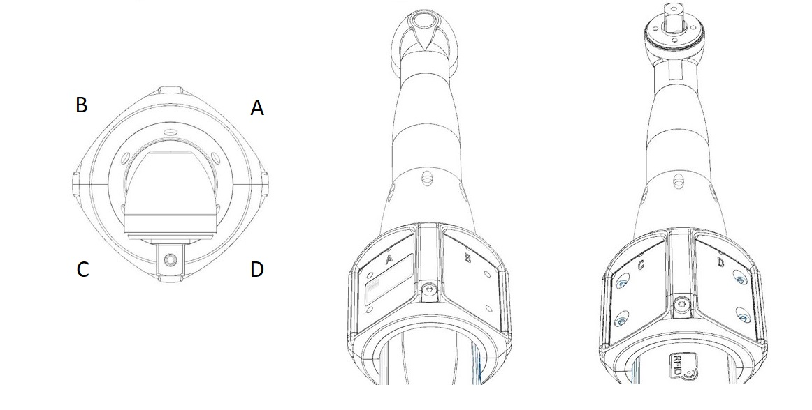
HW-Rev A | A | B | C | D |
|---|---|---|---|---|
X | 0 | 0 | 0 | 0 |
Y | 0 | 0 | 0 | 0 |
Z | -24 | -24 | -24 | -24 |
Rx | 0 | 0 | 0 | 0 |
Ry | 45 | -45 | -135 | 135 |
Rz | 0 | 0 | 0 | 0 |
Angle Tools - Straight Target Position
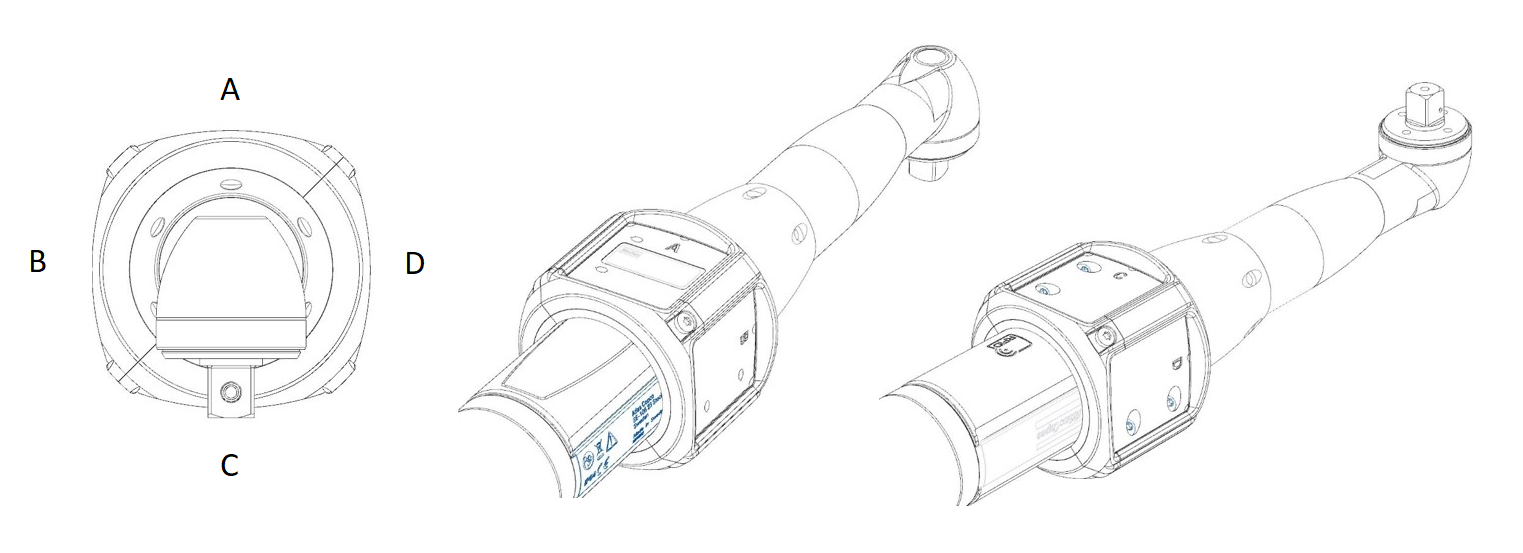
HW-Rev A | A | B | C | D |
|---|---|---|---|---|
X | 0 | 0 | 0 | 0 |
Y | 0 | 0 | 0 | 0 |
Z | -24 | -24 | -24 | -24 |
Rx | 0 | 0 | 0 | 0 |
Ry | 0 | -90 | 180 | 90 |
Rz | 0 | 0 | 0 | 0 |
ICB with Triple Target
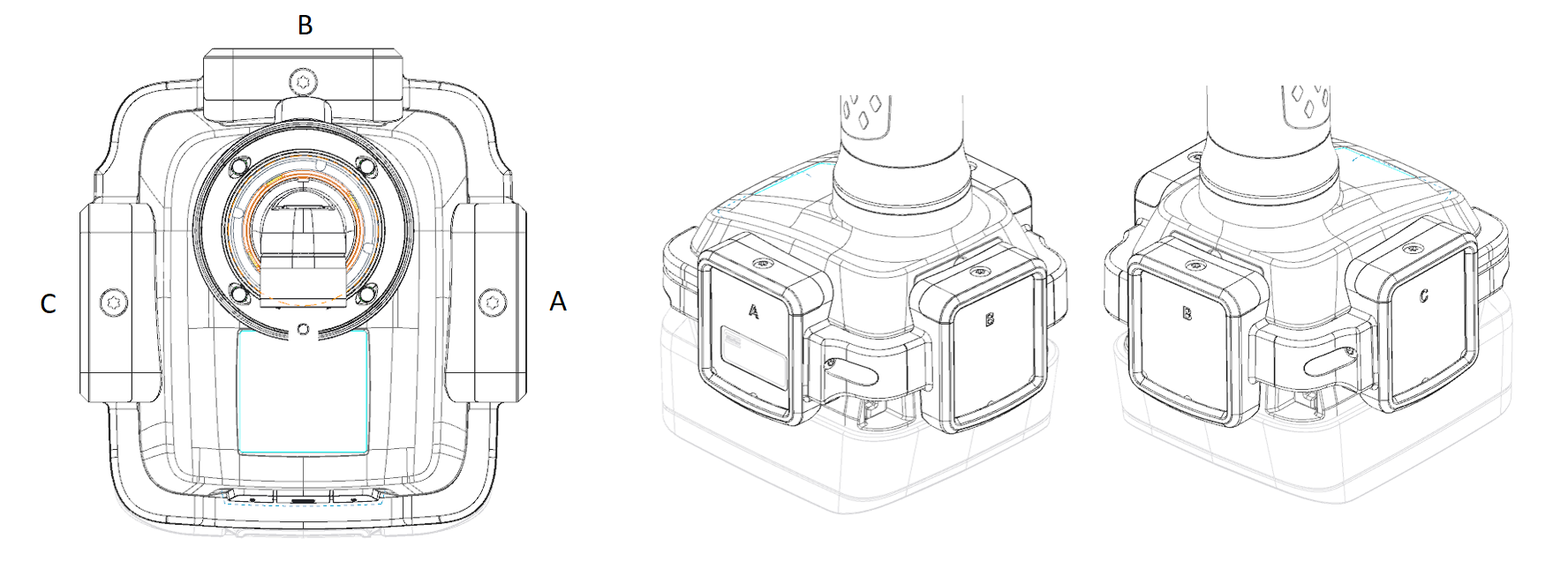
HW-Rev A | A | B | C | Fixed value for Geometry |
|---|---|---|---|---|
X | 0 | 0 | 0 | 0 |
Y | 0 | 0 | 0 | 262 |
Z | -47 | -54 | -47 | 0 |
Rx | 0 | 0 | 0 | 0 |
Ry | 90 | 0 | -90 | 0 |
Rz | 180 | 180 | 180 | 0 |
STwrench with Triple Target

HW-Rev A | A | B | C |
|---|---|---|---|
X | 0 | 0 | 0 |
Y | 0 | 0 | 0 |
Z | -29 | -23 | -29 |
Rx | 0 | 0 | 0 |
Ry | 90 | 0 | -90 |
Rz | 0 | 0 | 0 |
ETP/SRB with Dual Target
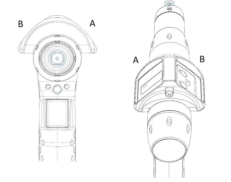
HW-Rev A | A | B |
|---|---|---|
X | -3 | 3 |
Y | 0 | 0 |
Z | -27 | -27 |
Rx | 0 | 0 |
Ry | 45 | -45 |
Rz | 0 | 0 |
HW-Rev B | A | B |
|---|---|---|
X | -6 | 6 |
Y | 0 | 0 |
Z | -29 | -29 |
Rx | 0 | 0 |
Ry | 45 | -45 |
Rz | 0 | 0 |
ETP/SRB with Single Target
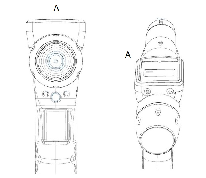
HW-Rev A | A |
|---|---|
X | 0 |
Y | 0 |
Z | -28 |
Rx | 0 |
Ry | 0 |
Rz | 0 |
HW-Rev B | A |
|---|---|
X | 0 |
Y | 0 |
Z | -32 |
Rx | 0 |
Ry | 0 |
Rz | 0 |
TBP with Dual Target
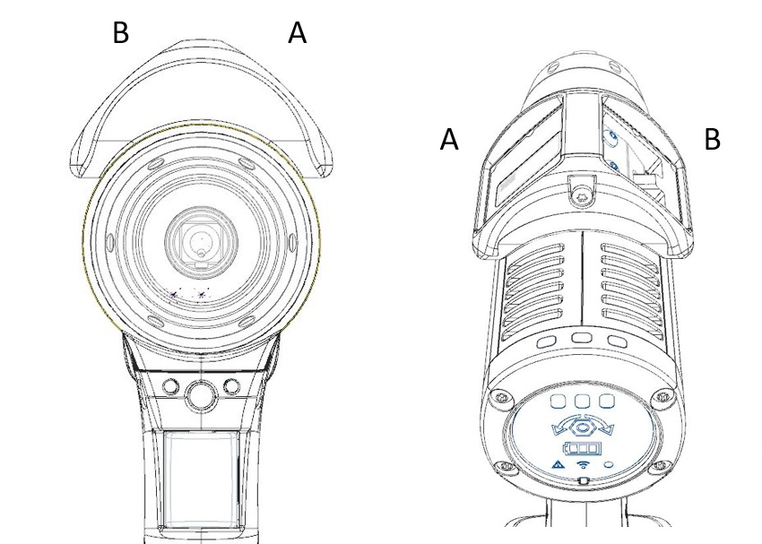
HW-Rev A | A | B |
|---|---|---|
X | -12 | 12 |
Y | 0 | 0 |
Z | -36 | -36 |
Rx | 0 | 0 |
Ry | 45 | -45 |
Rz | 0 | 0 |
HW-Rev B | A | B |
|---|---|---|
X | -13 | 13 |
Y | 0 | 0 |
Z | -37 | -37 |
Rx | 0 | 0 |
Ry | 45 | -45 |
Rz | 0 | 0 |
TBP with Single Target
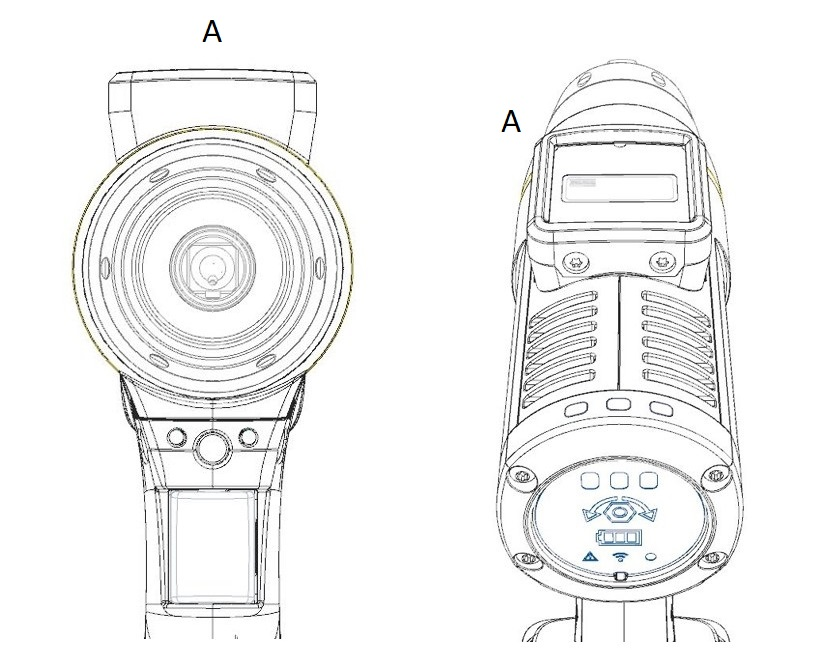
HW-Rev A | A |
|---|---|
X | 0 |
Y | 0 |
Z | -38 |
Rx | 0 |
Ry | 0 |
Rz | 0 |
HW-Rev B | A |
|---|---|
X | 0 |
Y | 0 |
Z | -43 |
Rx | 0 |
Ry | 0 |
Rz | 0 |

