Assembling Instructions
Assembling the GFA Module with Shaft Lid generation 1
For service tool, see Service Equipment for the specific GFA model.
Grease the inside of the idler gears and place over the shafts.
Repeat for all idler gears. The number of idler gears depend on the configuration of the GFA module.
Insert the needle roller bearings. Make sure to insert as many needle roller bearings as there is space for. There should not be any gaps.
Make sure that the parallel pin is inserted.
Apply grease to the idler gears.
Apply grease to the socket gear and place it in the housing. Make sure to place it in the right direction, according to the specification.
Place the upper part of the housing on top of the lower part. Use a press tool and press evenly over the housing.
Make sure that there is no gap between the upper and lower parts of the housing.
Tighten the screws to the specified torque. The number and type of screws depend on the GFA model.
Grease the inside of the input gear and the needle carrier. Place the needle carrier in the input gear.
Use a press tool to push the ball bearing onto the input gear. Use a cylinder with the correct measurements to make the ball bearing go all the way down.
Insert the input gear into the bearing housing.
Place the nut over the bearing housing.
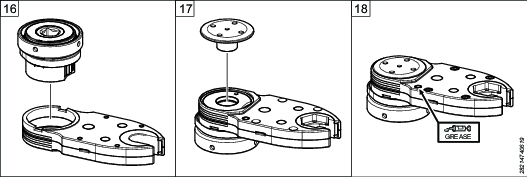
Place the cover plate on the collar back latch. Grease the pawl and spring and insert into the collar back latch.

The collar back latch can include a torque arm flange depending on the configuration.
Push in the pawl and put the collar back latch over the bearing housing. The pawl should go into one of the two grooves of the input gear. Depending on the gear stage and the desired rotational direction, the collar back latch can be placed either with the cover plate facing downwards (A) or upwards (B).
GFA Gear Model
Tightening Rotational
Direction of Output GearMounting Direction of
Collar Back Latch2-stage
Clockwise
Cover plate facing downwards, image A
Counterclockwise
Cover plate facing upwards, image B
3-stage
Clockwise
Cover plate facing upwards, image B
Counterclockwise
Cover plate facing downwards, image A
Turn the input square all the way to locked position. Make sure that the output gear is in open position and insert the input gear into the housing. The teeth of the gears should mesh. Push the input gear all the way down until the input gear is flush with the housing. Make sure that the output gear is in open position when the input gear is in locked position.
Secure the housing in a vice and insert the cover cap into the housing. Push the input gear up from below while tightening the cover cap.
Use a grease gun to fill the housing with grease through the grease nipple. Note that the GFA module can have a different amount of grease nipples depending on the model.
Screw the adapter onto the bearing housing until it stops. Secure the housing in a vice and tighten the nut to specified torque.


Assembling the GFA Module with Shaft Lid generation 2
For service tool, see Service Equipment for the specific GFA model.
Grease the inside of the idler gears and place over the shafts.
Repeat for all idler gears. The number of idler gears depend on the configuration of the GFA module.
Insert the needle roller bearings. Make sure to insert as many needle roller bearings as there is space for. There should not be any gaps.
Make sure that the parallel pin is inserted.
Apply grease to the idler gears.
Apply grease to the socket gear and place it in the housing. Make sure to place it in the right direction, according to the specification.
Place the upper part of the housing on top of the lower part. Use a press tool and press evenly over the housing.
Make sure that there is no gap between the upper and lower parts of the housing.
Tighten the screws securing the lower housing to the specified torque. The number and type of screws depend on the GFA model.
Grease the inside of the input gear and the needle carrier. Place the needle carrier in the input gear.
Use a press tool to push the ball bearing onto the input gear. Use a cylinder with the correct measurements to make the ball bearing go all the way down.
Insert the input gear into the bearing housing.
Place the nut over the bearing housing.
Place the cover plate on the collar back latch. Grease the pawl and spring and insert into the collar back latch.
The collar back latch can include a torque arm flange depending on the configuration.
Push in the pawl and put the collar back latch over the bearing housing. The pawl should go into one of the two grooves of the input gear. Depending on the gear stage and the desired rotational direction, the collar back latch can be placed either with the cover plate facing downwards (A) or upwards (B).
GFA Gear Model
Tightening Rotational
Direction of Output GearMounting Direction of
Collar Back Latch2-stage
Clockwise
Cover plate facing downwards, image A
Counterclockwise
Cover plate facing upwards, image B
3-stage
Clockwise
Cover plate facing upwards, image B
Counterclockwise
Cover plate facing downwards, image A
Turn the input square all the way to locked position. Make sure that the output gear is in open position and insert the input gear into the housing. The teeth of the gears should mesh. Push the input gear all the way down until the input gear is flush with the housing. Make sure that the output gear is in open position when the input gear is in locked position.
Turn the GFA module upside down. Insert the shaft lid into the housing. Check that the keys are in the correct position.
Put the shaft lid plate onto the shaft lid, the shaft lid should fit into the hole in the middle. Make sure the keys fits into the holes in the shaft lid plate. Use a pin spanner to make sure that the shaft lid plate is in the correct position.
Tighten the screws securing the shaft lid plate to the specified torque.
Use a grease gun to fill the housing with grease through the grease nipple. Note that the GFA module can have a different amount of grease nipples depending on the model.
Place the GFA module with the right way up. Screw the adapter onto the bearing housing until it stops. Secure the housing in a vice and tighten the nut to specified torque.


Attaching a Fixed Index Adapter
For service tool, see Service Equipment for the specific GFA model.
Clean the threads of the drive unit and the adapter.
Apply Loctite 2701, or similar, to the threads of the drive unit.
Fasten the drive unit in a vice and tighten the adapter to specified torque, using a C-spanner.
Attach the adapter to the nut.
Tighten the nut to specified torque, using a C-spanner.


Attaching a Fork Adapter
For service tool, see Service Equipment for the specific GFA model.
Remove the bearing shell from the angle head of the tool.
Attach the fork adapter to the angle head.
Fasten the tool to a vice. Clean the threads. Apply Loctite 2701, or similar, to the bearing shell adapter, push it into the fork adapter and tighten to specified torque. Note: this is not the same bearing shell as the one for the angle head, in Step 1.
Clean the threads. Apply Loctite 2701, or similar, to the threads of the adapter. Screw it onto the fork adapter and tighten to specified torque, using a C-spanner.
Attach the nut with the GFA module to the adapter of the drive unit.
Tighten the nut, using a C-spanner.


