Screw Feeding Unit
Product Information
General Information
Safety Signal Words
The safety signal words Danger, Warning, Caution, and Notice have the following meanings:
DANGER | DANGER indicates a hazardous situation which, if not avoided, will result in death or serious injury. |
WARNING | WARNING indicates a hazardous situation which, if not avoided, could result in death or serious injury. |
CAUTION | CAUTION, used with the safety alert symbol, indicates a hazardous situation which, if not avoided, could result in minor or moderate injury. |
NOTICE | NOTICE is used to address practices not related to personal injury. |
Warranty
Product warranty will expire 12 months after the product is first taken into use, but will in any case expire at the latest 13 months after delivery.
Normal wear and tear on parts is not included within the warranty.
Normal wear and tear is that which requires a part change or other adjustment/overhaul during standard tools maintenance typical for that period (expressed in time, operation hours or otherwise).
The product warranty relies on the correct use, maintenance, and repair of the tool and its component parts.
Damage to parts that occurs as a result of inadequate maintenance or performed by parties other than Atlas Copco or their Certified Service Partners during the warranty period is not covered by the warranty.
To avoid damage or destruction of tool parts, service the tool according to the recommended maintenance schedules and follow the correct instructions.
Warranty repairs are only performed in Atlas Copco workshops or by Certified Service Partners.
Atlas Copco offers extended warranty and state of the art preventive maintenance through its ToolCover contracts. For further information contact your local Service representative.
For electrical motors:
Warranty will only apply when the electric motor has not been opened.
Website
Information concerning our Products, Accessories, Spare Parts and Published Matters can be found on the Atlas Copco website.
Please visit: www.atlascopco.com.
ServAid
ServAid is a portal that is continuously updated and contains Technical Information, such as:
Regulatory and Safety Information
Technical Data
Installation, Operation and Service Instructions
Spare Parts Lists
Accessories
Dimensional Drawings
Please visit: https://servaid.atlascopco.com.
For further Technical Information, please contact your local Atlas Copco representative.
Safety Data Sheets MSDS/SDS
The Safety Data Sheets describe the chemical products sold by Atlas Copco.
Please consult the Atlas Copco website for more information www.atlascopco.com/sds.
Packaging
The packaging is intended to protect the individual components from transport damage, corrosion and other damage during transport until assembly. The packaging must not be damaged under any circumstances and should only be removed immediately before assembly.
The Screw Feeding Unit and the boxes are stacked on a pallet and wrapped in a film.
The Screw Feeding Tightening Module is packed in a box with the accessories.
The Power Focus 6000 is packed in a box.
Storage
The devices and, if necessary, spare parts should be stored in a packaged condition, which provides further protection against environmental influences.
The following conditions for storage must be observed
Never store outdoors - not even for a short time
The components should be stored in a dry place, and should be protected from dust and aggressive media
Protect from sunlight
Avoid mechanical vibration
Storage temperature: + 10 ° C to + 55 ° C. High variations of temperature should be avoided
Relative humidity: 5% to 95% (not condensing)
If the device is stored for longer than a month, the condition of all parts and the packaging should be checked regularly, if necessary refresh/renew the preservation
If possible, the packaging should only be removed immediately before assembly
The packaging may contain further information on transport and storage, this information must be strictly observed.
Transporting the Screw Feeding Unit
The Screw Feeding Unit is equipped with recessed grips on the left and right hand sides. For a short transport, these can be used to carry the unit. Optionally, a suspension can be mounted on the mounting plate (green).

All connections should be removed before transport to avoid damage of the connecting cables.
Country of Origin
For the Country of Origin, please refer to the information on the product label.
Dimensional Drawings
Dimensional Drawings can be found either in the Dimensional Drawings Archive, or on ServAid.
Please visit: http://webbox.atlascopco.com/webbox/dimdrw or https://servaid.atlascopco.com.
Overview
Technical Data
Product Data
Maximum Air Pressure | 6.0 bar (87.0 psig) |
Maximum Air Consumption | 400 l/min @ 60 screws per minute (HTM & FTM) 800 l/min @ 60 screws per minute (VTM) |
Fill Volume | 3.15 l |
Screw Size | M3-M6 |
Screw amount approximately | 1500 (M6 x 25) – 18 000 Screws (M3 x 6) |
Weight | 38 kg (84 lb) |
Supply Voltage/Frequency | 230 V/50 Hz (EU Version) or 115V/60Hz (US Version) |
Rated Power | 25 W |
Air Connector | Quick coupling plug KS-4-1/4-A (default) (Changeable to custom specific. Base = G1/4”) |
Main Components of the Screw Feeding System
The individual components of the system can be customer specific, and may therefore differ from the components shown here.
The screw fastening system consists of the following main components

No. | Component | Function |
1 | Screw Feeding Tightening Module
| To carry out the screwing process. |
2 | Power Focus 6000 | Control and monitoring of the screw fastening and feeding process. |
3 | Screw Feeding Unit | Transport, sort and separating the screws, feed the screws into the Screw Feeding Tightening Module using compressed air. |
4 | Tool Cable | Electrical connection between the Power Focus 6000 and the Screw Feeding Tightening Module. |
5 | Connecting Line | Electrical connection between the trigger on the Screw Feeding Tightening Module and the Screw Feeding Unit. |
6 | Air Connection | Pneumatic connection for Forward and Return Stroke between the Screw Feeding Tightening Module and the Screw Feeding Unit. |
7 | Connection Cable | Electrical connection between the Power Focus 6000 and the Screw Feeding Unit. |
8 | Signal Line | Connection between the Power Focus 6000 and the Screw Feeding Unit. |
9 | Feeding Tube | Pneumatic transport of screws from the Screw Feeding Unit to the Screw Feeding Tightening Module. |
For more information about the Screw Feeding Tightening Module, see product information for the Screw Feeding Tightening Module.
For more information about the Power Focus 6000, see product information for the Power Focus 6000.
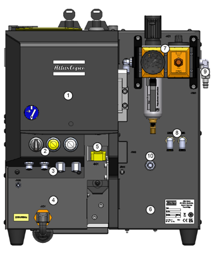
Components and Function of the Screw Feeding Unit
Construction
Housing with Screw Container, Step Conveyor Unit, Linear Guide, and Separating Unit
Housing with power supply
Housing with electrical and pneumatic components
Sensors for monitoring
Main components
Handheld Tightening Module Screw Feeding Unit
Fixtured Tightening Module Screw Feeding Unit
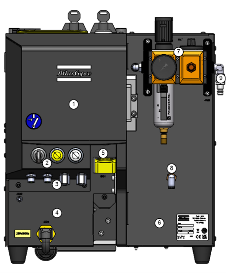
No. | Description | Function |
1 | Housing |
|
2 | Controls | Rotary Switch: Automatic or Bit Change mode. Illuminated Push Button: Error display, acknowledge errors. Status light. |
3 | Connections | Connection to the Power Focus 6000, start signal for the Screw Feeding Tightening Module, and other connections. |
4 | Housing for power supply | Control voltage and IEC Connector for mains connection. |
5 | Ring Sensor | Bushing for the Feeding Tube, the sensor detects outgoing screws to the Screw Feeding Tightening Module. |
6 | Housing | Electrical and pneumatic components. |
7 | Maintenance Unit | Pressure reducer with Shut-Off valve and filter. |
8 | Air Connections | Pneumatic Forward and Return Stroke connection between the Screw Feeding Tightening Module and the Screw Feeding Unit, or the supply to the Valve Control Unit (VCU). |
9 | Air supply | Connection to the compressed air supply. |
10 | Trigger Input Connector | Connection to the tool trigger input. |
The feeding process
The screws are filled into the Screw Container via the Filling Hatch.
From the Screw Container, the screws reach the Step Conveyor Unit and are transported upwards via movable steps.
The screws fall into the V-block of the Linear Guide (hanging from the collar), where they are guided into the Separating Unit.
The separation process
When a screw is required in the Screw Feeding Tightening Module, a single screw is separated out from the fasteners aligned on the Linear Guide.
The separated screw is blown into the Screw Feeding Tightening Module.
Screw Container

No. | Description | Function |
1 | Screw Container | Container for screws with lockable Filler Hatch. |
2 | Level Sensor | Level Sensor for the Screw Container. |
3 | Adjustment for screw passage | The number of screws that can pass through can be adjusted using the Height-adjustable Plate. |
Step Conveyor Unit and Linear Guide

No. | Description | Function |
1 | Step Conveyor Unit | Pneumatic transport of the screws via movable steps. |
2 | V-block of the Linear Guide | Pick up the screws from the top step of the Step Conveyor Unit and further transport them to the Linear Guide. |
3 | Linear Guide | Conveys the screws hanging by the collar and leads them to the Separating Unit. |
4 | Air Sorting | Adjustable air supply and position of the nozzles for sorting out screws that are incorrectly positioned. |
5 | Rail Fill Sensor | Detects the fill level of the Linear Guide. If it is full, no new screws are lifted from the Step Conveyor Unit onto the Linear Guide. |
Separating Unit

No. | Description | Function |
1 | Separating Unit | Separation of a single screw |
2 | Separating Slide | Disconnects a single screw |
3 | Cylinder | Moves the Separating Slide to separate a screw |
4 | Sensor | Inductive detection of the position of the Separating Slide |
5 | Ring Sensor | Detection of the screw in the Feeding Tube |
Overview of Electrical and Pneumatic Components

No. | Description | Function |
1 | Valve Terminal | Connection of all Pneumatic Components |
2 | OR- + Pressure Valve | Switchover for Intermediate Screwdriver Position |
3 | I / O hub | Sensor / Switch Port Module |
4 | Multiprotocol I / O module | Control Unit for the Screw Feeding Unit |
Feeding Tube
The Feeding Tube transports the screws from the Screw Feeding Unit to the Swivel Arm of the Screw Feeding Tightening Module by air pressure.

No. | Description | Function |
1 | Ring Sensor | Detects when the fastener leaves the seperation unit. |
2 | Feeding Tube | Feeds the screws from the Screw Feeding Unit to the Screw Feeding Tightening Module |
3 | Screw Feeding Tightening Module | Shows the setup with a Handheld Tightening Module. For further information about the other tightening modules, refer to the corresponding product information. |
Controls

No. | Description | Function |
1 | Rotary Switch | Bit Change position: The Bit Complete on the Screw Feeding Tightening Module moves forwards, and the screw is ejected. Automatic position: The Bit Complete on the Screw Feeding Tightening Module moves backward, and a screw is loaded. Disabled for fixture feeders for uninterrupted automatic mode. Function can be enabled in feeders web HMI. |
2 | Illuminated Push Button | Lit up in yellow in the event of an error. Errors can be acknowledged. |
3 | Status Light | Lit up in white when ready. Unlit when switched off. |
4 | Regulator | The compressed air supply. |
5 | Shut-off Valve | Switch ON/OFF the compressed air supply and vent. |
Functional Description of the Screw Feeding Unit
The Screw Feeding Unit stocks, transports, sorts, and separates the screws and transports them via the Feeding Tube to the Screw Feeding Tightening Module.
There is a supply of screws in the Screw Container of the Screw Feeding Unit. The fill level is monitored by a Sensor at the bottom of the Screw Container. Optionally, an Ultrasonic Sensor can be used to monitor the level.
The screws reach the Step Conveyor Unit from the Screw Container. The screws are moved upwards via movable steps.
From the top stage of the Step Conveyor unit, the screws fall onto the V-block.
The screws then drop into the Linear Guide hanging from the collar. There the screws are fed to the Separating Unit. The Air Sorting causes unordered screws to fall back into the Screw Container. The Rail Fill Sensor checks the fill level of the Linear Guide. If the Linear Guide is full, no new screws are supplied to the Step Conveyor.
If a screw is required in the Feeding Head of the Screw Feeding Tightening Module, a single screw is provided by the Separating Slide.
Then the screw is blown into the Screw Feeding Tightening Module through the Feeding Tube.
Technical Product Data
Technical Product Data can be found on either ServAid, or the Atlas Copco website.
Please visit: https://servaid.atlascopco.com or www.atlascopco.com.
Intended use of the Screw Feeding Unit
The Screw Feeding Unit is used exclusively for storing, sorting, separating, and blowing screws. The Screw Feeding Unit is controlled by the Power Focus 6000.
The Screw Feeding Unit
May only be used inside closed rooms.
May only be operated with the system components described here.
Must not be used outdoors or in damp rooms.
With its system components must not be used in an explosive environment.
May only be used with screws sized M3-M6.
Permitted use for the individual components of the incomplete machine
Screw Feeding Unit
Use for feeding screws to the Screw Feeding Tightening Module.
Feeding Tube
Use for transporting the screws from the Screw Feeding Unit to the Screw Feeding Tightening Module.
Screw Feeding Tightening Module
Assembly of screw connections that require a defined torque or a defined angle of rotation.
Valve Control Unit
There are multiple types of Valve Control units which are linked to the corresponding tightening module. These are used only for fixtured installations (automatic) and not for handheld applications (semi-automatic).
Cable (electrical)
Use for electrical supply and control of the tightening system.
Hoses (pneumatic)
Use for supplying the tightening system with pneumatic energy.
Power Focus 6000
Use for power supply as well as control and monitoring of the tightening system.
Service Overview
Service Recommendations
Preventive maintenance is recommended at regular intervals. See the detailed information on preventive maintenance. If the product is not working properly, take it out of service and inspect it.
If no detailed information about preventive maintenance is included, follow these general guidelines:
Clean appropriate parts accurately
Replace any defective or worn parts
Installation
Installation Requirements
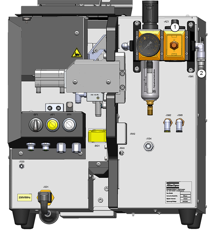
Connecting the Screw Feeding Unit to the Compressed Air Supply
The compressed air must be free of any kind of contamination.
Use the Shut-off Valve (1) to switch off the compressed air supply. This will vent and secure against unwanted movement.
Connect the Tube for the compressed air supply to the Air Supply on the Screw Feeding Unit (2).
If all components of the Screw Feeding system are pneumatically connected, the compressed air supply can be reactivated by turning on the Shut-off Valve .
Installation Instructions
Assembly and Connection of the Screw Feeding Unit
Position the Screw Feeding Unit so that the Controls can be reached and the cable and hose routing has no sharp bends.
The Screw Feeding Unit must be level and aligned.
Connecting the Screw Feeding Unit to the Feeding Tube
Open the Cover Lid.
Push the Feeding Tube into the Feeding Tube Connection. Push the Feeding Tube Connection through the Ring Sensor and into the connection on the Screw Feeding Unit (1)
Secure the Feeding Tube Connection by tightening the Clamping screw on the connection on the Screw Feeding Unit.
Attach the other end of the Feeding Tube to the Swivel Arm of the Screw Feeding Tightening Module (see product information for the Screw Feeding Tightening Module).
Connecting the Screw Feeding Unit to the Pneumatic Forward and Return Stroke (Handheld only)
Push the Hose for Forward Stroke (black) onto the connection with the black ring (2).
Push the Hose for Return Stroke (yellow) onto the connection with the yellow ring (3).
Connect the other ends of the Forward and Return Stroke Hoses to the corresponding connections on the Screw Feeding Tightening Module (see product information for the Screw Feeding Tightening Module).
Connecting the Screw Feeding Unit to the Start Button on the Screw Feeding Tightening Module (Handheld only)
Connect the Connection Line to terminal (B25, 4).
Connect the other end of the Connection Line to the corresponding connection on the Screw Feeding Tightening Module (see product information for the Screw Feeding Tightening Module).
Connecting the Screw Feeding Unit to the Valve Control Unit (Fixtured only)
For the correct wiring diagram, please refer to the product information of the Fixtured Tightening Module.
Connecting the Screw Feeding Unit to the Power Focus 6000
Connect the Connection Cable for control voltage coming from the Power Focus 6000 to connection (B26).
Connect the Signal Line coming from the Power Focus 6000 to connection (B22) or (B23)(Handheld only).
Connecting the Screw Feeding Unit to the Network
Insert the mains plug into the socket.

Air Sorting
Air Sorting is used to remove screws that are not in the correct position from the Linear Guide. The direction of the Air Sorting can be adjusted via 3 nozzles.
The nozzle position is factory set and lacquered. If adjustment is necessary, this should only be carried out by Atlas Copco service technicians.
If the paint on the adjusting screws is damaged, the guarantee can be void.
Adjusting the Screw Passage in the Screw Container
The height of the Plate in the Screw Container is factory set and depending on the screw geometry. If too many screws slip through or if they jam, the setting can be changed.
Open the Cover Lid.
The plate height is adjusted with two screws (blue arrows) - loosen the screws and push the Plate upwards or downwards, then fasten the screws again.

Rail Fill Sensor
The Rail Fill Sensor is factory set depending on the screw head geometry and the distance between the Cover and Guide Rails. If adjustment is necessary, this should only be carried out by Atlas Copco service technicians.
Separating Unit
The height must be set according to the screw geometry (factory setting) so that the screw can be cut off cleanly from the Guide Rail at the transition. If adjustment is necessary, this should only be carried out by Atlas Copco service technicians.
Software Instructions
Fieldbus Bitmapping Standalone Feeder (Fixtured)
LinePLC -> Feeder
Note that some PLCs or communication Gateways swap the Bytes within a Word.
Byte | Bit | Name | Function |
0 | 0 | Livebit | Feeder will mirror it back, only for testing communication. |
0 | 1 | Movement release | Allow movements in the feeder and fixture. |
0 | 2 | Reset error | Resets error |
0 | 3 | ||
0 | 4 | ||
0 | 5 | ||
0 | 6 | Separate screw | Starts separating the screw. The screw will be in the feeding tube until the blow air is activated. Don’t separate more than one screw in the tube. |
0 | 7 | ||
1 | 0 | ||
1 | 1 | Blow screw | Activates feeding air while TRUE transports a previously separated screw. |
1 | 2 | ||
1 | 3 | ||
1 | 4 | ||
1 | 5 | ||
1 | 6 | ||
1 | 7 |
Feeder -> Line PLC
Note that some PLCs or communication Gateways swap the Bytes within a Word.
Byte | Bit | Name | Function |
0 | 0 | Livebit | Mirror back livebit input, only for testing communication. |
0 | 1 | Ready for command | TRUE if the tool is without errors and the switch for maintenance mode is inactive and the movement release is active. |
0 | 2 | Error | TRUE while any error is active until error is reset through Fieldbus or with the button. |
0 | 3 | ||
0 | 4 | ||
0 | 5 | ||
0 | 6 | Separate active | Starts separating the screw. The screw will be in the feeding tube until the blow air is activated. Don’t separate more than one screw in the tube. |
0 | 7 | Separate done | Screw successfully separated into the tube. |
1 | 0 | ||
1 | 1 | Blow air active | The blow air is activated by the Line-PLC through Fieldbus. |
1 | 2 | Refill screws | The screw feeder is running low on screws. |
1 | 3 | ||
1 | 4 | Reset button | TRUE while reset button on the feeder is pressed. |
1 | 5 | Maintenance switch | TRUE while the maintenance switch is active. |
1 | 6 | ||
1 | 7 | ||
2 | 0 | ErrorNumber (INT) | Refer to Error List |
2 | 1 | ErrorNumber (INT) | Refer to Error List |
2 | 2 | ErrorNumber (INT) | Refer to Error List |
2 | 3 | ErrorNumber (INT) | Refer to Error List |
2 | 4 | ErrorNumber (INT) | Refer to Error List |
2 | 5 | ErrorNumber (INT) | Refer to Error List |
2 | 6 | ErrorNumber (INT) | Refer to Error List |
2 | 7 | ErrorNumber (INT) | Refer to Error List |
3 | 0 | ErrorNumber (INT) | Refer to Error List |
3 | 1 | ErrorNumber (INT) | Refer to Error List |
3 | 2 | ErrorNumber (INT) | Refer to Error List |
3 | 3 | ErrorNumber (INT) | Refer to Error List |
3 | 4 | ErrorNumber (INT) | Refer to Error List |
3 | 5 | ErrorNumber (INT) | Refer to Error List |
3 | 6 | ErrorNumber (INT) | Refer to Error List |
3 | 7 | ErrorNumber (INT) | Refer to Error List |
Bitmapping FTM Bitstroke & Headstroke
LinePLC -> Feeder
Note that some PLCs or communication Gateways swap the Bytes within a Word.
Byte | Bit | Name | Function |
0 | 0 | Livebit | Mirror back livebit input, only for testing communication. |
0 | 1 | Movement release | TRUE if the tool is without errors and the switch for maintenance mode is inactive and the movement release is active. |
0 | 2 | Reset error | TRUE while any error is active until the error is reset through Fieldbus or with the button. |
0 | 3 | Extend Bitstroke | The Bit will extend while TRUE. |
0 | 4 | Extend Headstroke | Headstroke will extend while TRUE (optional). |
0 | 5 | ||
0 | 6 | Feed screw | Starts the feeding process and can be activated even while the screw is already in jaws. The screw will be separated and fed to the head when jaws is empty. |
0 | 7 | Screw removed | Removes the screw from the head, enabling the feeding of a new screw. |
1 | 0 | ||
1 | 1 | Purge System | Activates feeding air while TRUE. It can be required in some faulty situations, to regain a defined state. Not required for normal feeding process. |
1 | 2 | ||
1 | 3 | ||
1 | 4 | ||
1 | 5 | ||
1 | 6 | ||
1 | 7 |
Feeder -> Line PLC
Note that some PLCs or communication Gateways swap the Bytes within a Word.
Byte | Bit | Name | Function |
0 | 0 | Livebit | Mirror back livebit input, only for testing communication. |
0 | 1 | Ready for command | TRUE if the tool is without errors and the switch for maintenance mode is inactive and the movement release is active. |
0 | 2 | Error | TRUE while any error is active until the error is reset through Fieldbus or with the button. |
0 | 3 | Bit in homeposition | |
0 | 4 | Headstroke in homeposition | |
0 | 5 | Headstroke in working position | |
0 | 6 | Feeding active | The feeding process is started, the screw will be fed to the tool once Bit is in the home position. |
0 | 7 | Screw in head | Screw successfully teleported into jaws. Bitstroke can now extend, and the tightening process can start. The signal is set to FALSE when Bit leaves the home position. The actual removal of the screw cannot be guaranteed. |
1 | 0 | Purge required | Screw-state unknown, purge required to regain defined state. |
1 | 1 | Purge active | The Purge is activated by the Line-PLC through Fieldbus. |
1 | 2 | Refill screws | The screw feeder is running low on screws. |
1 | 3 | MoveOK | The tool is in the home position (Bit and Headstroke retracted) and no movement is to be expected. It can be used as a movement release e.g. for a robot. |
1 | 4 | Reset button | TRUE while the reset button on the feeder is pressed. |
1 | 5 | Maintenance switch | TRUE while the Maintenance switch is active. |
1 | 6 | ||
1 | 7 | ||
2 | 0 | ErrorNumber (INT) | Refer to Error List |
2 | 1 | ErrorNumber (INT) | Refer to Error List |
2 | 2 | ErrorNumber (INT) | Refer to Error List |
2 | 3 | ErrorNumber (INT) | Refer to Error List |
2 | 4 | ErrorNumber (INT) | Refer to Error List |
2 | 5 | ErrorNumber (INT) | Refer to Error List |
2 | 6 | ErrorNumber (INT) | Refer to Error List |
2 | 7 | ErrorNumber (INT) | Refer to Error List |
3 | 0 | ErrorNumber (INT) | Refer to Error List |
3 | 1 | ErrorNumber (INT) | Refer to Error List |
3 | 2 | ErrorNumber (INT) | Refer to Error List |
3 | 3 | ErrorNumber (INT) | Refer to Error List |
3 | 4 | ErrorNumber (INT) | Refer to Error List |
3 | 5 | ErrorNumber (INT) | Refer to Error List |
3 | 6 | ErrorNumber (INT) | Refer to Error List |
3 | 7 | ErrorNumber (INT) | Refer to Error List |
Bitmapping VTM
LinePLC -> Feeder
Note that some PLCs or communication Gateways swap the Bytes within a Word.
Byte | Bit | Name | Function |
0 | 0 | Livebit | Mirror back livebit input, only for testing communication. |
0 | 1 | Movement release | Allow movements in the Feeder and fixture. |
0 | 2 | Reset error | Resets error. |
0 | 3 | Extend Bitstroke | The Bit will extend while TRUE. |
0 | 4 | Extend Headstroke | Headstroke will extend while TRUE (optional). |
0 | 5 | ||
0 | 6 | Pick up screw | Starts the picking process. The screw will be picked from the slider. When the screw is picked successfully, the screw feeder will automatically feed a new screw to the slider. |
0 | 7 | Screw removed | The screw removed from the head disables the vacuum and enables the next picking. |
1 | 0 | ||
1 | 1 | Purge System | Activates a purge cycle, where the system will try to eject screws, that are already in the system, to reach a defined state. |
1 | 2 | ||
1 | 3 | ||
1 | 4 | ||
1 | 5 | ||
1 | 6 | ||
1 | 7 |
Feeder -> Line PLC
Note that some PLCs or communication Gateways swap the Bytes within a Word.
Byte | Bit | Name | Function |
0 | 0 | Livebit | Mirror back livebit input, only for testing communication. |
0 | 1 | Ready for command | TRUE if the tool is without errors and the switch for maintenance mode is inactive and the movement release is active. |
0 | 2 | Error | TRUE while any error is active until the error is reset through Fieldbus or with the button. |
0 | 3 | Bit in homeposition | |
0 | 4 | ||
0 | 5 | ||
0 | 6 | Picking active | The picking process is started, and the tool head will pick a screw from the slider. |
0 | 7 | Screw in head | The screw is on the tool, vacuum is active. |
1 | 0 | Purge required | Screw-state unknown, purge required to regain defined state. |
1 | 1 | Purge active | The purge cycle is activated by the Line-PLC through Fieldbus. |
1 | 2 | Refill screws | The screw feeder is running low on screws. |
1 | 3 | MoveOK | The tool is in the home position (Bit and Headstroke retracted) and no movement is to be expected. It can be used as a movement release e.g. for a robot. |
1 | 4 | Reset button | TRUE while the reset button on the feeder is pressed. |
1 | 5 | Maintenance switch | TRUE while the Maintenance switch is active. |
1 | 6 | RotateBit | Request to rotate the tool during picking, to help find the screw. Especially important with sockets. |
1 | 7 | ||
2 | 0 | ErrorNumber (INT) | Refer to Error List |
2 | 1 | ErrorNumber (INT) | Refer to Error List |
2 | 2 | ErrorNumber (INT) | Refer to Error List |
2 | 3 | ErrorNumber (INT) | Refer to Error List |
2 | 4 | ErrorNumber (INT) | Refer to Error List |
2 | 5 | ErrorNumber (INT) | Refer to Error List |
2 | 6 | ErrorNumber (INT) | Refer to Error List |
2 | 7 | ErrorNumber (INT) | Refer to Error List |
3 | 0 | ErrorNumber (INT) | Refer to Error List |
3 | 1 | ErrorNumber (INT) | Refer to Error List |
3 | 2 | ErrorNumber (INT) | Refer to Error List |
3 | 3 | ErrorNumber (INT) | Refer to Error List |
3 | 4 | ErrorNumber (INT) | Refer to Error List |
3 | 5 | ErrorNumber (INT) | Refer to Error List |
3 | 6 | ErrorNumber (INT) | Refer to Error List |
3 | 7 | ErrorNumber (INT) | Refer to Error List |
Runtime Diagrams
Fixtured Tightening Module
Startup
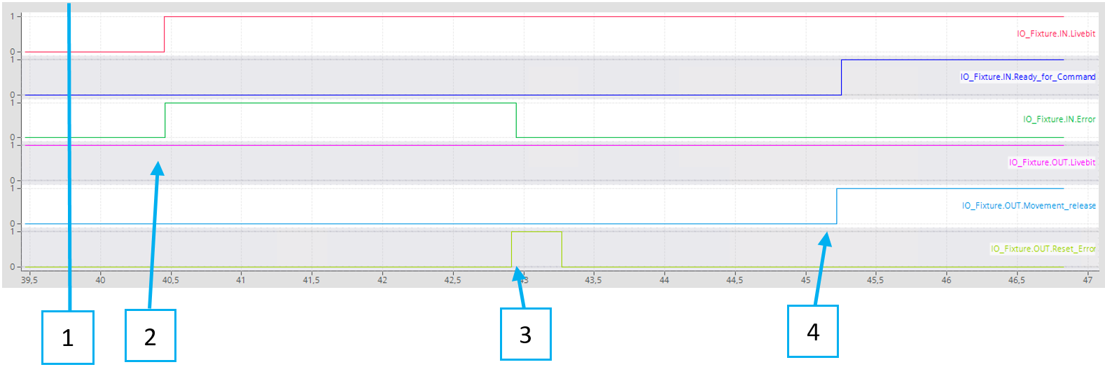
After powering on the feeder, it will need about 5 sec until it is ready for operation. Livebit is set to TRUE from the PLC.
Livebit is responsive. Error is true. Screw in head is true.
Reset error. Error from the feeder is low.
Movement release is TRUE. Feeder is ready for command.
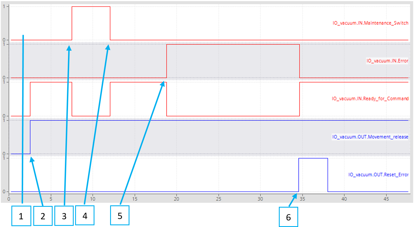
Movement release
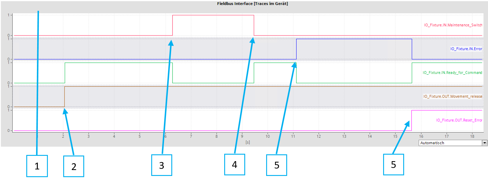
No error is present. The maintenance switch is OFF. The movement release is OFF.
Movement release is set to TRUE. Ready for command turns TRUE.
Maintenance Switch is activated. Ready for command turns FALSE.
Maintenance switch is deactivated. Ready for command turns TRUE.
Error occurs. Error-bit turns TRUE. Ready for command turns FALSE.
Error is resolved and reset Error turns FALSE. Ready for command turns TRUE.
Feeding a screw and tightening process
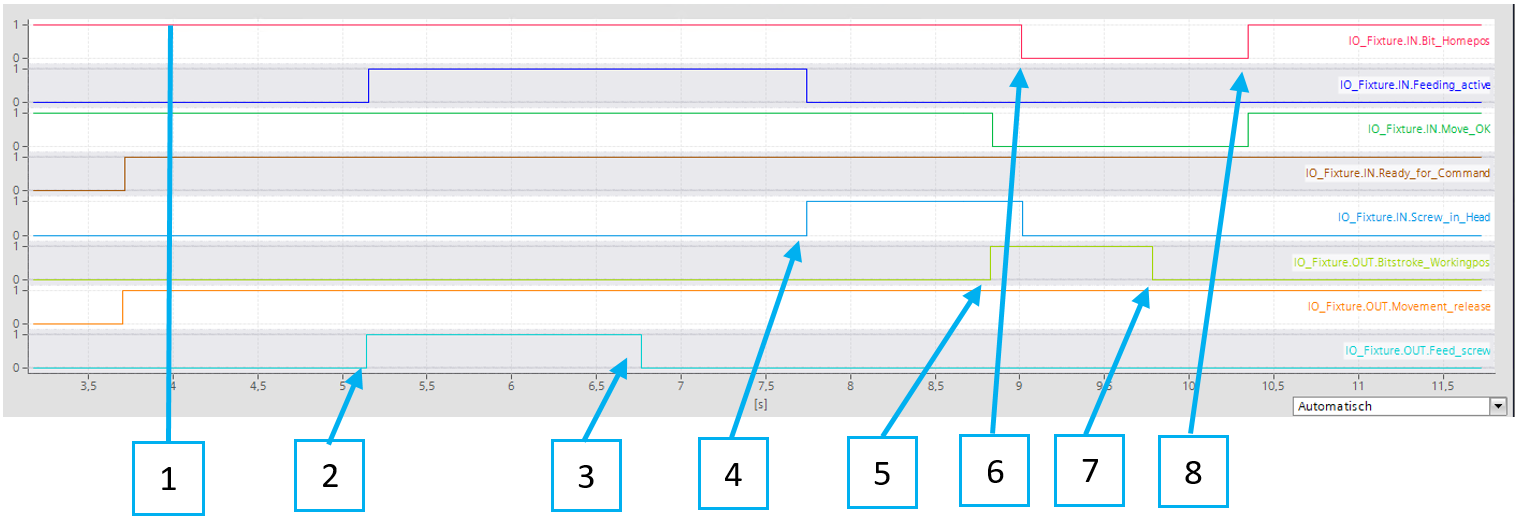
Feeder is ready for command.
Signal Feed screw is set to TRUE. Signal Feeding active returns with TRUE.
Once Feeding active is TRUE, Feed Screw can be reset to FALSE. The feeding process will keep activated until the screw is in the head, or an error occurs.
The screw arrived in the head, Feeding process is finished.
Now the Bitstroke is extended to the working position with the signal Bitstroke Workingpos. Because the Bitstroke is in movement, Move OK goes FALSE.
Bitstroke left the home position. The screw in the Head goes to FALSE. Once the Screw in the Head is FALSE, the feeding process can be triggered again, to prepare the next screw.
Bitstroke Workingpos is reset, and the bit will retract to the home position.
Bitstroke arrived in the home position. Move OK returns to TRUE, it is now safe to move the fixture.
Feeding error
The error can be acknowledged with the yellow button or with the Reset Error Bit in the Fieldbus interface. However, there are errors that might lead to congestion in the feeding tube if they are reset. For that reason, there is the bit Purge Required. This bit is true when the feeder control cannot be certain of the state of the screw. After the System was purged, the error can be reset.
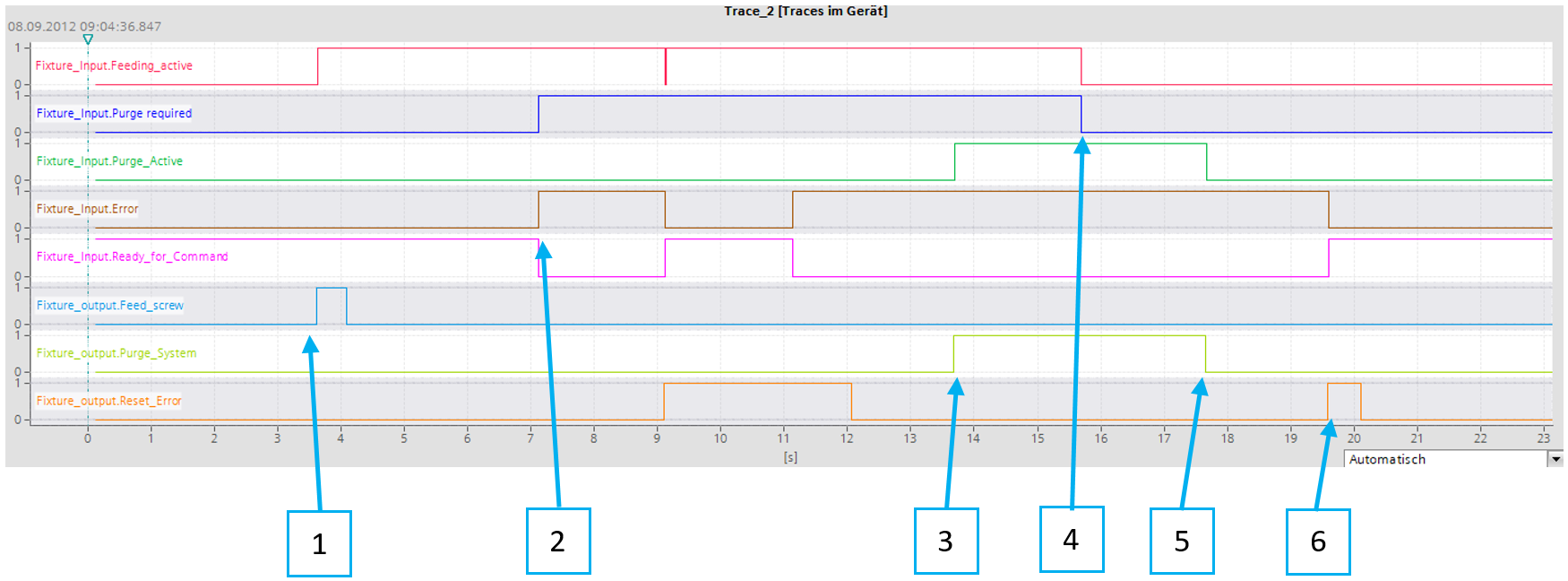
The feeding process has started.
The error occurs, and a purge is required.
Purge is activated by the Line-PLC.
After enough time has passed, the purge required is reset to FALSE.
Purging is deactivated.
The error is reset, and the feeder is ready again.
Make sure that after a fault has occurred, the system is inspected for excess screws in the jaws, swivel arm, or in/after the separation, to avoid congestion that may lead to damage to the system.
Vacuum Tightening Module
Startup
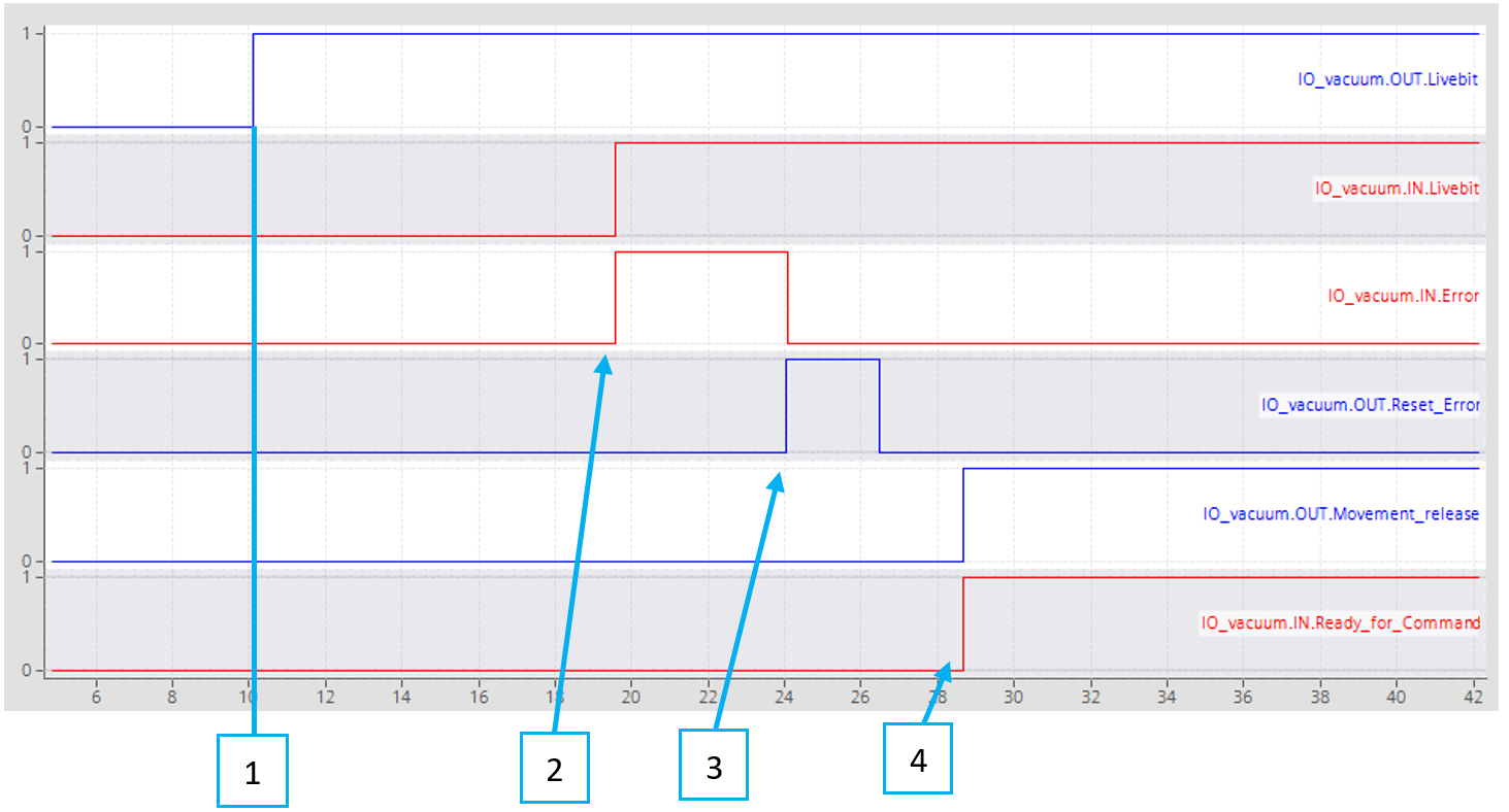
After powering on the feeder, it will need about 5 sec until it is ready for operation. Livebit is set to TRUE from the PLC.
Livebit is responsive. Error is true. Screw in head is true.
Reset error. Error from the feeder is low.
Movement release is TRUE. Feeder is ready for command.
Movement release
No error is present. The maintenance switch is OFF. The movement release is OFF.
Movement release is set to TRUE. Ready for command turns TRUE.
Maintenance Switch is activated. Ready for command turns FALSE.
Maintenance switch is deactivated. Ready for command turns TRUE.
Error occurs. Error-bit turns TRUE. Ready for command turns FALSE.
Error is resolved and reset Error turns FALSE. Ready for command turns TRUE.
Picking a screw and tightening process
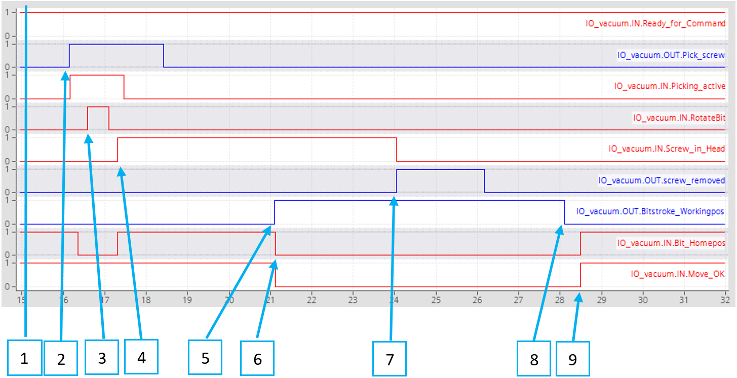
The feeding to the slider module happens automatically and does not need to be triggered. The command feed screw initiates the picking of the screw that is already in the slider.
Feeder is ready for command.
The signal pick screw is set to TRUE. It reacts only to the rising edge and can be reset right after signal picking active returns with TRUE. The picking process will keep activated until the screw is in the head, or an error occurs.
While moving the bit or socket towards the picking position, the feeder will request RotateBit, to help engage with the screw. Especially with sockets rotating during picking is essential. Activating bit rotation must be done by PLC.
The screw is on the head, the vacuum level is reached, and the picking process is finished. A new screw will be pre-loaded to the slider automatically and does not require further action.
Now the Bitstroke is extended to the working position with the signal Bitstroke Workingpos. Because the Bitstroke is in movement, Move OK goes FALSE.
Bitstroke left the home position. Now the tightening process can be started.
The screw in the head is reset when the signal screw removed is TRUE. At this point, the vacuum generator also turns OFF.
Bitstroke Workingpos is reset, and the bit will retract to the home position.
Bitstroke arrived in the home position. Move OK returns to TRUE, it is now safe to move the fixture.
Feeding error
The error can be Acknowledged with the Yellow button or with the Reset Error Bit in the Fieldbus interface. However, there are errors that might lead to congestion in the feeding tube if they are reset. For that reason, there is the bit Purge Required. This bit is true when the feeder control cannot be certain of the state of the screw. After the System was purged, the error can be reset.
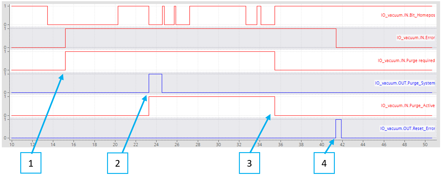
In this example, the ring sensor was disconnected, so no screw arrival was detected at the tool, after blowing the screw to the tool.
The error occurs, and a purge is required.
Purge is activated by the Line-PLC.
After the purge-cycle, purge required is reset to FALSE.
The error is reset, and the feeder is ready again.
Make sure that after a fault has occurred, the system is inspected for excess screws in the sliding mechanic or in/after the separation, to avoid congestion that may lead to damage to the system.
Error Codes
The below error codes are the same for the Handheld Tightening Module, Fixtured Tightening Module, and Vacuum Tightening Module.
No. | State | Unit | Error Message |
0 | General | No Fault | |
1 | System | Overcurrent_Isys | |
2 | System | Overvoltage_Field_Supply_V2 | |
3 | System | Undervoltage_Field_Supply_V2 | |
4 | System | Overvoltage_Field_Supply_V1 | |
5 | System | Undervoltage_Field_Supply_V1 | |
6 | System | Modulebus_Communication_Lost | |
7 | Modulebus_Configuration_Error | ||
8 | System | IO_Basic_Diagnostics_Overcurrent_output_1 (Internal IO-Hub) | |
9 | System | IO_Basic_Diagnostics_Overcurrent_output_3 (Valveblock) | |
10 | System | IO_Basic_Diagnostics_Overcurrent_output_5 (NA) | |
11 | System | IO_Basic_Diagnostics_Overcurrent_output_7 (IO-Hub fixture) | |
12 | System | IO_Diagnostics_Input_Wrong_or_missing_device_0 (Internal IO-Hub) | |
13 | System | IO_Diagnostics_Input_Wrong_or_missing_device_2 (Valveblock) | |
14 | System | IO_Diagnostics_Input_Wrong_or_missing_device_4 (NA) | |
15 | System | IO_Diagnostics_Input_Wrong_or_missing_device_6 (IO-Hub fixture) | |
16 | System | IO_Diagnostics_Input_Common_error_0 (Internal IO-Hub) | |
17 | System | IO_Diagnostics_Input_Common_error_2 (Valveblock) | |
18 | System | IO_Diagnostics_Input_Common_error_4 (NA) | |
19 | System | IO_Diagnostics_Input_Common_error_6 (IO-Hub fixture) | |
31 | System | Overcurrent_Isys | |
32 | System | Overvoltage_Field_Supply_V2 | |
33 | System | Undervoltage_Field_Supply_V2 | |
34 | System | Overvoltage_Field_Supply_V1 | |
35 | System | Undervoltage_Field_Supply_V1 | |
36 | System | Modulebus_Communication_Lost | |
37 | System | Modulebus_Configuration_Error | |
38 | System | IO_Basic_Diagnostics_Overcurrent_output_1 | |
39 | System | IO_Basic_Diagnostics_Overcurrent_output_3 | |
40 | System | IO_Basic_Diagnostics_Overcurrent_output_5 (vac sens) | |
41 | System | IO_Basic_Diagnostics_Overcurrent_output_7 (IO-Hub fixture) | |
42 | System | IO_Diagnostics_Input_Wrong_or_missing_device_0 | |
43 | System | IO_Diagnostics_Input_Wrong_or_missing_device_2 | |
44 | System | IO_Diagnostics_Input_Wrong_or_missing_device_4 (vac sens) | |
45 | System | IO_Diagnostics_Input_Wrong_or_missing_device_6 (IO-Hub fixture) | |
46 | System | IO_Diagnostics_Input_Common_error_0 | |
47 | System | IO_Diagnostics_Input_Common_error_2 | |
48 | System | IO_Diagnostics_Input_Common_error_4 (vac sens) | |
49 | System | IO_Diagnostics_Input_Common_error_6 (IO-Hub fixture) | |
100 | Startup | Feeder | System (re)booted |
101 | Startup | ConBox | System (re)booted |
200 | STPR_ErrorUp | Stepper | Stepper did not reach working position |
201 | STPR_ErrorDown | Stepper | Stepper did not leave working position |
202 | STPR_ErrorCounter | Stepper | No screw detected, feeder empty? |
300 | STF_SinglingErrorOpen | Separation | Singling stroke did not reach working position |
301 | STF_Error_WaitScrew | Separation | No Screw after separation detected, feeder empty? |
302 | STF_SinglingErrorClose | Separation | Singling stroke did not reach home position |
303 | STF_Error_BlowScrew | Separation | No Screw detected at tool sensor |
303 | STV_Error_Blow_Screw | Separation VTM | Screw did not arrive at tool |
304 | STF_SensorError | Screw to tool | Screw sensor separation error |
305 | Screw sensor tool fault | ||
401 | STV_ErrorRetractBitForPickup | Screw to vacuum | Bit stroke not in home position |
403 | STV_ErrorMoveBitToPickup | Screw to vacuum | Picking: Bit stroke did not leave home position |
404 | STV_ErrorRemoveScrewFromPickup | Screw to vacuum | Picking: Bit stroke did not reach home position |
405 | STV_ErrorVacuum | Screw to vacuum | Picking: required vacuum level not reached |
406 | STV_ErrorMovePusherToHP | Screw to vacuum | Slider: Home position not reached |
407 | Screw to vacuum | Vacuum lost |
Operation
Ergonomic Guidelines
Consider your workstation as you read through this list of general ergonomic guidelines to identify areas for improvement in posture, component placement, or work environment.
Take frequent breaks and change work positions frequently.
Adapt the workstation area to your needs and the work task.
Adjust for a convenient reach range by determining where parts and tools need to be located to avoid static load.
Use workstation equipment such as tables and chairs appropriate for the work task.
Avoid work positions above shoulder level or with static holding during assembly operations.
When working above shoulder level, reduce the load on the static muscles by lowering the weight of the tool, using for example torque arms, hose reels or weight balancers. You can also reduce the load on the static muscles by holding the tool close to the body.
Take frequent breaks.
Avoid extreme arm or wrist postures, particularly during operations requiring a degree of force.
Adjust for a convenient field of vision that requires minimal eye and head movements.
Use appropriate lighting for the work task.
Select the appropriate tool for the work task.
In noisy environments, use ear protection equipment.
Use high-quality inserted tools and consumables to minimize exposure to excessive levels of vibration.
Minimize exposure to reaction forces.
When cutting:
A cut-off wheel can get stuck if the cut-off wheel is bent or not guided properly. Use the correct flange for the cut-off wheel and avoid bending the cut-off wheel during operation.
When drilling:
The drill might stall when the drill bit breaks through. Use support handles if the stall torque is high. The safety standard ISO11148 part 3 recommends using a device to absorb a reaction torque above 10 Nm for pistol grip tools and 4 Nm for straight tools.
When using direct-driven screwdrivers or nutrunners:
Reaction forces depend on the tool settings and joint characteristics. Strength and posture determine the amount of reaction force that an operator can tolerate. Adapt the torque setting to the operator's strength and posture and use a torque arm or reaction bar if the torque is too high.
In dusty environments, use a dust extraction system or wear a mouth protection mask.
Operating Instructions
Automatic Screw Feeding Operation
Requirement
Do not use force when handling the Screw Feeding Unit.
Check the Screw Feeding Unit for any incorrect adjustments, jammed moving parts, damage and other faults that could affect the operation of the device.
The Screw Feeding Unit is connected to power, the compressed air, the Power Focus 6000, and the Screw Feeding Tightening Module.
The Feeding Tube connects the Screw Feeding Unit and the Screw Feeding Tightening Module.
The Screw Feeding Tightening Module is electrically and pneumatically connected to the Screw Feeding Unit.
The Screw Feeding Tightening Module is connected to the Power Focus 6000.
Filling the Screw Container
Only fill screws into the Screw Container, screws that have fallen into other areas must be removed.
Only fill the Screw Container with screws up to the indicated marking.
Requesting and feeding a screw
Turn on the Power Focus 6000.
When the power supply for the Screw Feeding Unit is on, the Status Light is lit up.
Set the Rotary Switch in the "Automatic" position.
Press the trigger on the Screw Feeding Tightening Module.
A screw is requested and leaves the Screw Feeding Unit via the Feeding Tube.
Bit Change Mode
Set the Rotary Switch in the "Bit Change" position.
The screw is ejected at the Feeding Head of the Screw Feeding Tightening Module and the Bit Complete moves forward.
Now, for example, the Bit on the Screw Feeding Tightening Module can be changed.
After completing the change, set the Rotary Switch in the "Automatic" position.
The Bit Complete in the Screw Feeding Tightening Module moves backwards and a screw is loaded.
Disable fixture feeders for an uninterrupted automatic mode. The function can be enabled in feeder’s web HMI.
System Error
In the event of a fault, the Illuminated Push Button lights up in yellow.
Eliminate the fault and acknowledge by pressing the Illuminated Push Button.
A screw is ejected in the Feeding Head of the Screw Feeding Tightening Module.
Operating Sequence HTM
The process sequence outlines the steps that are successfully executed during the initialization of a screw-feeding system. Most of the processes are fully automated, and the current status is presented on the operating panel.
Startup process
To ensure the prevention of automatic machine movement, it is required to manually enable the feeder to complete the startup process. (ID 3.1)
Sequence ID | Status | Steps ID | Process | Action |
1 | Power On | 1.1 | Power supply Connected | Ensure that the main power supply 230V / 115V is connected and active. |
1.2 | Power Focus On | Ensure that the 24V from Power Focus is connected and active. | ||
1.3 | Power switch On | Ensure that the power switch is On. | ||
2 | Feeder initiated | 2.1 | White lamp On | Indicates the standby/ready/initiation of the feeder. |
Safety status | 2.2 | Yellow lamp On | Indicates the prevention of automatic restart of the active device. | |
3 | Enable Feeder | 3.1 | Error reset - Yellow lamp On | Enable the working process by manually press the Error reset button (= the yellow lamp). |
4 | System scan | 4.1 | Automatic scan Screw | Automatic check for screws in the rail system. |
4.2 | Automatic scan Sensor | Automatic check for sensors. | ||
4.3 | Automatic scan Anomaly | Automatic check for fault / abnormal conditions | ||
5 | Initial preparation | 5.1 | Automatic preparation of screw availability in the feeder. | Automatic refilling of screws to rail if it is empty. |
5.2 | Automatic preparation of screw availability in the tool. | Automatic feeding of 2 screws to the tool only if Eject and reload screws on startup is active. | ||
6 | Initial state Ready | 6.1 | White lamp On | The feeder is powered On. |
6.2 | No error status | The feeder is powered On. | ||
6.3 | Ready for command | Ready to proceed to feeding and tightening (Step ID: 7.1) under normal conditions. |
Normal condition
Upon completion of the startup process, the normal working condition becomes active. Tightenings should be performed, and the fasteners will automatically reload.
Sequence ID | Status | Steps ID | Process | Action |
7 | Start tightening | 7.1 | Press trigger start | Press the start lever to perform the tightening. |
7.2 | Tool running | The Power Focus sends a tool running signal to the feeder. | ||
7.3 | Reload screw | Automatic reload after receiving the tool running signal. Ready to go to Step ID:7.1. |
Maintenance mode
Activating maintenance mode must be done manually by turning the maintenance switch.
Sequence ID | Status | Steps ID | Process | Action |
8 | Active maintenance mode | 8.1 | Activate maintenance mode | The maintenance mode switch is activated. |
8.2 | Stop feeding | No screw feeding or mechanical movements. | ||
8.3 | Bit stroke out | The bit stroke is activated, and the bit remains extended. | ||
8.4 | Start tightening | Triggering tool start activates the rotating tool in a clockwise direction. | ||
8.5 | Deactivate maintenance mode | By deactivating the maintenance mode, the initial preparation starts again (ID 4.1 - ID 6.4). | ||
8.6 | Deactivate maintenance mode | The maintenance mode switch is deactivated. Initial preparation begins from Step ID: 4.1 - 6.3. |
Error status
The error status will become active in the event of abnormal conditions during the startup process or if the feeding process is hindered (e.g., absence of screws in the container, lack of air supply, or system jam).
Sequence ID | Status | Steps ID | Process | Action |
9 | Error status | 9.1 | Error status active | The yellow lamp is On. |
9.2 | Stop mechanical movement | The mechanical movement is completely blocked. | ||
9.3 | Stop tool rotation | The tool start signal to the Power Focus is blocked. | ||
9.4 | Display specific error | The error responsible for the fault is displayed in the web browser HMI (Human Machine Interface). | ||
9.5 | Reset error | Press the reset button to initiate the system scan. Initial preparation begins from Step ID: 4.1 - 6.3. |
Operating Sequence FTM and VTM
The process sequence outlines the steps that are successfully executed during the initialization of a screw-feeding system. Most of the processes are fully automated, and The current status is displayed on the operating panel (lamps) and in the programmable logic controller (PLC) as an Error number. To prevent automatic movement of the machine, it is necessary to enable the feeder by sending the variables Error reset and Movement release to finalize the startup process (ID 3.1).
Startup process
Sequence ID | Status | Steps ID | Process | Action |
1 | Power On | 1.1 | Power supply Connected | Ensure that the main power supply 230V / 115V is connected and active. |
1.2 | Power Focus On | Ensure that the 24V from Power Focus is connected and active. | ||
1.3 | Power switch On | Ensure that the power switch is On. | ||
2 | Feeder initiated | 2.1 | White lamp On | Indicates the standby/ready/initiation of the feeder. |
Safety status | 2.2 | Yellow lamp On | Indicates the prevention of automatic restart of the active device. | |
3 | Enable Feeder | 3.1 | Send error reset variable | Enable the working process by sending the variable Error reset via PLC (Programmable Logic Controller) to initiate machine restart. |
3.2 | Send movement release variable | Enable the working process by sending the variable Movement release via PLC. | ||
4 | System scan | 4.1 | Automatic scan Screw | Automatic check for screws in the rail system. |
4.2 | Automatic scan Sensor | Automatic check for sensors. | ||
4.3 | Automatic scan Anomaly | Automatic check for fault / abnormal conditions | ||
4.4 | Automatic scan Connection | Automatic scan for newly connected IO-Link modules, and if applicable, it sends the configuration file to the IO-Link module. | ||
5 | Initial preparation | 5.1 | Automatic preparation of screw availability in the feeder. | Automatic refilling of screws to rail if it is empty. |
6 | Initial state Ready | 6.1 | White lamp On | The feeder is powered On. |
6.2 | No error status | The feeder is powered On. | ||
6.3 | Ready for command | The command variable to activate the PLC is ready. | ||
6.4 | Waiting for PLC command | Ready to proceed with the process as commanded by the PLC under normal conditions (Step ID: 7.1) . |
Normal condition
Upon completion of the startup process, the normal working condition becomes active. The commands sent from the PLC will be executed, and the status of these commands will be reported back to the PLC.
Sequence ID | Status | Steps ID | Process | Action |
7 | Command handling | 7.1 | Sending commands | Execute the commands from the PLC. |
7.2 | Reporting execute status | Report the executed status to the PLC. |
Maintenance mode
Activating maintenance mode must be done manually by turning the maintenance switch, and it can be requested from the PLC.
Sequence ID | Status | Steps ID | Process | Action |
8 | Active maintenance mode | 8.1 | Request maintenance mode | The maintenance mode switch is activated. |
8.2 | Acknowledge maintenance mode | The acknowledge maintenance mode in Web HMI is activated. | ||
8.3 | Stop ready for command | Stop sending the Ready for command variable to the PLC. | ||
8.4 | Force list active | Manually override the input/output (I/O) options enabled in the Web HMI. | ||
8.5 | Deactivate maintenance mode | By deactivating the maintenance mode, the initial preparation starts again (ID 4.1 - ID 6.4). |
Error status
The error status will become active in the event of abnormal conditions during the startup process or if the feeding process is hindered (e.g., absence of screws in the container, lack of air supply, or system jam).
Sequence ID | Status | Steps ID | Process | Action |
9 | Error status | 9.1 | Error status active | The yellow lamp is On. The error variable and error number are active in the PLC. |
9.2 | Stop mechanical movement | Mechanical movement is completely blocked. | ||
9.3 | Stop ready for command | Stop sending the Ready for command variable to the PLC.
| ||
9.4 | Display specific error | The error responsible for the fault is displayed in the web browser HMI (Human Machine Interface). The INT_variable Error number indicates the specific error in the PLC. | ||
9.5 | Reset error | Press the reset button or sending the variable Reset error from the PLC to initiate the system scan. Initial preparation begins from Step ID: 4.1 - 6.3. |
Service
Maintenance Instructions
Service Recommendations
Preventive maintenance is recommended at regular intervals. See the detailed information on preventive maintenance. If the product is not working properly, take it out of service and inspect it.
If no detailed information about preventive maintenance is included, follow these general guidelines:
Clean appropriate parts accurately
Replace any defective or worn parts
Preventive Maintenance
Maintenance Intervals
It is recommended that repairs and preventive maintenance is carried out regularly. If the device does not work properly, it must be inspected immediately. During repairs, all parts must be carefully cleaned and defective or worn parts mut be replaced.
Use only accessories recommended by the manufacturer. The connection of unsuitable accessories is a potential source of danger.
To be carried out daily
Carry out a visual inspection for damage to the cables (electrical and pneumatic). In the event of mechanical wear or an electrical defect, the corresponding cable must be replaced.
To be carried out weekly
Cleaning the Screw Feeding Unit
Remove dust and screw abrasion on the outside and the inside of the Screw Feeding Unit, using a vacuum cleaner or a brush.
Draining condensate from the compressed air
Inspect the water level in the Regulator and drain if necessary.
To be carried out monthly
Feeding Tube
Carry out a visual inspection for damage and check that it is firmly attached to the connection on the Screw Feeding Unit. If necessary, replace the Feeding Tube.
Check the Linear Guide for wear.
If the Linear Guide is worn, the distance between the Linear Guide and the Cover Rail increases, which means that screws can slide over one another and block the Linear Guide.
The Linear Guide should only be replaced by Atlas Copco service technicians.
Check the Knife Blade and the Head Plate for wear.
If, for example, the Knife Blade or the Head Plate is worn out, the screw will jam when it is separated. In the event of wear or a defect, replace the Knife Blade and the Head Plate or the entire Separating Unit.
The Knife Blade and the Head Plate should only be replaced by Atlas Copco service technicians.
Maintenance Instructions


Only Atlas Copco Industrial Technique AB original fuses with the specified amperage may be used, if they need to be replaced.
Draining the Condensate Automatically
With the automatic condensate drain, the valve opens automatically as soon as the floater has reached the highest point. The valve closes automatically when the floater reaches the lowest point.
To switch to automatic mode, turn the drain screw counterclockwise as far as it goes.
If the screw is screwed in completely, the automatic drainage is blocked.

Draining the Condensate Manually
If the automatic condensate drain does not respond and the condensate reaches the upper mark, indicated with an arrow, the condensate must be drained manually.
To drain the condensate manually:
Turn the drain screw clockwise as far as it goes.

Emptying and Cleaning the Collection Containers
Screw abrasion collects in the Collection Containers. They must be emptied regularly, depending on the wear of the screws.
One Collection Container is located at the front, under the Feeding Tube Connection, and one on the back (lower illustration). The Collection Containers can be removed with a hex key after unscrewing the M5x8 screws and can then be emptied.


Replacing the Feeding Tube
Open the Cover Lid.
Unscrew the Clamping screw on the connection and pull off the Feeding Tube and the Feeding Tube Connection.
Push the new Feeding Tube onto the Feeding Tube Connection. Push the Feeding Tube Connection with the tube into the connection on the Screw Feeding Unit, then tighten the Clamping screw.

Recycling
Environmental Regulations
When a product has served its purpose it has to be recycled properly. Dismantle the product and recycle the components in accordance with local legislation.
Batteries shall be taken care of by your national battery recovery organization.