Components and Function of the Screw Feeding Unit
Construction
Housing with Screw Container, Step Conveyor Unit, Linear Guide, and Separating Unit
Housing with power supply
Housing with electrical and pneumatic components
Sensors for monitoring
Main components
Handheld Tightening Module Screw Feeding Unit
Fixtured Tightening Module Screw Feeding Unit
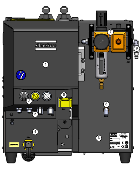
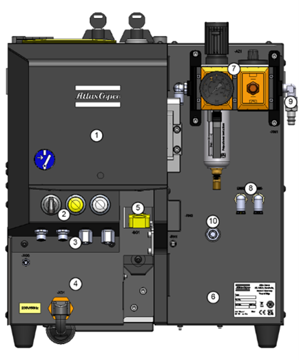
No. | Description | Function |
1 | Housing |
|
2 | Controls | Rotary Switch: Automatic or Bit Change mode. Illuminated Push Button: Error display, acknowledge errors. Status light. |
3 | Connections | Connection to the Power Focus 6000, start signal for the Screw Feeding Tightening Module, and other connections. |
4 | Housing for power supply | Control voltage and IEC Connector for mains connection. |
5 | Ring Sensor | Bushing for the Feeding Tube, the sensor detects outgoing screws to the Screw Feeding Tightening Module. |
6 | Housing | Electrical and pneumatic components. |
7 | Maintenance Unit | Pressure reducer with Shut-Off valve and filter. |
8 | Air Connections | Pneumatic Forward and Return Stroke connection between the Screw Feeding Tightening Module and the Screw Feeding Unit, or the supply to the Valve Control Unit (VCU). |
9 | Air supply | Connection to the compressed air supply. |
10 | Trigger Input Connector | Connection to the tool trigger input. |
The feeding process
The screws are filled into the Screw Container via the Filling Hatch.
From the Screw Container, the screws reach the Step Conveyor Unit and are transported upwards via movable steps.
The screws fall into the V-block of the Linear Guide (hanging from the collar), where they are guided into the Separating Unit.
The separation process
When a screw is required in the Screw Feeding Tightening Module, a single screw is separated out from the fasteners aligned on the Linear Guide.
The separated screw is blown into the Screw Feeding Tightening Module.


