EP8PTX45 SR10
Impulse Nutrunner
Safety and operating instructions
Safety instructions
Warning
Make sure you are familiar with the operating instructions before you use this machine.
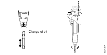
Before making any adjustments (e.g. setting the torque, changing bits) disconnect the machine from the compressed air line.
The machine, together with any attachments and accessories, must never be used for anything other than the designed purpose.
Use power sockets only. For safe and economic use - replace worn sockets.
Check that the power socket is properly fastened - replace the square drive retainer when necessary.
Keep your fingers away from the power socket during operation to avoid injury.
Never work without protective goggles.
Avoid unnecessary idling.
When using a suspension yoke, check that it is in good condition and correctly fastened.
Warning
Disassembly and assembly precautions
The rotor blades (vanes) in the tool contains PTFE. The normal health and safety recommendations concerning PTFE must be observed when handling these rotor blades. Particles from wear of blades might be found in the machine housing or on the blades. Make sure that these particles do not get in contact with open fire. Wash your hands before smoking since PTFE-particles heated by glow can produce fumes which may cause an allergic reaction.
General information
EC DECLARATION OF CONFORMITY
We, Atlas Copco Industrial Technique AB,
S-105 23 STOCKHOLM, SWEDEN declare that the product (with name,
type and serial number, see front page) is in conformity with the
following Directive(s):
2006/42/EC
Harmonised standards applied:
EN ISO 11148-6:2012
Technical file available from:
Quality Manager, Atlas Copco
Industrial Technique, Stockholm, Sweden
Stockholm, 1 July 2013
Tobias Hahn, Managing Director
Signature of issuer

Installation
Installation of vibrating tools
It is recommended that a minimum length of 300 mm of flexible hose for compressed air is inserted between a vibrating tool and the quick-action coupling.
Air quality
For optimum performance and maximum machine life we recommend the use of compressed air with a maximum dew point of +10°C. We also recommend the installation of an Atlas Copco refrigeration-type air dryer.
Use a separate air filter of type Atlas Copco FIL. This filter removes solid particles larger than 15 microns and also removes more than 90 % of liquid water. The filter must be installed as close as possible to the machine/equipment and prior to any other air preparation unit such as REG or DIM (please see Air Line Accessories in our main catalogue). Blow out the hose before connecting.
Models which need air lubrication:
The compressed air must contain a small quantity of oil.
We strongly recommend that you install an Atlas Copco oil lubricator (DIM). This should be set according to air consumption by the air line tool according to the following formula:L = Air consumption (litre/s)
D = Number of drops per min (1 drop = 15 mm3)
L* 0.2 = D
this applies to the use of long work cycle air line tools. A single point lubricator type Atlas Copco Dosol can also be used for tools with short running cycles.
Information about Dosol settings may be found under Air Line Accessories in our main catalogue.
Lubrication-free models:
In the case of lubrication-free tools it is up to the customer to decide on the peripheral equipment to be used. However, it is no disadvantage if the compressed air contains a small quantity of oil e.g. supplied from a fog lubricator (DIM) or Dosol system.
Note – This does not apply to turbine tools, which should be kept oil free.
Compressed air connection
The machine is designed for a working pressure of 6–7 bar = 600–700 kPa = 87–102 psi.
Blow out the hose before connecting.
Installation proposal
Choosing the correct couplings, hose and clamps can be a troublesome digging into details. To save your time and to ensure correct capacity of the airline installation, from the tapping point to the tool, we offer you an installation proposal.

For more information please read, Atlas Copco Industrial Power Tools catalogue Ordering No. 9837 3000 01.
Handling
Setting of tightening torque
The adjusting screw (the slotted screw) is the only screw that initially should be adjusted.
Start at a low torque adjustment and gradually increase the setting until you reach the desired torque level.
Use of a machine over recommended maximum torque might result in improper function and faster wear.
Always check the setting and make reference setup on your actual joint.
see Service Instructions.
Test method - Static or Dynamic
A static torque measurement is recommended for the ErgoPulse machines.
If dynamic torque measurement with an electronic inline torque transducer is used, always verify your measurement result by a static check with a torque wrench (electronic).
For more information, read Atlas Copco "Pocket Guide to Pulse Tools". Ordering No. 9833 1225 01.
Maintenance
For maximum performance
At tough working conditions – soft joints and max. setting – lubrication of the air is recommended.
With extreme dry air the service life of vanes and machine performance might be reduced. A daily supply of 0.1 – 0.2 ml oil into the machine inlet will improve the machine performance. Alternatively consider an automatic lubricator device, Atlas Copco oil fog lubricator DIM, or single point lubricator DOS, which will improve the machine performance.
Refill the pulse-unit with oil
For further information pls see - Service Instructions.
For optimum machine performance the pulse unit must be correctly filled with oil. Due to a possible microleakage of oil from the pulse unit, it could be necessary to refill the unit between the regular overhaul intervals. The frequency of this procedure depends on the type of application, number of cycles, tightening time etc. An accurate refill of the pulse unit gives long service intervals.
Too much oil in the pulse unit implies a low pulse frequency and slow tightening.
Too little oil in the pulse unit implies a high pulse frequency and there will be a risk of a decreasing tightening torque. In particular at the first tightening after a break the machine might race.
Use Hydraulic Oil : 22 cST / 40 °C (ISO VG22).
Running the machine with too little oil may damage the pulse unit.
After the refill – Check the tightening torque, see Service instructions.
Rust protection and internal cleaning
Water in the compressed air, dust and wear particles cause rust and sticking of vanes, valves etc. An air filter should be installed close to the machine (se 'Air quality'). Before longer standstills, flush with oil (some drops) into the air inlet, run the machine for 5-10 seconds when absorbing the oil in a cloth.
Service instructions
Overhaul and preventive maintenance is recommended at regular intervals once per year or after maximum 250.000 tightening depending on which occurs sooner. More frequent overhaul may be needed, specially replacing of oil in the pulse unit, if used at high torque and long tightening times. If the machine is not working properly, it should immediately be taken away for inspection.
The strainer at the air inlet and the exhaust silencer should be cleaned frequently or replaced in order to prevent clogging, which decreases the capacity.
At the overhauls, all parts should be cleaned accurately and defective or worn parts should be replaced.
All o-rings should be greased before assembling; especially important are the o-rings in the pulse unit.
Disassembling /assembling
It is important that the machines threaded connections are tightened properly; i.e. in accordance with the specifications on the exploded views.
Cleaning
Clean all parts, not electrical, thoroughly in white spirit or similar cleaning agent. To prevent clogging and decreased power, it could be necessary to clean the strainer (if used) and the exhaust filter between the overhauls.
Inspection
After the cleaning, inspect all parts. Damaged and worn parts should be replaced.
Lubrication
Lubricate specially gears, valve and clutch with grease containing molybdenum disulphide (e.g. Molykote BR2 Plus). Lubricate o-rings and threaded connections with grease before assembling.
Grease Guide ErgoPulse
Brand | General purpose Bearings | Motor shaft | Air Lubrication |
|---|---|---|---|
BP | Energrease LS-EP2 |
| Energol E46 |
Castrol | Spheerol EP L2 |
|
|
Esso | Beacon EP2 |
| Arox EP46 |
Q8 | Rembrandt EP2 |
| Chopin 46 |
Mobil | Mobilegrease XHP 222 |
| Almo oil 525 |
Shell | Alvania EP2 |
| Tonna R32 |
Texaco | Multifak EP2 |
| Aries 32 |
Molycote |
| BR2 Plus |
|
Useful information

Log in to Atlas Copco www.atlascopco.com
You can find information concerning our products, accessories, spare parts and published matters on our website.
Ergonomic guidelines
Consider your workstation as you read through this list of general ergonomic guidelines and see if you can identify areas for improvement in posture, component placement, or work environment.
Take frequent breaks and change work positions frequently.
Adapt the workstation area to your needs and the work task.
Adjust for convenient reach range by determining where parts or tools should be located to avoid static load.
Use workstation equipment such as tables and chairs appropriate for the work task.
Avoid work positions above shoulder level or with static holding during assembly operations.
When working above shoulder level, reduce the load on the static muscles by reducing the weight of the tool, using for example torque arms, hose reels or weight balancers. You can also reduce the load on the static muscles by holding the tool close to the body.
Make sure to take frequent breaks.
Avoid extreme arm or wrist postures, particularly for operations requiring a degree of force.
Adjust for convenient field of vision by minimizing movement of the eyes and head during the work task.
Use the appropriate lighting for the work task.
Select the appropriate tool for the work task.
Use ear protection equipment in noisy environments.
Use high-quality inserted tools or consumables to minimize exposure to excessive levels of vibration.
Minimize exposure to reaction forces.
When cutting:
A cut-off wheel can get stuck if the wheel is either bent or if it is not guided properly. Make sure to use the correct flanges for cut-off wheels and avoid bending the wheel during cut-off operation.
When drilling:
The drill might stall when the drill bit breaks through. Makes sure you use support handles if the stall torque is too high. The safety standard ISO11148 part 3 recommends using something to absorb the reaction torque above 10 Nm for pistol grip tools and 4 Nm for straight tools.
When using direct-driven screw or nutrunners:
Reaction forces depend on tool setting and joint characteristics. The ability to bear reaction forces depends on the operator’s strength and posture. Adapt the torque setting to the operator's strength and posture and use a torque arm or reaction bar if the torque is too high.
Use dust extraction system or mouth protection mask in dusty environments.
Country of origin
Please refer to the information on the product label.
Spare parts
Parts without ordering number are not delivered separately for technical reasons.
The use of other than genuine Atlas Copco replacement parts may result in decreased tool performance and increased maintenance and may, at the company option, invalidate all warranties.
Warranty
Contact the Atlas Copco sales representative within your area to claim a product. Warranty will only be approved if the product has been installed, operated and overhauled according to the Operating Instructions.
Please also see the delivery conditions applied by the local Atlas Copco company.
ServAid
ServAid is a utility for providing updated product information concerning:
- Safety instructions
- Installation, Operation and Service instructions
- Exploded views
ServAid facilitates the ordering process of spare parts, service tools and accessories for the product of your choice. It is continuously updated with information of new and redesigned products.
You can use ServAid to present content in a specific language, provided that translations are available, and to display information about obsolete products. ServAid offers an advanced search functionality of our entire product range.
ServAid is available on DVD and on the web:
http://servaidweb.atlascopco.com
For further information contact your Atlas Copco sales representative or e-mail us at:
servaid.support@se.atlascopco.com
Safety Data Sheets MSDS/SDS
The safety data sheets describes chemical products sold by Atlas Copco.
For more information, consult the website
http://www.atlascopco.com/.
Choose Products - Safety
Data Sheets, and follow the instructions on the page.
Technical data
Technical data
Noise and vibration emission
Noise (in accordance with ISO15744) | dBA |
|---|---|
Sound pressure level | 81 |
Sound power level | 92 |
Uncertainty | 3 |
Vibration total value, valid from 2010 | m/s2 |
|---|---|
Vibration value | 7 |
Uncertainty | 1.2 |
Noise and Vibration Declaration Statement
These declared values were obtained by laboratory type testing in accordance with the stated standards and are suitable for comparison with the declared values of other tools tested in accordance with the same standards. These declared values are not adequate for use in risk assessments and values measured in individual work places may be higher. The actual exposure values and risk of harm experienced by an individual user are unique and depend upon the way the user works, the workpiece and the workstation design, as well upon the exposure time and the physical condition of the user.
We, Atlas Copco Industrial Technique AB, cannot be held liable for the consequences of using the declared values, instead of values reflecting the actual exposure, in an individual risk assessment in a work place situation over which we have no control.
This tool may cause hand-arm vibration syndrome if its use is not adequately managed. An EU guide to managing hand-arm vibration can be found by accessing http://www.pneurop.eu/index.php and selecting 'Tools' then 'Legislation'.
We recommend a programme of health surveillance to detect early symptoms which may relate to noise or vibration exposure, so that management procedures can be modified to help prevent future impairment.
Service instructions
How to optimize the performance of your EP/EPP tool
How to optimize the performance of your EP/EPP tool
Recommended number of pulses
A pulse tool well suited for your application should reach the
target torque (with shut off) within 5-20 pulses.
The number of pulses can be measured with a IRTT and ACTA analyser.
The tightening time can also be used as a guide
to know if the tool is appropriate or not for your application:
≤ 1 sec. for tools up to 30Nm
≈1 sec. for tools up to 80Nm
≈2 sec. for tools up to 150Nm
≈5 sec. for tools up to 450Nm
≤ 10 sec. for tools up to 850Nm
If the target torque is achieved with less than 5 pulses (=short tightening time), the torque scatter will increase and it can be difficult to adjust to the right level, especially on hard joints.
If the target torque is achived with more than 20 pulses (=too long tightening time) the wear will increase and more frequent oil filling and service will be required. Too long tightening time, in combination with high production rate, may also result in excessive heating of the oil. In that condition the power will decrease with even longer tightening time and perhaps no shut off.
If the target torque is achieved with less than 5 pulses adress this issue by:
Decreasing the air pressure.
Reducing the speed by means of the AT or Trim valve.
If these measures are not possible or does not give acceptable results, a smaller tool can be a better choice.
If the target torque is achieved with more than 20 pulses adress this issue by:
Increasing the dynamic air pressure to 6-7 bar for standard EP tools or 5-6 bar for low pressure EP PTX-L tools.
Adjust the AT or Trim valve to give maximum power/speed.
If these measures are not possible or does not give acceptable results, a bigger tool can be a better choice.
If the air pressure has been changed the target torque must be measured again and adjusted if needed.
Air preparation
Air pressure
Adjusting the air pressure will have the following consequences:
Decreasing the air pressure will result in a slower but more accurate tool.
Increasing the air pressure will result in a faster but less accurate tool.
If the pressure from the airline is below 4.5 bar we recommend a tool from the EP PTX-L series, designed for low pressure installations.
Pressure regulators
We recommend using one pressure regulator for each tool. Make sure
to adjust the regulator to the lowest expected pressure on the line.
A pressure regulator will give the following advantages:
A stable air pressure which results in better accuracy.
Provides an easy way to adjust the power of the tool.
Air filters and air lubricators
We recommend using air filters and air lubricators, which will give
the following advantages:
Clean air without water and particles resulting in reduced tool wear and reduced risk of tool failure.
Will help to maintain the power and speed of the air motor over time.
Trim-RE or AutoTrim valve?
Use Trim-RE valve:
For applications where the tool is used to tighten screws with similar joint rate.
Use AutoTrim valve:
For applications where the tool is used to tighten both hard and soft joints.
Adjusting the AutoTrim valve
When using a tool with a AutoTrim valve make sure it is correctly adjusted, so the switching to full power is produced after the rundown and when the pulsing is starting.
For detailed instructions on how to adjust the AutoTrim valve see section Settings
Incorrect adjustment of the AutoTrim valve will result in:
Increased scatter.
Longer tightening time.
No shut off.
Service tools
Service tools are designed to make assembly and disassembly fast and easy with less risk of damaging parts in the process.
Correct tightening of parts is important to:
Optimize performance of the tool.
Minimize the risk of parts coming loose during operation.
You can find information about service tools and tightening data in the Spare part list section of the Product instruction.
Preventive maintenance
Preventive maintenance is recommended once per year or after a maximum of 250.000 tightening. A complete overhaul include:
Clean the pulse unit and change worn or damaged parts.
Clean the air motor and change worn or damaged parts.
Clean the silencer and the strainer of the inlet adapter, change the filter and change worn or damaged parts.
Clean the trigger and reversing valve and change worn or damaged parts.
General
Tightening of threaded connections
The tightening torques indicated in the exploded views list are established to achieve the correct clamping force and preventing the parts from coming loose. At service these parts must be able to open up without being destroyed. In special circumstances (depending on application and usage) the parts may however come loose after some time of operation. In such cases the torque could be increased 10-20% and if necessary some type of low or medium threadlocking fluid could also be applied.
Example

Operating Instructions
Inspection and lubrication of pulse unit

Fill the pulse unit with oil on a regular basis
It is necessary to fill the pulse unit with oil on a regular basis to compensate for micro leakage of oil between the outgoing shaft and the sealing o-ring. This is a normal occurence in hydraulic systems. Between overhauls regularly fill up the pulse unit with a small amount of oil without disassembling the pulse unit. The need for adding oil to the pulse unit will vary depending mainly on the number of tightening, torque level and number of pulses (tightening time). The need to add oil regularly to the pulse unit will normally decrease because the o-ring will seal better after a period of use. When the o-ring is changed the need to add oil regularly to the pulse unit may increase again.
Do not change the o-rings in the pulse unit except at the regular overhaul once per year or after a maximum of 250.000 tightening.
Negative effects of to little oil in the pulse unit:
Longer tightening time
No shut off
Decreasing torque
Increased scatter
Faster wear of the parts in the pulse unit
How to detect a low oil level in the pulse unit:
Increased pulse frequency
Low torque, no torque or abnormal torque changes
Very high pulsing speed, especially when the tool has not been used for a while.
Regular measurement of the pulse frequency is the best method to detect a low oil level in the pulse unit. If the pulse frequency has increased, preventive oil filling can be done before a low oil level in the pulse unit affects the function of the tool. The pulse frequency can be measured with a static torque transducer (SRTT) or an inline transducer (IRTT) connected to an ACTA 4000 instrument.
Recommended oil for the pulse unit
Recommended oil for the pulse unit:
SE2 Lubricant 45
Other hydraulic oils can also be used if they have the following characteristics: 22 cST/40ºC (ISO VG22). For example Mobil DTE-12M or Pennzoil Pennzbell AW22.
A bottle of SE2 Lubricant 45 oil and the required syringe or syringes are orderable as kits. Please see Service Kits for ordering numbers.
How to fill the pulse unit with oil
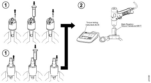
Method 1 (when using an ACTA and a Transducer):
This method is the fastest and will also give an optimized tool performance and result in the longest filling intervals. Fill the pulse unit with oil in accordance with the following instructions:
Position the pulse unit in a vice. Remove the oil plug positioned on either the front or the back of the pulse unit. Add a small amount of oil to the pulse unit.
Assemble the tool and measure the pulse frequency, for more details on measuring the pulse frequency see Static measurement with fixed transducer.
If the pulse unit frequency is in the specified range the amount of oil is correct.
If the pulse unit frequency is to low reduce some oil and measure the pulse frequency again.
If the pulse frequency is to high add some oil and measure the pulse frequency again.
Model
Free speed (r.p.m)
Pulse frequency (Hz)
Max Torque (minimum) (Nm)
EP 8 PTX SR10
5700
20 - 23
62
Method 2 (whitout an ACTA and Transducer):
This method is not as fast and accurate as using method 1. Fill the pulse unit with oil in accordance with the following instructions:
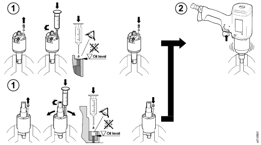
Position the pulse unit in a vice. Remove the oil plug positioned on either the front or the back of the pulse unit. Fill the pulse unit to 100% full. Assemble the oil plug.
Assemble the tool and run in reverse for 3-5 seconds.
Position the pulse unit in a vice. Remove the oil plug. Wait for all air bubbles to dissapear (approximatley 15 minutes) and the temperature to drop down to 20 degrees.
Fill the pulse unit to 100% full.
Reduce the oil in the pulse unit with a specified volume according to table using a 1 ml syringe. Assemble the oil plug.
Oil volume to be
reduced from 100%
Approx. oil volume
in pulse-unit
0.50 ± 0.05 ml
5 ml
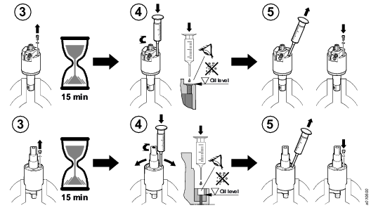
Check torque and shut off function, for procedure see Testing/Measuring.
If everything is in order the amount of oil is right.
If everything is not in order repeat from step one.
Position of stop pin
The “X” measurement is correctly set at our factory before delivery. Normaly the “X” measurement has to be adjusted only after that the parts concerned have been dismantled. If the accuracy is not as good as expected, check the position of the stop pin. The position of the stop pin is adjusted by turning the screw (see fig. below).
To ensure that the adjustment screw not will change position during operation, must the screw be sealed with "Loctite 290". Apply the "Loctite" before the adjustment is started.
The measurement “X” is hard to measure. It is possible to get the position by starting from “X” = zero. Hold the pulse unit vertically and check that the stop pin is covering a part of the centre hole (i.e. “X” is more than zero). Arrange the shut off valve in the centre hole (see fig. below). Adjust the screw until the valve drops down in the hole of the stop pin. In this position “X” is zero.
Place a gauge (i.e. a drill bit) with a diameter “D” according to table below in the hole. Then unscrew the screw untill the gauge is just tight in the hole. Note: the gauge must not be squeezed by the stop pin. Another way to get an appropriate “X” measurement is to unscrew the screw from the position “X” = zero. Unscrew the No. of turns given in the table below. The measurements given in the table will give a basic adjustment. Check the diameter “D” with a drill bit or similar. An increased “X” means a higher tightening torque and a decreased “X” means a lower tightening torque. It is possible to fine-adjust the tightening torque by turning the screw. Change with an 1/8 of a turn at a time.
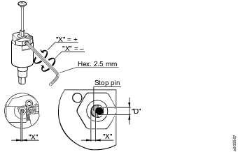
“D” | “X” | No.of turns to unscrew to get “X” |
|---|---|---|
1.65 mm | 1.40 mm | 1.75 |
Dismantling/inspection/assembly
Instructions for vane motor
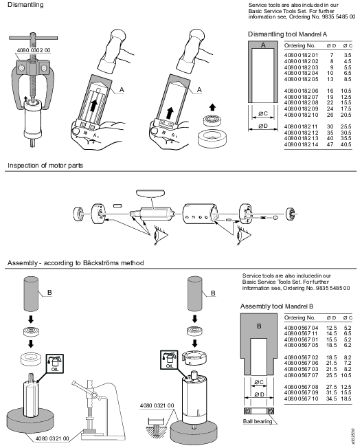
Test equipment/procedure
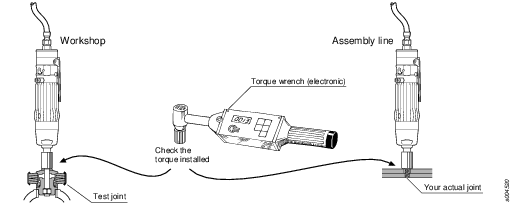
Static measurement (Recommended)
Dynamic measurement
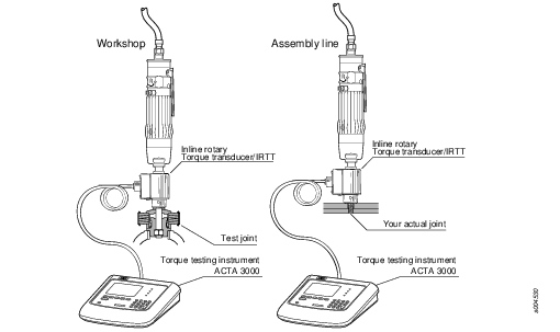
Always verify the setting on your actual joint.
Always verify the dynamic measurement on your actual joint by a static check with a torque wrench (electronic).
Static measuring with fixed transducers
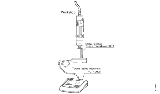
Test equipment and performance
Equipment:
Tachometer.
ACTA 3000.
SRTT transducer (secure the transducer firmly).
Test the free speed in the forward direction with the tachometer.
For AutoTrim versions make sure that the unreduced speed is measured (refer to section Function control - AutoTrim in the Trouble shooting schedule chapter of the service instruction for details).
Test the AutoTrim function.
Test the max torque and pulse frequency.
Set the filter frequency in ACTA 3000 to 850 Hz.
Measure the torque and pulse frequency in the reverse direction. Use a tightening time of approximately 1 second.
Check of shut-off mechanism.
Run the tool in the forward direction. If the shut-off mechanism is working properly the tool shuts off.
Test conditions
Temperature pulse unit: approx. 20° C.
Air pressure: 6,3 bar (90psi) dynamic
Hose size: 8 mm Hose length: 3 m
The tool should achieve the following values after maintenance:
Model | Free speed (r.p.m) | Pulse frequency (Hz) | Min. Torque (Nm) |
|---|---|---|---|
EP 8 PTX SR10 | 5700 | 20 - 23 | 62 |
Correct pulse frequency indicates that the air motor and the pulse unit are in good condition. If the pulse pulse frequency is to high - fill oil. If the pulse frequency is to low - reduce oil.
Test equipment - ACTA
Ordering No. | Description |
|---|---|
8092 1133 20 | ACTA 4000 B |
8092 1133 30 | ACTA 4000 QC |
8092 1133 40 | ACTA 4000 AA |
Test joints/Transducers
Bolt size | Torque range Nm | Torque rate Nm/rev. | Degrees at rated capacity | Service kit* |
|---|---|---|---|---|
M6 | 3-7 | 3 | 540 | 0211 1251 00 |
M6 | 5.5-10 | 5.5 | 540 | 0211 1251 00 |
M8 | - 15 | 10 | 540 | 4080 0788 80 |
M8 | 10 - 20 | 20 | 360 | 4080 0788 80 |
M10 | 20 - 30 | 20 | 210 | 4080 0789 80 |
M12 | 30 - 50 | 95 | 190 | 4080 0790 80 |
M14 | 50 - 100 | 200 | 180 | 4080 0791 80 |
M16 | 100 - 135 | 230 | 210 | 4080 0837 90 |
M16 | 135 - 200 | 130 | 540 | 4080 0866 92 |
M20 | 200 - 400 | 400 | 360 | 4080 0867 80 |
M24 | 400 - 800 | 800 | 360 | 4080 0876 80 |
* Including 2x screws, 2x nuts, 2x washers
In-line rotary torque transducers
Model | Hex inch | Drive square inch | Rated capacity Nm | ft lb |
|---|---|---|---|---|
IRTT 5-I06 | 1/4 |
| 5 | 4 |
IRTT 20-I06 | 1/4 |
| 20 | 15 |
IRTT 20-06 | 1/4 | 20 | 15 | |
IRTT 25-10 | 3/8 | 25 | 18 | |
IRTT 75-10 | 3/8 | 75 | 55 | |
IRTT 180-13 | 1/2 | 180 | 133 | |
IRTT 500-20 | 3/4 | 500 | 369 | |
IRTT 750-25 | 1 | 750 | 553 | |
IRTT 1400-25 |
| 1 | 1400 | 1033 |
In-line rotary torque/angle transducers
Model | Hex inch | Drive square inch | Rated capacity Nm | ft lb |
|---|---|---|---|---|
IRTT 2A-I06 | 1/2 |
| 2 | 1.5 |
IRTT 5A-I06 | 1/4 |
| 5 | 4 |
IRTT 20A-I06 | 1/4 | 20 | 15 | |
IRTT 20A-06 | 1/4 | 20 | 15 | |
IRTT 25A-10 | 3/8 | 25 | 18 | |
IRTT 75A-10 | 3/8 | 75 | 55 | |
IRTT 180A-13 | 1/2 | 180 | 133 | |
IRTT 500A-20 | 3/4 | 500 | 369 | |
IRTT 750A-25 |
| 1 | 750 | 553 |
IRTT 1400A-25 |
| 1 | 1400 | 1033 |
IRTT 3000A-38 |
| 1 1/2 | 3000 | 2200 |
Static reaction torque transducers (SRTT)
Model | Square drive in | Rated capacity Nm | ft lb |
|---|---|---|---|
SRTT 0.5-06 | 1/4 | 0,5 | 0,4 |
SRTT 2-06 | 1/4 | 2 | 1,5 |
SRTT 5-06 | 1/4 | 5 | 4 |
SRTT 25-10 | 3/8 | 25 | 18 |
SRTT 75-13 | 1/2 | 75 | 55 |
SRTT 180-13 | 1/2 | 180 | 133 |
SRTT 500-20 | 3/4 | 500 | 369 |
SRTT1400-25 | 1 | 1400 | 1033 |