Selector 6
Selector
Product information
General information
Safety signal words
The safety signal words Danger, Warning, Caution, and Notice have the following meanings:
|
DANGER |
DANGER indicates a hazardous situation which, if not avoided, will result in death or serious injury. |
|
WARNING |
WARNING indicates a hazardous situation which, if not avoided, could result in death or serious injury. |
|
CAUTION |
CAUTION, used with the safety alert symbol, indicates a hazardous situation which, if not avoided, could result in minor or moderate injury. |
|
NOTICE |
NOTICE is used to address practices not related to personal injury. |
Warranty
Product warranty will expire 12 months after the product is first taken into use, but will in any case expire at the latest 13 months after delivery.
Normal wear and tear on parts is not included within the warranty.
Normal wear and tear is that which requires a part change or other adjustment/overhaul during standard tools maintenance typical for that period (expressed in time, operation hours or otherwise).
The product warranty relies on the correct use, maintenance, and repair of the tool and its component parts.
Damage to parts that occurs as a result of inadequate maintenance or performed by parties other than Atlas Copco or their Certified Service Partners during the warranty period is not covered by the warranty.
To avoid damage or destruction of tool parts, service the tool according to the recommended maintenance schedules and follow the correct instructions.
Warranty repairs are only performed in Atlas Copco workshops or by Certified Service Partners.
Atlas Copco offers extended warranty and state of the art preventive maintenance through its ToolCover contracts. For further information contact your local Service representative.
For electrical motors:
Warranty will only apply when the electric motor has not been opened.
ServAid
ServAid is a portal that contains technical information for all hardware and software products such as:
- Safety Information including declarations, standards and directives
- Technical data
- Installation, Operation and Service Instructions
- Spare parts lists
- Accessories
ServAid is continuously updated and is available at:
https://servaid.atlascopco.com
For further information contact your local Atlas Copco representative.
Website
Log in to Atlas Copco: www.atlascopco.com.
You can find information concerning our products, accessories, spare parts and published matters on our website.
Safety Data Sheets MSDS/SDS
The safety data sheets describes chemical products sold by Atlas Copco.
For more information, consult the website:
www.atlascopco.com/sds
Country of origin
Please refer to the information on the product label.
Dimensional drawing
The dimensional drawings are applicable to all the selector versions for both wired and wireless applications.
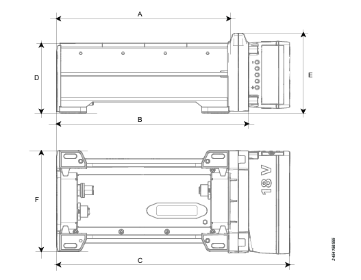
A | Overall length without mobility module | B | Overall length with mobility module |
C | Overall length with mobility module and battery | D | Height without mobility module |
E | Height with mobility module | F | Overall width |
All dimensions are given in mm.
Part number | Type | A | B | C |
|---|---|---|---|---|
8433 0611 04 | Socket 4 wired | 204 | NA | NA |
8433 0611 08 | Socket 8 wired | 408 | NA | NA |
8433 0611 09 | Bit 8 wired | 204 | NA | NA |
8433 0613 04 | Socket 4 wireless | NA | 228 | 278 |
8433 0613 08 | Socket 8 wireless | NA | 428 | 378 |
8433 0613 09 | Bit 4 wireless | NA | 228 | 278 |
Part number | Type | D | E | F |
|---|---|---|---|---|
8433 0611 04 | Socket 4 wired | 80 | NA | 120 |
8433 0611 08 | Socket 8 wired | 80 | NA | 120 |
8433 0611 09 | Bit 8 wired | 80 | NA | 120 |
8433 0613 04 | Socket 4 wireless | 80 | 95 | 120 |
8433 0613 08 | Socket 8 wireless | 80 | 95 | 120 |
8433 0613 09 | Bit 4 wireless | 80 | 95 | 120 |
Dimensional drawings
For information about the dimensions of a product, see the Dimensional drawings archive:
http://webbox.atlascopco.com/webbox/dimdrw
Overview
Selector overview
The selector is a holder for sockets and bits used together with a PF6 Controller and a tightening tool. LEDs on the selector are used to guide an operator to select the requested socket or bit that is to be used for a selected tightening.
The socket selector comes in different versions but with a common form factor.
Selector type | Description |
|---|---|
Socket 4 wired | The selector has 4 socket positions and has a wired Ethernet connection to the factory network, to a controller or to another device. |
Socket 4 wireless | The selector has 4 socket positions and has a wireless WLAN connection to the factory network and a wired Ethernet connection to another device. |
Socket 8 wired | The selector has 8 socket positions and has a wired Ethernet connection to the factory network, to a controller or to another device. |
Socket 8 wireless | The selector has 8 socket positions and has a wireless WLAN connection to the factory network and a wired Ethernet connection to another device. |
Bit 8 wired | The selector has 8 bit positions and has a wired Ethernet connection to the factory network, to a controller or to another device. |
Bit 8 wireless | The selector has 4 bit positions and has a wireless WLAN connection to the factory and a wired Ethernet connection to another device. |
Product data
Ethernet in connector (upstream) | M12 D-coded female connector |
Ethernet out (downstream) | M12 D-coded female connector |
External power in | 4 pin Kycon (DC DIN) male connector |
Power consumption | maximum 5 W |
Power in connector | AUX in |
Cable between devices | maximum 5 m |
Cable between network access point and device | maximum 50 m |
Cable between controller and device | maximum 50 m |
Daisy chain devices | Up to 32 |
Service port IP address | 169.251.1.1 |
Product data
Ethernet in connector (upstream) | M12 D-coded female connector |
Ethernet out (downstream) | M12 D-coded female connector |
External power in | 4 pin Kycon (DC DIN) male connector |
Power consumption | maximum 5 W |
Power in connector | |
Cable between devices | maximum 5 m |
Cable between network access point and device | maximum 50 m |
Cable between controller and device | maximum 50 m |
Daisy chain devices | Up to 32 |
Service port IP address | 169.251.1.1 |
Accessories
Accessory | Description | Part number |
|---|---|---|
Carry handle kit | A carry handle kit. Mounted into the grove on the backside of the selector. | 4222 3142 80 |
Protective cover | Protective cover to prevent scratches on other surfaces. | 4222 3192 70 (4 slot) 4222 3193 70 (8 slot) |
Daisy chain cable 4-4 | Power-over-Ethernet cable with M12 D-coded connectors in both ends. Short cable used for selectors with four socket positions. | 4222 3155 80 |
Daisy chain cable 8-8 | Power-over-Ethernet cable with M12 D-coded connectors in both ends. Long cable used for selectors with eight socket positions. | 4222 3155 82 |
Daisy chain cable 4-8 | Power-over-Ethernet cable with M12 D-coded connectors in both ends. Long cable used for selectors with eight socket positions to selector with four positions. | 4222 3155 81 |
Power battery | SRB type battery; Li-ion 18 V | 4211 6030 85 |
Power battery | SRB type battery; Li-ion 36 V | 4211 6030 86 |
Battery charger | SRB type battery Flex charger for 18-36 V together with power cord for 120 V / 60 Hz - 230 V / 50 Hz main supply. | 4211 6083 84 |
PF6000 adapter cable | Adapter cable for connecting earlier Power Focus 6000 models to a selector; one end with RJ45 connector and other end with comport connector. | 6500 9052 90 |
Power injector | Power injector and external power supply (MOXA-INJ24) | N/A |
Network cable | Connecting the socket selector to a network that is capable of supplying Power-over-Ethernet (PoE); one end with RJ45 connector, and the other end with male M12 D-coded connector. | N/A |
DC Power supply | An external power supply that is capable of supplying up to three selectors and which is rated for 24 V. | 8432 0840 00 |
Socket holder | 50 mm wide socket or bit holder. Needs an appropriate drilled hole before it is installed in the selector. | 4222 3114 20 |
DIN rail adapter kit | To mount the selector (using the groove on the backside) | 4222 3145 80 |
Socket holder high | 50 mm wide socket or bit holder, 50 mm high version. Needs an appropriate drilled hole before it is installed in the selector. | 4222 3114 21 |
Protective cover 4 | Protective cover for Socket 4 Wired | 4222 3192 70 |
Protective cover 8 | Protective cover for Socket 8 Wired | 4222 3193 70 |
Battery charger
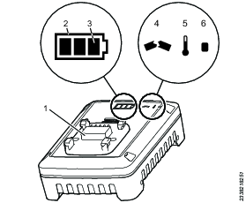
1 | Battery adapter | 2 | State of health indicator (SOH) |
3 | State of charge indicator (SOC) | 4 | Broken indicator |
5 | Temperature indicator | 6 | Power indicator |
Battery information
| Internal Lithium Ion Polymer | External Lithium Ion battery |
|---|---|---|
Manufacturer | Renata | Atlas Copco |
Type/Model | ICP422339PR | 5INR19/66 |
Voltage | 3,7V DC | 18V DC |
Capacity | 330mAh | 2.6Ah |
Socket selector description
The descriptions are applicable to all the selector versions for both wired and wireless applications.
The figures show all the key user interfaces for installation and operation of the selector. The descriptions are applicable to all versions. The wireless versions have a mobility module with a radio that also connects the battery. The wired versions
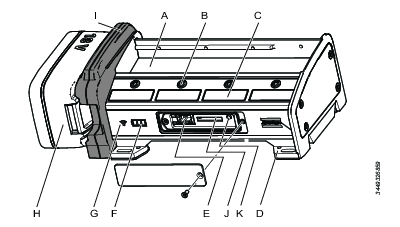
A | Space for socket holders | B | Indicator LEDs for the position |
C | Sticker area | D | Mounting holes in each corner |
E | Service port | F | Battery status LED (only available on wireless versions) |
G | WLAN status LED (only available on wireless versions) | H | Power battery (only available on wireless versions) |
I | Mobility module (only available on wireless versions) | J | Rapid Backup Unit (RBU) |
K | Function button |
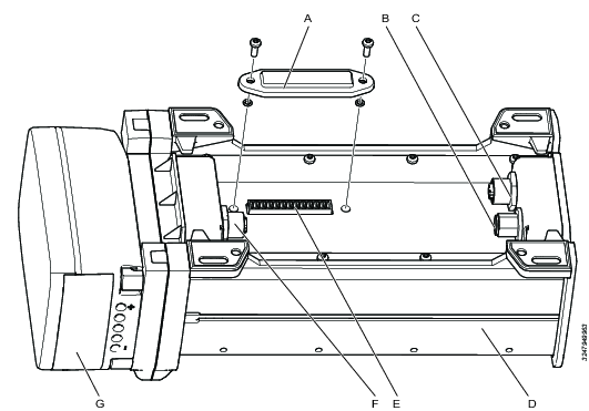
A | Connector cover | B | External DC power in; Kycon (DC DIN) connector |
C | PoE in, upstream connection; M12 D-coded female connector | D | Selector back side |
E | Digital input and output connector | F | PoE out, downstream connection; M12 D-coded female connector |
G | Battery |
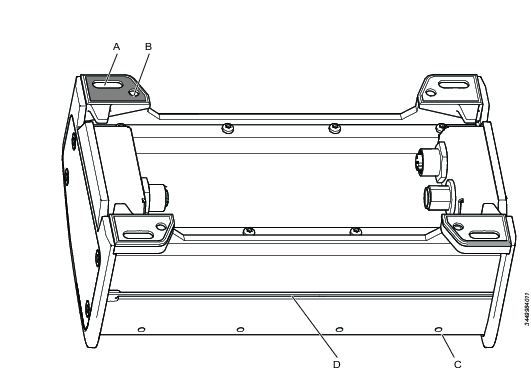
A | Holes 6 x 12 mm in each corner; accessible from above for horizontal installation | B | Threaded M4 holes in each corner; accessible from below for horizontal installation |
C | Socket holder screw | D | Groove for M4 square nut, for vertical installation |
Digital input and output connector
A connector for additional input and output signals is located under a cover at the bottom side of the selector. The digital out 1-4 are enabled when sockets 1-4 are prompted.
Currently, this functionality is only implemented on Digital Out. Digital Out is enabled when a socket position is prompted (LED blinking).
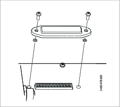
Pin number | Function |
|---|---|
1 | Digital input 1 |
2 | Digital input 2 |
3 | Digital input 3 |
4 | Digital input 4 |
5 | Common ground |
6 | Digital output 1 |
7 | Digital output 2 |
8 | Digital output 3 |
9 | Digital output 4 |
10 | Common ground |
11 | Output voltage, up to 24 V |
12 | Ground |
External digital output signals can only be supported if an external DC power supply is used. PoE and the power battery do not have enough capacity.
Indicator LEDs
The LED signals have the following functions:
Socket LEDs that guide the operator in the tightening work.
Battery status led used for portable solutions (only available on wireless versions).
Wireless connection status (only available on wireless versions).
Socket LEDs
There are two LED's for each socket or bit position. These LED's guide the operator to pick the correct socket or bit for the next tightening. The following LED lights can be shown.
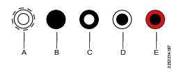
A | Outer and inner LED white and flashing | B | Both LED's switched off |
C | Inner LED steady white | D | Outer LED steady white |
E | Outer LED steady red |
More information about interpreting the LEDs is given in the Selector workflow section.
Battery status LEDs
Only available on wireless versions.
The battery status is displayed with three LEDs  when a battery is placed into the mobility module.
Three white LEDs indicates that more than 75 % battery capacity remains.
Two white LEDs indicates that less than 75% but more than 50 % battery capacity remains.
One white LED indicates that less than 50 % but more than 25 % battery capacity remains.
One red LED indicates that less than 25 % battery capacity remains and that the battery needs to be changed.
Blinking red LED indicates that the battery needs to be changed immediately.
If the battery is removed from the mobility module, these LEDs are all switched off.
Network status LED
Only available on wireless versions.
There is one single blue LED  to indicate the status of the WLAN connection:
If no wireless connection is detected, the LED is off.
If no wireless communication is established the LED is off.
If a wireless communication link is established between the selector and a network access point, the blue LED is blinking.
If communication is established between the selector and an assigned Virtual Station in the controller, the blue LED has a steady light.
If the battery is changed while the selector is assigned to a Virtual Station, the selector will retain the connection, showing a steady blue light.
Service interface
A service interface is located on the front of the socket selector. It is located beneath a cover that is fastened with a screw. The following features are available in the service interface:
One Rapid Backup Unit (RBU).
A function button.
A RJ45 connector.
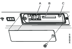
A | RJ34 Ethernet port | B | RBU slot |
C | Function button |
Function button
The function button clears all the user configurable parameters and set the to the factory default values when held down for five seconds while applying power to the selector.
RJ45 connector
This service connector is used to connect an Ethernet cable to a personal computer. The selector software contains a configuration interface (IP Address: 169.251.1.1). It is used to set up the network connection and to perform diagnostics and software loading.
Rapid Backup Unit
The RBU has the form factor of an SD card. This memory card contains all the current network configurations and settings. During the installation and configuration all the parameters are saved on the card. In case of a failure, it is a quick task to remove the card and put it into a new selector and all functionality remains the same.
This RBU card can not be used to anything else but storing the selector configuration data.
Service overview
Service recommendations
Preventive maintenance is recommended at regular intervals. See the detailed information on preventive maintenance. If the product is not working properly, take it out of service and inspect it.
If no detailed information about preventive maintenance is included, follow these general guidelines:
-
Clean appropriate parts accurately
-
Replace any defective or worn parts
Installation
Installation requirements
General Installation warnings
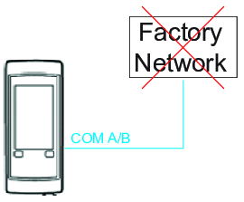
Do not connect the PF6000 to the factory network using COM Port A or B. These are to be used only for accessories.
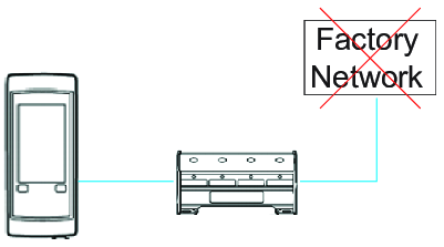
Do not connect the Selector to both a controller and the factory network.
Power connections
A socket selector can be powered in 3 different ways:
Atlas Copco Power Supply 8432 0840 00
Power-over-Ethernet (PoE) , that is supplied from the factory Ethernet network, from a controller or from an upstream device (injector or other selector).
An 18 V or 36 V Li-ion Atlas Copco tool battery of type SRB. The battery option is only applicable for models that are equipped with the mobility module for a wireless connection.
Daisy chain length | Battery type | |
|---|---|---|
18V | 36V | |
1 | 10h | 24h |
2 | 6h | 12h |
3 | 2h | 6h |
The power selection depends on the workplace environment and the available network topologies.
Power battery replacement
This section is only applicable for models that are equipped with the mobility module for a wireless connection.
If the selector is assigned to a Virtual Station and the battery is replaced, it the WLAN link is kept alive during the short battery switching time (with a maximum of 30 seconds).
Power over Ethernet
It is possible to use an Ethernet cable for communication and power feeding using the standardized Power-over-Ethernet (PoE) concept. A selector can be directly connected to a controller or a network that is PoE enabled, and the device does not need any external power supply.
When more selectors are needed, they can be interconnected in a daisy chain and use PoE. The first socket selector in a chain supplies the power to the downstream selectors. The power in the PoE link has limitations and it is possible to connect up to 3 socket selectors in a chain. If more than 3 selectors are used in a daisy chain, every 4th socket selector needs an additional Atlas Copco PSU to support PoE to another group of 3 selectors.
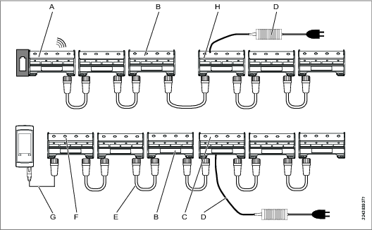
A | First selector in a daisy chain configuration, supplies power to downstream devices The first selector in a daisy chain has a wireless connection to the factory network | B | Selector number 3 in a downstream chain; last unit that can be powered by upstream unit number 1 with PoE |
C | Socket with external power, number 4 in the daisy chain Power must be supplied from an external DC source | D | Atlas Copco external power supply |
E | Link between socket selectors including communication and power using PoE connectivity | F | First selector in a daisy chain configuration, supplies power to downstream selectors The selector is powered from a controller or from a network with PoE capability |
G | PoE cable from controller A controller that is PoE enabled | H | Socket with external power, number 4 in the daisy chain Power must be supplied from an external DC source |
This concept is applicable regardless if the chain of socket selectors is connected to the factory network, directly connected to the controller or powered by a battery with a wireless connection.
Using too many selectors in a PoE daisy chain, i.e. using 4 or more socket selectors, will cause all selectors to enter a reboot cycle until the faulty configuration is fixed.
A socket selector that is battery powered can always be connected to an external DC power supply and operate normally. Connecting an external power supply to a battery powered selector, will not charge the battery as the selector has no integrated battery charger.
External DC power supply
A selector can always be connected to, and powered by, an external DC power supply regardless if it is installed and configured in a system architecture for PoE or battery power.
Old Power Focus 6000 controllers
The previously described scenario requires a controller that is equipped with PoE connector. Early controllers do not have this port.
A standard component, a PoE injector, combines the power with the ethernet communication. A special Atlas Copco supplied cable connects between the Power Focus controller com port and the RJ45 connector in the PoE injector. A standard cable with RJ45 and M12 connectors couples between the injector and the socket selector.
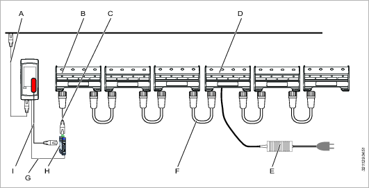
A | Controller connected to factory network | B | First socket selector in a daisy chain configuration; supplies power to 3 downstream selectors |
C | Standard cable between RJ45 and M12 connectors, supporting PoE | D | Socket selector number 4 in the daisy chain needs external power and can supply power through PoE to downstream devices |
E | Power supply unit for selector | F | Link between socket selectors including communication and power using PoE connectivity |
G | From 24V out screw terminal in PF6000 to the MOXA INJ-24 power supply in. | H | PoE injector; MOXA-INJ24 |
I | Adapter cable from controller com port to support ethernet communication to RJ45 connector Used for a controller that is not PoE enabled |
Installation height
The equipment's maximum installation height is 2 m.
Installation options and drill patterns
The installation options and the drill patterns are applicable to all the selector versions for both wired and wireless applications.
The selector has the following installation options:
Fixed installation, mounted on a vertical surface.
Mobile installation with a protective cover and/or carry handle.
Fixed installation, mounted from above.
Fixed installation, mounted from below.
Installing options from the backside

A | Oval holes, accessible from above or from below (up to M6) | B | Threaded M4 holes, accessible from below |
C | socket holder fastening screws | D | Groove into which M4 square nuts can slide |
The backside of the selector has a groove into which square M4 nuts can slide for mounting the selector from the backside.
A DIN rail adapter is available as a selector accessory that can be fastened into the groove.
Mobile installations
For mobile installations, the following selector accessories are available:
A carry handle kit. Mounted into the grove on the backside of the selector.
A protective cover. The selector is placed in a protective cover to avoid scratching other surfaces and to increase the selector's robustness.
Installing on a horizontal surface from above or from below
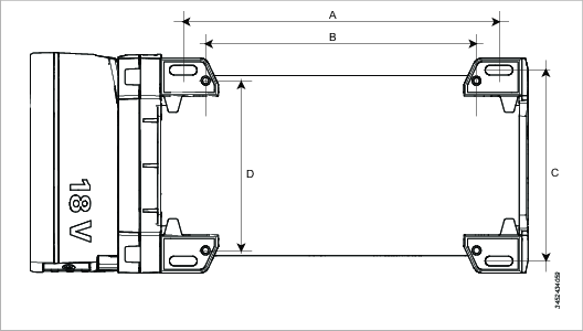
A | Distance between oval holes, accessible from above or from below | B | Distance between threaded M6 holes, accessible from below |
C | Distance between oval holes, accessible from above or from below | D | Distance between threaded M6 holes, accessible from below |
Each corner has an oval shaped hole 6 x 15 mm, for mounting the selector to a surface from above.
Each corner has a threaded M4 holes for mounting the selector to a surface from below.
All dimensions are given in mm.
Part number | Type | A | B | C | D |
|---|---|---|---|---|---|
8433 0611 04 | Socket 4 wired | 174 | 150 | 106 | 94 |
8433 0611 08 | Socket 8 wired | 374 | 350 | 106 | 94 |
8433 0611 09 | Bit 8 wired | 174 | 150 | 106 | 94 |
8433 0613 04 | Socket 4 wireless | 174 | 150 | 106 | 94 |
8433 0613 08 | Socket 8 wireless | 374 | 350 | 106 | 94 |
8433 0613 09 | Bit 4 wireless | 174 | 150 | 106 | 94 |
Selector connected with a WLAN link to the factory Ethernet network
In a scenario when multiple socket selectors are needed they can be interconnected in a daisy chain.
The chain of selectors can be connected to the controller in different ways and depends on the workplace environment and the available network topologies.
More information about connections and power consideration can be found in the section Power connections.
This scenario describes how the socket selector is connected to the factory Ethernet using a wireless connection.
The figure shows an architecture with daisy chained connectors. If only one selector is used, the same connection and configuration is applicable a for the first device.
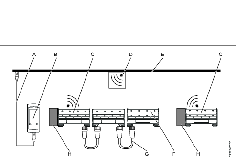
|
A |
Controller connected to the factory Ethernet network |
B |
Power Focus 6000 controller |
|
C |
Battery powered selector First selector in a daisy chain |
D |
WLAN access point |
|
E |
Factory Ethernet network |
F |
Last selector in a daisy chain |
|
G |
Link cable between selectors, creating the daisy chain |
H |
Power battery |
The socket selector can be powered by an external power supply or from a battery.
The figure shows two separate daisy chains. Each chain is connected to the factory network. The address of the chain is defined by the IP address of the first selector in the chain. The IP address can be either a fixed IP address or a dynamic address provided by a DHCP server on the network. IP addresses and network architecture is managed by the factory IT department.
It is possible to create long daisy chains of devices using the PoE connection. The PoE architecture has power limitations that require external power for every forth selector. Se the section Power connections for more details.
Installation instructions
Socket holder installation
The selector is delivered with four or eight socket holders. The socket holder is placed above each sensor position and is made of plastic.
Installing socket holders
The socket holder slides into two grooves, one on the front and one in the rear.
To install the socket holders in the selectors, perform the following steps:


Pick the left most holder position and insert it in the right most position.
Insert the holder into right most position from above. Notice the difference between the front and rear side. The hole must be above the sensor.
Tilt the holder downwards with the front side.
Move the holder downwards and forward, so that the selector front rail enters the holder groove.
Lower the holder rear end, so it rests on the selector.
Slide the holder towards the left. Make sure the rear end rail enters the rear groove of the holder.
Repeat the above steps with all the selector holders and make sure to place them in their correct positions.
Fasten all the allen screws from the backside to secure the socket holders in their positions.
Removing socket holders
It is up to the user to drill holes in the socket holder in the right place with the desired dimension.
Do not drill socket holes with the socket holders installed in the selector
To remove the socket holders from the selectors, perform the following steps:
Remove the 2 mm allen screws in the back of the selector.
Remove the right most socket holder by lifting the rear end and sliding the holder upwards and backwards.
Slide the remaining socket holders to the right most position and remove them in the same way.
Mark the socket holes and drill holes slightly larger than the socket.
Bit placement
Always place bits with the sharp end facing up.
The selector sensors are sensitive to the presence of metal. Depending on the mix of metal and plastic used, the sensors may behave differently.
Socket holder drilling
Do not drill the holes in the socket holder while the holder is installed in the selector.
The sensor elements are located in the bottom of the selector. For accurate detection it is important that the socket holder is directly above the sensor. Two options are available for drilling:
One single socket or bit in the center of the holder. This is shown by the center hole in the figure.
Two sockets or bits placed side by side in the holder. This is shown by the two outer holes in the figure.
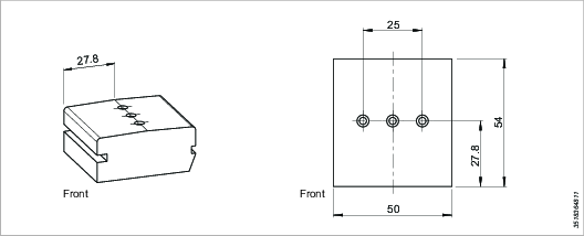
Recommended drilling
Material remaining between holes shall not be less than 3 mm.
Material remaining between hole and outer edge shall not be less than 3 mm.
Hole diameter shall be 1 mm larger than the bit or socket dimension.
For a single hole, the socket size can be maximum 43 mm.
For two holes, the socket size can be maximum 19 mm.
Selector interconnect
Sockets are connected or interconnected through cable connectors at the bottom from below.
All cables are connected before the selector is installed.
Interconnection cables with proper length are available from Atlas Copco. Cable ducts are available along the front and rear and sides of the selector.
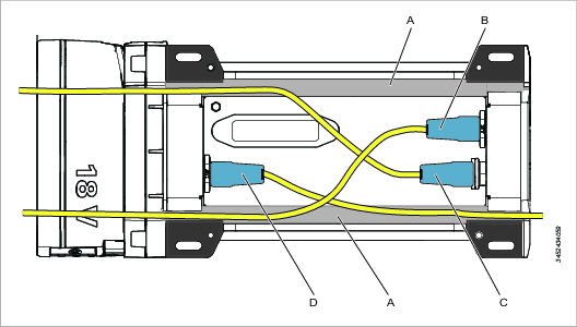
A | Cable duct | B | Ethernet-in upstream cable to connector M12 D-coded, female connector in the selector |
C | External DC power Kycon 4 pin male connector in the selector (DC DIN) | D | Ethernet-out downstream cable to connector M12 D-coded, female connector in the selector |
In an application that uses one single wireless selector, no interconnections are needed.
Initial configuration
Connecting the selector to a PC for configuration
Initial configuration of the socket selector is done before it is installed in its working environment. All settings and functions can be verified and tested.
The configuration is saved in the Rapid Backup Unit ( RBU) , which is a dedicated memory with a SD card form factor.
Default setting for a selector is set to PF6000 directly, i.e. a wired connection. When using a wired connection, or when connecting via accessory, no extra configuration is required.
Disconnect all power from the selector.
Open the service port cover on the selector. The cover is secured by a Torx 10x50 screw.
Connect an ethernet cable between a PC and the RJ-45 connector in the service interface.
Verify that the RBU is correctly inserted into the SD card slot, or insert the card.
Connect power to the selector by connecting an external power supply or by connecting a battery.
Open a web browser window in the PC.
Type the web address 169.251.1.1 and press the Enter key. The web server in the selector will respond and show the selector web interface.
Select the Settings icon
 in the left menu bar. The settings workspace shows the configuration menus.
When all configurations are done, verified and saved:
Leave the RBU in the SD card slot.
Remove the ethernet cable.
Close the cover and secure with the screw.
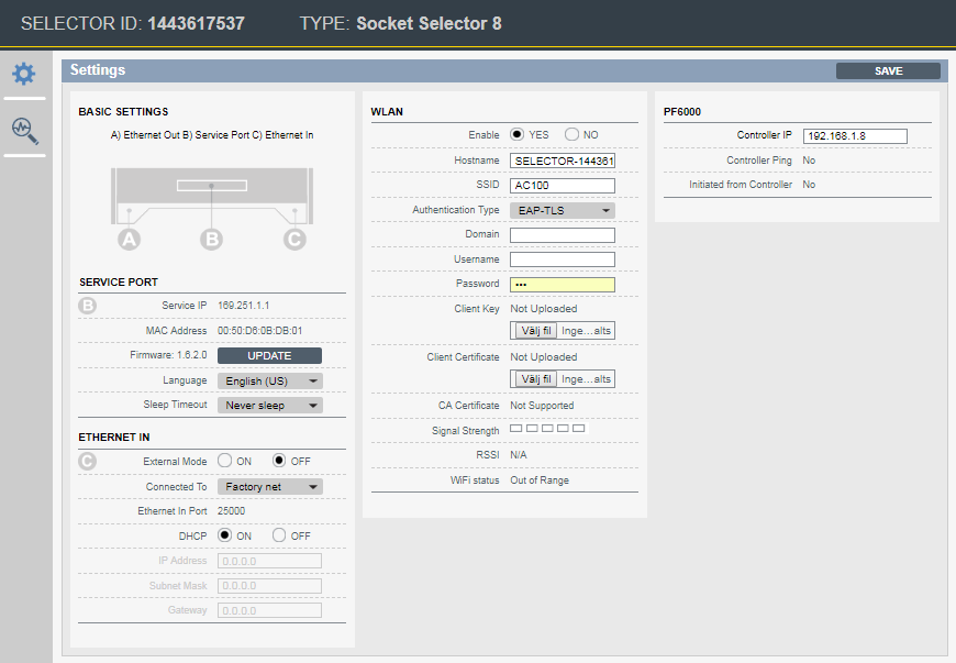
Network connection overview
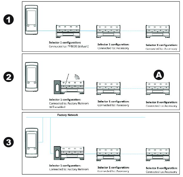
WLAN Enable | Factory net | PF6000 (direct connection) | Accessory (daisy chain) |
|---|---|---|---|
Yes | Yes (2) | No | No |
No | Yes (3) | Yes (1) | Yes (A) |
Encryption Type overview
The following encryption types can be chosen in the drop-down:
WEP 64 (64 bit Wired Equivalent Privacy)
WEP 128 (128 bit Wired Equivalent Privacy)
PSK/TKIP (Pre-shared Key/Temporal Key Integrity Protocol)
AES/CCMP (Advanced Encryption Standard/Cipher Mode with Cipher Block Chaining Message Authentication Protocol)
Authentication
The following authentication methods are supported:
WPA (Wireless Protected Access - used in combination with PSK/TKIP)
WPA2 (More advanced version of WPA - used in combination with AES/CCMP)
LEAP (Lightweight Extensible Authentication Protocol)
PEAP (Protected Extensible Authentication Protocol)
EAP/TLS (Extensible Authentication Protocol/Transfer Security Layer)
WLAN configuration required per authentication type
Authentication Type | Hostname | SSID | Password | User Name | Domain | Client Key/ | CA Certificate |
|---|---|---|---|---|---|---|---|
WPA/WPA2-PSK | Optional | Yes | Yes | No | No | No | No |
LEAP | Optional | Yes | Yes | Yes | Yes | No | No |
PEAP | Optional | Yes | Yes | Yes | Yes | No | Not supported |
EAP-TLS | Optional | Yes | Yes | Yes | Yes | Yes | Not supported |
Authentication configuration will be encrypted and stored on the RBU. For security reasons, selecting another Authentication Type will delete the previous configuration from the RBU.
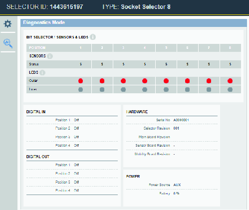
Operation
Ergonomic guidelines
Consider your workstation as you read through this list of general ergonomic guidelines and see if you can identify areas for improvement in posture, component placement, or work environment.
Take frequent breaks and change work positions frequently.
Adapt the workstation area to your needs and the work task.
Adjust for convenient reach range by determining where parts or tools should be located to avoid static load.
Use workstation equipment such as tables and chairs appropriate for the work task.
Avoid work positions above shoulder level or with static holding during assembly operations.
When working above shoulder level, reduce the load on the static muscles by reducing the weight of the tool, using for example torque arms, hose reels or weight balancers. You can also reduce the load on the static muscles by holding the tool close to the body.
Make sure to take frequent breaks.
Avoid extreme arm or wrist postures, particularly for operations requiring a degree of force.
Adjust for convenient field of vision by minimizing movement of the eyes and head during the work task.
Use the appropriate lighting for the work task.
Select the appropriate tool for the work task.
Use ear protection equipment in noisy environments.
Use high-quality inserted tools or consumables to minimize exposure to excessive levels of vibration.
Minimize exposure to reaction forces.
When cutting:
A cut-off wheel can get stuck if the wheel is either bent or if it is not guided properly. Make sure to use the correct flanges for cut-off wheels and avoid bending the wheel during cut-off operation.
When drilling:
The drill might stall when the drill bit breaks through. Makes sure you use support handles if the stall torque is too high. The safety standard ISO11148 part 3 recommends using something to absorb the reaction torque above 10 Nm for pistol grip tools and 4 Nm for straight tools.
When using direct-driven screw or nutrunners:
Reaction forces depend on tool setting and joint characteristics. The ability to bear reaction forces depends on the operator’s strength and posture. Adapt the torque setting to the operator's strength and posture and use a torque arm or reaction bar if the torque is too high.
Use dust extraction system or mouth protection mask in dusty environments.
Operating instructions
Selector operation and workflow
The selector indicator LEDs guide the operator through a tightening task. The LEDs show which socket to pick and put on the tool for the next tightening.
The indicator LEDs can be controlled by the connected controller and its program using the Auto mode, or by an external control unit, using the External mode.
The external control unit can be a PLC or any other factory management system connected to the Power Focus 6000 controller with an Open protocol or Fieldbus communication link.
If using External mode to control the LEDs, the controller acts only as a relay station. The external control unit sends commands to the Power Focus 6000 about selector LED commands and the controller forwards these commands to the selector.
If using Auto mode, the controller tightening program, the batch sequence configuration and the socket selector device configuration control the LEDs.
The Power Focus 6000 controller can have many selector configurations. Each configuration may have a different number of active sockets, regardless if they are used or not. Place sockets in all the used positions.
If bits are used, place the sharp end upwards. This is to protect the sensor at the bottom of the holder.
There are two LED's for each socket or bit position. These LED's guide the operator to pick the correct socket or bit for the next tightening. The following LED patterns can be shown.

A | Outer and inner LED white and flashing | B | Both LED's switched off |
C | Inner LED steady white | D | Outer LED steady white |
E | Outer LED steady red |
Depending on the configuration in the controller, an operator can perform tightenings in a fixed order or in a free order pattern. Examples will describe both correct an faulty scenarios.
Rules for indicator LEDs - fixed order tightening
A task is selected by the controller and the selector requests that one particular socket is lifted. The request signal is a white flashing LED (inner and outer LEDs)
Action | Pos 1 | Pos 2 | Pos 3 | Pos 4 |
|---|---|---|---|---|
Lift the requested flashing socket. |
The correct requested socket is lifted. The tightening can start
Action | Pos 1 | Pos 2 | Pos 3 | Pos 4 |
|---|---|---|---|---|
The correct socket (2) is lifted. The tightening can start. |
The wrong socket is lifted. The selector indicates the lifted socket and continues to request the desired socket. The tightening can not start until the wrong socket is replaced and the correct socket is lifted.
Action | Pos 1 | Pos 2 | Pos 3 | Pos 4 |
|---|---|---|---|---|
The wrong socket (1) is lifted. The requested socket (2) is flashing. |
Two sockets are lifted and no tightening can be performed. The tightening can not start until the wrong socket is returned.
Action | Pos 1 | Pos 2 | Pos 3 | Pos 4 |
|---|---|---|---|---|
Both the correct socket (2) and wrong socket (1) are lifted. The tightening can not start. |
An error case, lighting up a red light, only occurs if a tightening is performed, the socket is returned and is picked up again. This applicable for single tightening or when a batch is completed.
Tightening position 2 has been completed and returned. Position 3 is requested. Lifting position 2 again, results in a error showing a red light as it is completed. Lifting position 1, results in a steady white as this position is not done and not requested. The tightening can not start until the erroneous sockets are returned and the requested socket (3) is lifted.
Action | Pos 1 | Pos 2 | Pos 3 | Pos 4 |
|---|---|---|---|---|
A tightening or batch with sockets 2 has been completed and returned. It is now lifted again. Socket 3 is requested. Socket 1 is also lifted. The tightening can not start. |
Rules for indicator LEDs - free order tightening
The selector requests that one of several sockets is lifted (free order tightening). The request signal is a white flashing LED (inner and outer LEDs). The tightening program is selected when an acceptable socket is lifted.
Action | Pos 1 | Pos 2 | Pos 3 | Pos 4 |
|---|---|---|---|---|
Lift a socket among the flashing options. |
One socket is lifted and a tightening program is selected. The tightening can start. The remaining request LEDs are switched off.
Action | Pos 1 | Pos 2 | Pos 3 | Pos 4 |
|---|---|---|---|---|
A socket (3) is lifted. The tightening can start. |
Two sockets are lifted and no tightening program is selected. The tightening can not start until one socket is returned. No other sockets are requested and those LED's are switched off.
Action | Pos 1 | Pos 2 | Pos 3 | Pos 4 |
|---|---|---|---|---|
Two sockets (2 and 3) are lifted. The tightening can not start. |
An error (red light) only occurs if a tightening is completed, the socket is returned and is picked up again. This is applicable for a single tightening or when a batch is completed. A free order batch sequence allows sockets to be returned and picked up and will not show an error until the batch is completed.
In a free order tightening, position 3 is completed and the socket has been returned. Socket 1 or 2 is requested - first row.
Position 3 is picked up again. As this batch is completed, an error will show. The remaining LEDs are switched off - second row.
Lifting position 1, results in a steady white as this position is not completed. The tightening can not start until the erroneous socket is returned - third row.
Action | Pos 1 | Pos 2 | Pos 3 | Pos 4 |
|---|---|---|---|---|
A tightening or batch with sockets 3 has been completed and returned. Positions 1 or 2 are requested | ||||
A tightening or batch with sockets 3 has been completed and returned. It is now lifted again. An error is indicated | ||||
Two sockets are lifted. One is an error and one is an option to use. A tightening can not be performed until one socket is returned. | ||||
One socket is selected, a tightening program is selected and a tightening can be performed. |
Definitions
Certain definitions must be known to be able to follow the examples. For detailed information see the Power Focus 6000 configuration manual.
Parameter | Description |
|---|---|
Batch | A number of tightenings that use the same tightening program and the same socket. |
Batch sequence | A number of batches were each batch has a different tightening program and were the batch may have a different socket. |
Batch counter | A counter that keeps track of each tightening within a batch and batch sequence. The total count summarizes all tightenings within a batch sequence. |
Fixed order | The tightenings have to be performed in a fixed order as it is defined in the controller configuration. The LEDs on the selector will guide the operator through the process. |
Free order | The operator is free to choos the order of tightenings. The LEDs on the selector show the available options. |
external mode | The selector LEDs are controller by an external master that communicates through the controller. |
Auto mode | The selector LEDs are controller by the program in the Power Focus 6000 controller. |
Operator task example
At an imaginary station, an operator has to perform the following task:
Use program AA three times with socket number 2.
Use program BB two times with socket number 3.
Use program CC one time with socket number 1.
We create one batch sequence with 3 batches. The total number of tightenings is six. We use a selector with 4 positions. A table is used as the score chart.
Action | Batch count | Program | Pos 1 | Pos 2 | Pos 3 | Pos 4 |
|---|---|---|---|---|---|---|
No task selected. | 0 |
External mode = OFF, fixed order tightening
The fixed order program is configured in the controller and is set up as follows:
Use program AA three times with socket number 2.
Use program BB two times with socket number 3.
Use program CC one time with socket number 1.
Action | Batch count | Program | Pos 1 | Pos 2 | Pos 3 | Pos 4 |
|---|---|---|---|---|---|---|
No task selected. | 0 | |||||
--------------------- | -- | ----- | ----- | ----- | ----- | |
Task selected by controller. First tightening in first batch. Socket nr 2 requested. | 0 | AA | ||||
--------------------- | -- | ----- | ----- | ----- | ----- | |
Socket nr 2 picked up. | 0 | |||||
--------------------- | -- | ----- | ----- | ----- | ----- | |
Tightening OK. Socket not returned. Next tightening using the same program and socket. | 1 | AA 1(3) | ||||
--------------------- | -- | ----- | ----- | ----- | ----- | |
Tightening OK. Socket not returned. Next tightening using the same program and socket. | 2 | AA 2(3) | ||||
--------------------- | -- | ----- | ----- | ----- | ----- | |
Tightening OK. Socket not returned. Next tightening using a different socket which is requested by the flashing LED nr 3. | 3 | AA 3(3) | ||||
--------------------- | -- | ----- | ----- | ----- | ----- | |
Socket nr 2 returned and requesting socket nr 3. | 3 | |||||
--------------------- | -- | ----- | ----- | ----- | ----- | |
Socket nr 3 picked. | 3 | BB | ||||
--------------------- | -- | ----- | ----- | ----- | ----- | |
Tightening OK. Socket not returned. Next tightening using the same program and socket. | 4 | BB 1(2) | ||||
--------------------- | -- | ----- | ----- | ----- | ----- | |
Tightening OK. Socket not returned. Next tightening using a different socket which is requested by the flashing LED nr 1. | 5 | BB 2(2) | ||||
--------------------- | -- | ----- | ----- | ----- | ----- | |
Socket nr 3 returned and requesting socket nr 1. | 5 | |||||
--------------------- | -- | ----- | ----- | ----- | ----- | |
Socket nr 1 picked up. | 5 | CC | ||||
--------------------- | -- | ----- | ----- | ----- | ----- | |
Tightening OK. Socket not returned. Operator informed through other signaling that the batch sequence is completed and OK. | 6 | CC 1(1) | ||||
--------------------- | -- | ----- | ----- | ----- | ----- | |
Socket nr 1 returned. Task completed. | NA |
At the end of the batch sequence, the task can be deselected resulting in that all LEDs switch off. It also possible that the task restarts automatically. This is controlled by the Power Focus 6000 controller.
Action | Batch count | Program | Pos 1 | Pos 2 | Pos 3 | Pos 4 |
|---|---|---|---|---|---|---|
Task deselected at completion of the batch sequence. No task selected. | 0 | |||||
--------------------- | -- | ----- | ----- | ----- | ----- | |
Restart of batch sequence. Task selected by controller. First tightening in first batch. Socket nr 2 requested. | 0 | AA |
External mode = OFF, free order tightening
The batch sequence is configured in the controller and is set up as follows:
Use program AA three times with socket number 2.
Use program BB two times with socket number 3.
Use program CC one time with socket number 1.
In the free order tightening, we have decided to do them as follows:
Make 2 tightenings with socket nr 3 and program BB.
Make 1 tightening with socket nr 2 and program AA.
Make 1 tightening with socket nr 1 and program CC.
Make 2 tightenings with socket nr 2 and program AA.
Action | Batch count | Program | Pos 1 | Pos 2 | Pos 3 | Pos 4 |
|---|---|---|---|---|---|---|
No task selected. | 0 | |||||
--------------------- | -- | ----- | ----- | ----- | ----- | |
Task selected by controller. Request socket 1,2, or 3. | 0 | |||||
--------------------- | -- | ----- | ----- | ----- | ----- | |
Socket nr 3 picked up. | 0 | BB | ||||
--------------------- | -- | ----- | ----- | ----- | ----- | |
Tightening OK. Socket not returned. Next tightening using the same program and socket. | 1 | BB 1(2) | ||||
--------------------- | -- | ----- | ----- | ----- | ----- | |
Tightening OK. Socket not returned. Batch finished, new options is to pick up nr 1 or 2. | 2 | BB 2(2) | ||||
--------------------- | -- | ----- | ----- | ----- | ----- | |
Socket nr 3 returned. | 2 | |||||
--------------------- | -- | ----- | ----- | ----- | ----- | |
Socket nr 2 picked. | 2 | AA | ||||
--------------------- | -- | ----- | ----- | ----- | ----- | |
Tightening OK. Socket not returned. | 3 | AA 1(3) | ||||
--------------------- | -- | ----- | ----- | ----- | ----- | |
Socket nr 2 returned. Options is to pick up nr 1 or 2. | 3 | NA | ||||
--------------------- | -- | ----- | ----- | ----- | ----- | |
Socket nr 1 picked up. | CC | |||||
--------------------- | -- | ----- | ----- | ----- | ----- | |
Tightening OK. Socket not returned. Batch finished, new options is to pick up nr 2. | 4 | CC 1(1) | ||||
--------------------- | -- | ----- | ----- | ----- | ----- | |
Socket nr 1 returned. | 4 | |||||
--------------------- | -- | ----- | ----- | ----- | ----- | |
Socket nr 2 picked. | 4 | AA | ||||
--------------------- | -- | ----- | ----- | ----- | ----- | |
Tightening OK. Socket not returned. Next tightening using the same program and socket. | 5 | AA 2(3) | ||||
--------------------- | -- | ----- | ----- | ----- | ----- | |
Tightening OK. Socket not returned. Operator informed through other signaling that the batch sequence is completed and OK | 6 | AA 3(3) | ||||
--------------------- | -- | ----- | ----- | ----- | ----- | |
Socket nr 2 returned. Task completed. |
At the end of the batch sequence, the task can be deselected resulting in that all LEDs switch off. It also possible that the task restarts automatically. This is controlled by the Power Focus 6000 controller.
Action | Batch count | Program | Pos 1 | Pos 2 | Pos 3 | Pos 4 |
|---|---|---|---|---|---|---|
Task deselected at completion of the batch sequence. No task selected. | 0 | |||||
--------------------- | -- | ----- | ----- | ----- | ----- | |
Task selected by controller. Request socket 1,2, or 3. | 0 |
Battery removal
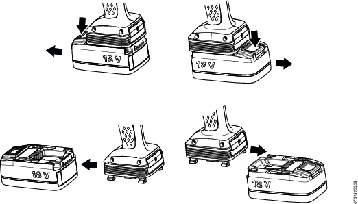
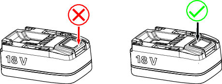
Push the button to remove the battery all the way down in order to properly remove it. Due to the shape of the Selector 6, the button can be hard to reach. Avoid pressing the button on the edge, and make sure the entire button is pushed down completely in order to fully unlock the battery, as illustrated in the image below.
Service
Selector replacement
All configuration data of a socket selector is stored in the Rapid Back Up (RBU) memory, which has the same form factor as a SD card. If a selector is broken or malfunctions, a quick replacement is as follows:
-
Unpack a new replacement unit.
-
Remove power and connections from the broken unit.
-
Remove the broken unit.
-
Open the service port cover. Use a 2 mm allen key.
-
To remove the RBU, press it inwards and then release the pressure. A spring will push it far enough out so it can be removed.
-
Remove the socket holders from the broken unit and place them in the same positions on the new unit.
-
If necessary remove mounting brackets from the broken unit and install them on the new unit.
-
Move the stickers from the broken unit to the new unit, or create new stickers.
-
Place the RBU into the card holder of the replacement unit. It can only be inserted in one correct way. Press it firmly to the bottom. A small clicking sound confirms that the spring is locked and the card is secured in the slot.
-
Close the service port cover and secure it with the screw.
-
Install the new unit and secure it in its dedicated place.
-
Reconnect all connections to their initial places and connect power to the new unit.
Detailed instructions and figures showing the installation of the selector, cables and socket holders are given in the Installation chapter.
Maintenance instructions
Service recommendations
Preventive maintenance is recommended at regular intervals. See the detailed information on preventive maintenance. If the product is not working properly, take it out of service and inspect it.
If no detailed information about preventive maintenance is included, follow these general guidelines:
-
Clean appropriate parts accurately
-
Replace any defective or worn parts
Backup Battery Maintenance
The information in this section is only applicable to the following products:
Selector 6 M4, 8433061304
Selector 6 M8, 8433061308
Selector 6 M8Bit, 8433061309
The product includes a mobility module with an internal backup battery. The backup battery is used, for example, to keep the radio communication active during exchange of the main battery. The backup battery gives approximately 30 seconds to exchange the main battery, before the product shuts down.
Storage Conditions
If the product is not being used, replace the mobility module at least every 12 months. The replacement procedure must be carried out by a qualified service technician. A replaced mobility module is to be recycled according to the Recycling Instruction.
The backup battery lifetime is negatively affected by extreme temperatures. Store the product in an environment with an ambient temperature between 0 - 30 °C.
If a newly manufactured product is to be kept in storage, make sure to power it up for at least four hours before putting it in storage.
While in storage, make sure to power on the product at least every five months to recharge the backup battery. The product must be powered on for at least four hours each time.
Selector software update
The selector software can be updated as follows:
Using a PC connected to the RJ45 connector in the service port and web interface update function.
The update process can take between 2-10 minutes.
Ensure that enough battery capacity is available when doing a software update to a battery powered selector. The battery indicator shall show at least one white steady LED bar.
Selector software upgrade from a PC
Disconnect all power from the selector.
Open the service port cover on the selector. The cover is secured by a 2 mm allen screw.
Connect an ethernet cable between a PC and the RJ-45 connector in the service interface.
Verify that the RBU is correctly inserted into the SD card slot, or insert the card.
Connect power to the selector by connecting an external power supply or by connecting a battery.
Open a web browser window in the PC.
Type the web address 169.251.1.1 and press the Enter key. The web server in the selector will respond and show the selector web interface.
Select the Settings icon
 in the left menu bar. The settings workspace shows the configuration menus.
In the Service port menu, click the Update command button.
A shortcut window opens to browse for the software update file.
Select a file with the extension *.gbs and click OK.
New software is loaded.
During software loading, the red LEDs display a progress bar of the process.
Remove the Ethernet cable.
Close the service port.
The configuration settings stored in the RBU are not affected by a software update.
Recycling
Recycling instruction
When a product has served its purpose it has to be recycled properly. Dismantle the product and recycle the components in accordance with local legislation.
Batteries shall be taken care of by your national battery recovery organization.
Recycling information
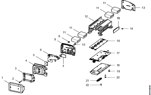
1 | Battery cover | Recycle as plastics PA6-GF25 |
2 | Screws | Recycle as steel |
3 | Battery holder | Recycle as aluminum |
4 | Side cover | Recycle as plastics PA6-GF25 |
5 | Mobility module | Recycle as electronics |
6 | Mobility module | Recycle as electronics |
7 | Back-up battery | Recycle as Li-Ion battery |
8 | Side cover | Recycle as plastics PA6-GF25 |
9 | Screws | Recycle as steel |
10 | Screws | Recycle as steel |
11 | Socket holder | Recycle as plastics PE-UHMW |
12 | Chassis | Recycle as aluminum |
13 | Side cover | Recycle as plastics PA6-GF25 |
14 | Screws | Recycle as steel |
15 | Service hatch cover | Recycle as plastics PA6-GF25 |
16 | Sensor board | Recycle as electronics |
17 | Main board | Recycle as electronics |
18 | Bottom cover | Recycle as stainless steel |
19 | Screws | Recycle as steel |
20 | Screws | Recycle as steel |
21 | Digital I/O Cover | Recycle as plastics PA6-GF25 |
22 | Screws | Recycle as steel |
Battery components (1-7) are only found in wireless models.
Licenses
This section describes the licenses used in the Selector 6 software.
ST
COPYRIGHT(c) 2014 STMicroelectronics
Redistribution and use in source and binary forms, with or without modification, are permitted provided that the following conditions are met:
Redistributions of source code must retain the above copyright notice, this list of conditions and the following disclaimer.
Redistributions in binary form must reproduce the above copyright notice, this list of conditions and the following disclaimer in the documentation and/or other materials provided with the distribution.
Neither the name of STMicroelectronics nor the names of its contributors may be used to endorse or promote products derived from this software without specific prior written permission.
THIS SOFTWARE IS PROVIDED BY THE COPYRIGHT HOLDERS AND CONTRIBUTORS "AS IS" AND ANY EXPRESS OR IMPLIED WARRANTIES, INCLUDING, BUT NOT LIMITED TO, THE IMPLIED WARRANTIES OF MERCHANTABILITY AND FITNESS FOR A PARTICULAR PURPOSE ARE DISCLAIMED. IN NO EVENT SHALL THE COPYRIGHT HOLDER OR CONTRIBUTORS BE LIABLE FOR ANY DIRECT, INDIRECT, INCIDENTAL, SPECIAL, EXEMPLARY, OR CONSEQUENTIAL DAMAGES (INCLUDING, BUT NOT LIMITED TO, PROCUREMENT OF SUBSTITUTE GOODS OR SERVICES; LOSS OF USE, DATA, OR PROFITS; OR BUSINESS INTERRUPTION) HOWEVER CAUSED AND ON ANY THEORY OF LIABILITY, WHETHER IN CONTRACT, STRICT LIABILITY, OR TORT (INCLUDING NEGLIGENCE OR OTHERWISE) ARISING IN ANY WAY OUT OF THE USE OF THIS SOFTWARE, EVEN IF ADVISED OF THE POSSIBILITY OF SUCH DAMAGE.
FatFs
FatFs license is of BSD-style but there is a significant feature, FatFs is mainly intended for embedded systems. In order to extend the usability for commercial products, the redistributions of FatFs in binary form, such as embedded code or any forms without source code, does not need acknowledgement of FatFs in the documentation.
Following code block shows a copy of the FatFs license document that included in the source files.
/*---------------------------------------------------------------------------/
/ FatFs - FAT file system module R0.11 (C)ChaN, 2015
/----------------------------------------------------------------------------/
/ FatFs module is a free software that opened under license policy of
/ following conditions.
/
/ Copyright (C) 2015, ChaN, all right reserved.
/
/ 1. Redistributions of source code must retain the above copyright notice,
/ this condition and the following disclaimer.
/
/ This software is provided by the copyright holder and contributors "AS IS"
/ and any warranties related to this software are DISCLAIMED.
/ The copyright owner or contributors be NOT LIABLE for any damages caused
/ by use of this software.
/---------------------------------------------------------------------------*/
LWIP
Copyright (c) 2001-2004 Swedish Institute of Computer Science.
All rights reserved.
Redistribution and use in source and binary forms, with or without modification, are permitted provided that the following conditions are met:
Redistributions of source code must retain the above copyright notice, his list of conditions and the following disclaimer.
Redistributions in binary form must reproduce the above copyright notice, this list of conditions and the following disclaimer in the documentation and/or other materials provided with the distribution.
The name of the author may not be used to endorse or promote products derived from this software without specific prior written permission.
THIS SOFTWARE IS PROVIDED BY THE AUTHOR "AS IS" AND ANY EXPRESS OR IMPLIED WARRANTIES, INCLUDING, BUT NOT LIMITED TO, THE IMPLIED WARRANTIES OF MERCHANTABILITY AND FITNESS FOR A PARTICULAR PURPOSE ARE DISCLAIMED. IN NO EVENT SHALL THE AUTHOR BE LIABLE FOR ANY DIRECT, INDIRECT, INCIDENTAL, SPECIAL, EXEMPLARY, OR CONSEQUENTIAL DAMAGES (INCLUDING, BUT NOT LIMITED TO, PROCUREMENT OF SUBSTITUTE GOODS OR SERVICES; LOSS OF USE, DATA, OR PROFITS; OR BUSINESS INTERRUPTION) HOWEVER CAUSED AND ON ANY THEORY OF LIABILITY, WHETHER IN CONTRACT, STRICT LIABILITY, OR TORT (INCLUDING NEGLIGENCE OR OTHERWISE) ARISING IN ANY WAY OUT OF THE USE OF THIS SOFTWARE, EVEN IF ADVISED OF THE POSSIBILITY OF SUCH DAMAGE.
This file is part of the lwIP TCP/IP stack.
Author: Adam Dunkels <adam@sics.se>
DHCP server
Copyright (c) 2010, Valhalla Wireless
All rights reserved.
Redistribution and use in source and binary forms, with or without modification, are permitted provided that the following conditions are met:
Redistributions of source code must retain the above copyright notice, this list of conditions and the following disclaimer.
Redistributions in binary form must reproduce the above copyright notice, this list of conditions and the following disclaimer in the documentation and/or other materials provided with the distribution.
Neither the name of the Valhalla Wireless nor the names of its contributors may be used to endorse or promote products derived from this software without specific prior written permission.
THIS SOFTWARE IS PROVIDED BY THE COPYRIGHT HOLDERS AND CONTRIBUTORS "AS IS" AND ANY EXPRESS OR IMPLIED WARRANTIES, INCLUDING, BUT NOT LIMITED TO, THE IMPLIED WARRANTIES OF MERCHANTABILITY AND FITNESS FOR A PARTICULAR PURPOSE ARE DISCLAIMED. IN NO EVENT SHALL Valhalla Wireless BE LIABLE FOR ANY DIRECT, INDIRECT, INCIDENTAL, SPECIAL, EXEMPLARY, OR CONSEQUENTIAL DAMAGES (INCLUDING, BUT NOT LIMITED TO, PROCUREMENT OF SUBSTITUTE GOODS OR SERVICES; LOSS OF USE, DATA, OR PROFITS; OR BUSINESS INTERRUPTION) HOWEVER CAUSED AND ON ANY THEORY OF LIABILITY, WHETHER IN CONTRACT, STRICT LIABILITY, OR TORT (INCLUDING NEGLIGENCE OR OTHERWISE) ARISING IN ANY WAY OUT OF THE USE OF THIS SOFTWARE, EVEN IF ADVISED OF THE POSSIBILITY OF SUCH DAMAGE.
History
creation t.elliott 2010
jQuery core
jQuery Foundation projects are released under the terms of the license specified in the project's repository or if not specified, under the MIT license.
The MIT License is simple and easy to understand and it places almost no restrictions on what you can do with a jQuery Foundation project.
You are free to use any jQuery Foundation project in any other project (even commercial projects) as long as the copyright header is left intact.
"Copyright jQuery Foundation and other contributors, https://jquery.org/
This software consists of voluntary contributions made by many individuals. For exact contribution history, see the revision history available at https://github.com/jquery/jquery
The following license applies to all parts of this software except as documented below:
====
Permission is hereby granted, free of charge, to any person obtaining a copy of this software and associated documentation files (the "Software"), to deal in the Software without restriction, including without limitation the rights to use, copy, modify, merge, publish, distribute, sublicense, and/or sell copies of the Software, and to permit persons to whom the Software is furnished to do so, subject to the following conditions:
The above copyright notice and this permission notice shall be included in all copies or substantial portions of the Software.
THE SOFTWARE IS PROVIDED "AS IS", WITHOUT WARRANTY OF ANY KIND, EXPRESS OR IMPLIED, INCLUDING BUT NOT LIMITED TO THE WARRANTIES OF MERCHANTABILITY, FITNESS FOR A PARTICULAR PURPOSE AND NONINFRINGEMENT. IN NO EVENT SHALL THE AUTHORS OR COPYRIGHT HOLDERS BE LIABLE FOR ANY CLAIM, DAMAGES OR OTHER LIABILITY, WHETHER IN AN ACTION OF CONTRACT, TORT OR OTHERWISE, ARISING FROM, OUT OF OR IN CONNECTION WITH THE SOFTWARE OR THE USE OR OTHER DEALINGS IN THE SOFTWARE.
====


