Socket selector description
The descriptions are applicable to all the selector versions for both wired and wireless applications.
The figures show all the key user interfaces for installation and operation of the selector. The descriptions are applicable to all versions. The wireless versions have a mobility module with a radio that also connects the battery. The wired versions
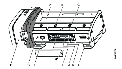
A | Space for socket holders | B | Indicator LEDs for the position |
C | Sticker area | D | Mounting holes in each corner |
E | Service port | F | Battery status LED (only available on wireless versions) |
G | WLAN status LED (only available on wireless versions) | H | Power battery (only available on wireless versions) |
I | Mobility module (only available on wireless versions) | J | Rapid Backup Unit (RBU) |
K | Function button |
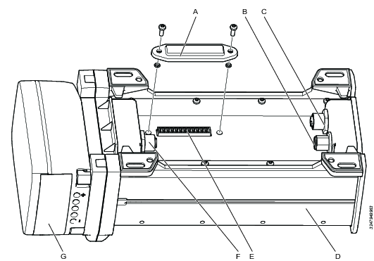
A | Connector cover | B | External DC power in; Kycon (DC DIN) connector |
C | PoE in, upstream connection; M12 D-coded female connector | D | Selector back side |
E | Digital input and output connector | F | PoE out, downstream connection; M12 D-coded female connector |
G | Battery |
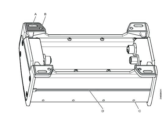
A | Holes 6 x 12 mm in each corner; accessible from above for horizontal installation | B | Threaded M4 holes in each corner; accessible from below for horizontal installation |
C | Socket holder screw | D | Groove for M4 square nut, for vertical installation |
Digital input and output connector
A connector for additional input and output signals is located under a cover at the bottom side of the selector. The digital out 1-4 are enabled when sockets 1-4 are prompted.
Currently, this functionality is only implemented on Digital Out. Digital Out is enabled when a socket position is prompted (LED blinking).
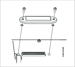
Pin number | Function |
|---|---|
1 | Digital input 1 |
2 | Digital input 2 |
3 | Digital input 3 |
4 | Digital input 4 |
5 | Common ground |
6 | Digital output 1 |
7 | Digital output 2 |
8 | Digital output 3 |
9 | Digital output 4 |
10 | Common ground |
11 | Output voltage, up to 24 V |
12 | Ground |
External digital output signals can only be supported if an external DC power supply is used. PoE and the power battery do not have enough capacity.
Indicator LEDs
The LED signals have the following functions:
Socket LEDs that guide the operator in the tightening work.
Battery status led used for portable solutions (only available on wireless versions).
Wireless connection status (only available on wireless versions).
Socket LEDs
There are two LED's for each socket or bit position. These LED's guide the operator to pick the correct socket or bit for the next tightening. The following LED lights can be shown.
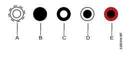
A | Outer and inner LED white and flashing | B | Both LED's switched off |
C | Inner LED steady white | D | Outer LED steady white |
E | Outer LED steady red |
More information about interpreting the LEDs is given in the Selector workflow section.
Battery status LEDs
Only available on wireless versions.
The battery status is displayed with three LEDs  when a battery is placed into the mobility module.
Three white LEDs indicates that more than 75 % battery capacity remains.
Two white LEDs indicates that less than 75% but more than 50 % battery capacity remains.
One white LED indicates that less than 50 % but more than 25 % battery capacity remains.
One red LED indicates that less than 25 % battery capacity remains and that the battery needs to be changed.
Blinking red LED indicates that the battery needs to be changed immediately.
If the battery is removed from the mobility module, these LEDs are all switched off.
Network status LED
Only available on wireless versions.
There is one single blue LED  to indicate the status of the WLAN connection:
If no wireless connection is detected, the LED is off.
If no wireless communication is established the LED is off.
If a wireless communication link is established between the selector and a network access point, the blue LED is blinking.
If communication is established between the selector and an assigned Virtual Station in the controller, the blue LED has a steady light.
If the battery is changed while the selector is assigned to a Virtual Station, the selector will retain the connection, showing a steady blue light.
Service interface
A service interface is located on the front of the socket selector. It is located beneath a cover that is fastened with a screw. The following features are available in the service interface:
One Rapid Backup Unit (RBU).
A function button.
A RJ45 connector.
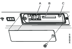
A | RJ34 Ethernet port | B | RBU slot |
C | Function button |
Function button
The function button clears all the user configurable parameters and set the to the factory default values when held down for five seconds while applying power to the selector.
RJ45 connector
This service connector is used to connect an Ethernet cable to a personal computer. The selector software contains a configuration interface (IP Address: 169.251.1.1). It is used to set up the network connection and to perform diagnostics and software loading.
Rapid Backup Unit
The RBU has the form factor of an SD card. This memory card contains all the current network configurations and settings. During the installation and configuration all the parameters are saved on the card. In case of a failure, it is a quick task to remove the card and put it into a new selector and all functionality remains the same.
This RBU card can not be used to anything else but storing the selector configuration data.


