AX1-1.5-R-B
Torque Arm
Product Information
General Information
Safety Signal Words
The safety signal words Danger, Warning, Caution, and Notice have the following meanings:
DANGER | DANGER indicates a hazardous situation which, if not avoided, will result in death or serious injury. |
WARNING | WARNING indicates a hazardous situation which, if not avoided, could result in death or serious injury. |
CAUTION | CAUTION, used with the safety alert symbol, indicates a hazardous situation which, if not avoided, could result in minor or moderate injury. |
NOTICE | NOTICE is used to address practices not related to personal injury. |
Warranty
Product warranty will expire 12+1 months after dispatch from Atlas Copco's Distribution Center.
Normal wear and tear on parts is not included within the warranty.
Normal wear and tear is that which requires a part change or other adjustment/overhaul during standard tools maintenance typical for that period (expressed in time, operation hours or otherwise).
The product warranty relies on the correct use, maintenance, and repair of the tool and its component parts.
Damage to parts that occurs as a result of inadequate maintenance or performed by parties other than Atlas Copco or their Certified Service Partners during the warranty period is not covered by the warranty.
To avoid damage or destruction of tool parts, service the tool according to the recommended maintenance schedules and follow the correct instructions.
Warranty repairs are only performed in Atlas Copco workshops or by Certified Service Partners.
Atlas Copco offers extended warranty and state of the art preventive maintenance through its ToolCover contracts. For further information contact your local Service representative.
Website
Information concerning our Products, Accessories, Spare Parts and Published Matters can be found on the Atlas Copco website.
Please visit: www.atlascopco.com.
ServAid
ServAid is a portal that is continuously updated and contains Technical Information, such as:
Regulatory and Safety Information
Technical Data
Installation, Operation and Service Instructions
Spare Parts Lists
Accessories
Dimensional Drawings
Please visit: https://servaid.atlascopco.com.
For further Technical Information, please contact your local Atlas Copco representative.
Country of Origin
For the Country of Origin, please refer to the information on the product label.
Dimensional Drawings
Dimensional Drawings can be found either in the Dimensional Drawings Archive, or on ServAid.
Please visit: http://webbox.atlascopco.com/webbox/dimdrw or https://servaid.atlascopco.com.
Overview
Product Overview
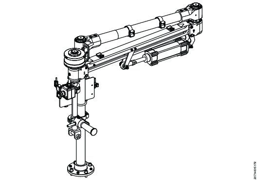
The Torque Arm is a mechanical device that holds nutrunners and screwdrivers. This articulated torque arm absorbs the reaction torque when tightening, preventing operator strain, fatigue, and injury.
This rotary torque arm with a reaction brake applies torque in both the vertical and horizontal tightening orientation. The brake adapter can swivel the vertical rod to get into correct position with the tool, and locks the rotational degree to keep the vertical rod fixed during the tightening process.
Use pistol and swiveling tool holders for the tools.
The Torque Arm is equipped with a pneumatic cylinder to provide a lift assist for the operator.

Torque Capacity | 150 Nm |
Reach Length | 1.5 m |
Payload Capacity | 7.5 kg at 4 bar |
Arm Components Overview
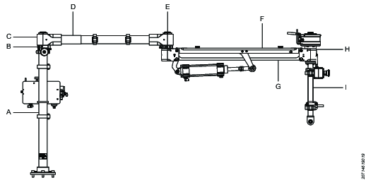
Part | Description |
|---|---|
A | Pillar |
B | Adjustable Rotation Stop |
C | Shoulder Joint |
D | Boom Arm |
E | Elbow Joint |
F | Outer Parallel Arm |
G | Inner Parallel Arm |
H | Reaction Brake |
I | Vertical Rod |
Arm Dimensions
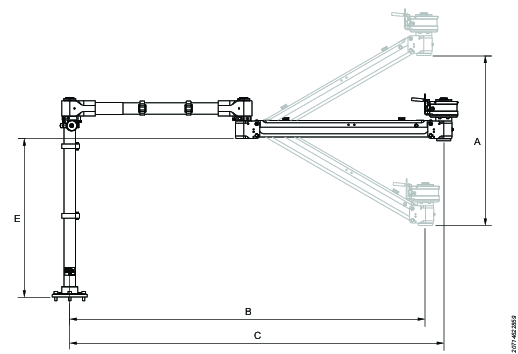
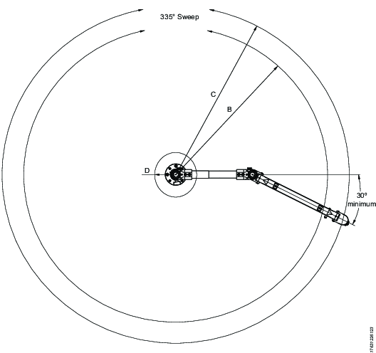
After complete setup of the torque arm, a minimum 30 degree angle limitation is important to keep.
Part | Description | Length |
|---|---|---|
A | Vertical Travel - Pneumatic | 750 mm (29.5 in) |
B | Working Radius - Pneumatic | 1460 mm (57.4 in) |
C | Max Working Radius | 1557 mm (61.2 in) |
D | Inside Working Radius | 151 mm (5.9 in) |
E | Vertical Rod Mounting Height | 686 mm (27.0 in) |
Technical Product Data
Technical Product Data can be found on either ServAid, or the Atlas Copco website.
Please visit: https://servaid.atlascopco.com or www.atlascopco.com.
Accessories
Torque Arm Accessories
Description | Accessory | Order No. |
|---|---|---|
Posi 4 | Encoder Brake Kit | 4390 2084 86 |
Workbench Mounting hardware direct (Mounting kit for arm) | WorkBench Kit Direct | 4390 1820 11 |
Workbench Mounting Hardware Through 40 mm (Mounting kit for arm) | WorkBench Kit 40 mm | 4390 1820 12 |
Workbench mounting Hardware Through 75 mm (Mounting kit for arm) | WorkBench Kit 75 mm | 4390 1820 13 |
Controller Mounting-AX1-Pillar Mount (Mounting kit for controller) | Controller Mounting Kit AX1 | 4390 1820 14 |
Vertical Rods
In Rotating Arms, a Reaction Brake allows adhered tool position for horizontal applications and vertical tightening orientations.
Use the vertical rod to connect a tool holder to the hand adapter on the articulated arm. Configure the vertical rod to get height or clearance requirements. Refer User Guide – AX1 Articulated Arm (8439 6208 90) for available fixed lengths of vertical rods.
Service Overview
Environmental Conditions
The equipment must operate in a closed and dry environment with a temperature ranging from +5° C to +50° C.
Do not use in environments where there is the possibility of an explosion (saturated with gas and/or inflammable substances).
Installation
Installation Requirements
Pneumatic System
Pneumatic Control Circuit Diagram
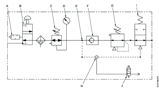
Item | Component |
|---|---|
A | Silencer |
B | Pressure relief lock-out valve (with silencer) |
C, D | Filter/regulator (with gauge) |
E | T-coupling |
F | Check valve |
G | Precision regulator |
H | Y-coupling |
I | Adjustable pilot operated locking valve |
J | 3-port solenoid valve |
Main Air Supply Adjustment
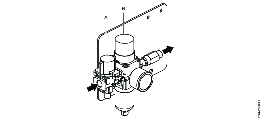
Item | Component |
|---|---|
A | Pressure relief lock-out valve |
B | Filter/Regulator with pressure gauge |
The main air supply provides air to the balance control pneumatic cylinder, and to the torque reaction brake (for models equipped with a brake). It is necessary to provide adequate minimum pressure to the system in order for the equipment to function properly and safely.
Adjust the filter/regulator unit with the knob located on the top (B).
Pull up on knob to unlock rotation.
Rotate the knob clockwise to increase pressure and counter-clockwise to decrease pressure.
Push the cap down to lock, once the pressure is set to the proper level.
Monitor the pressure level with the gauge, located on the filter/regulator.
Balance Control
The balance control works as a lift assist for easy tool positioning. To adjust the balance of the arm, configure the precision regulator (A). Pilot Operated Check Valve (B), is to prevent the parallel arm segment from falling downward in case of a sudden loss of air.
The Balance Control circuit is comprised of the following components:
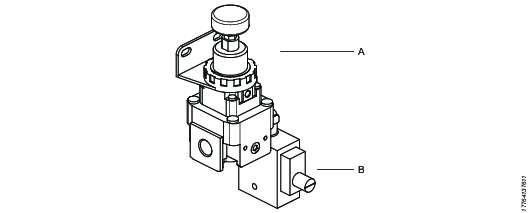
Item | Component |
|---|---|
A | Precision Regulator |
B | PO Check Valve |
Anchoring System
Item | Description | Manufacturer | Part No. | Qty. |
|---|---|---|---|---|
ETAG (Europe) | ||||
Anchor Rod - HAS-TZ M10x75/30 | Hilti | 308383 | 4 | |
Adhesive Capsule - HVU-TZ M10 | Hilti | 311368 | 4 | |
ACI (United States) | ||||
Anchor Rod - HAS-E-55 – 3/8”x3” | Hilti | 2197984 | 4 | |
Adhesive – HIT-HY 200-A | Hilti | 2022791 | 1 | |
Anchoring Overview
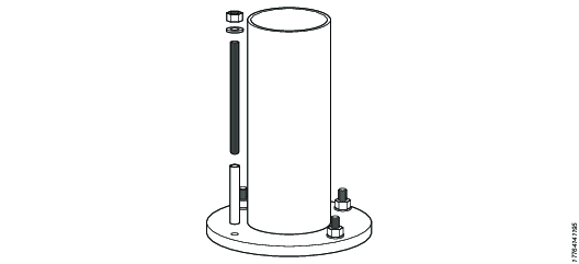
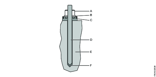
Part | Part name |
A | Locknut |
B | Washer |
C | Pedestal Base |
D | Anchor |
E | Concrete Flooring |
F | Adhesive Capsule |
Floor Properties
Torque Arms should be mounted to a surface with sufficient rigidity and support, to withstand torque reaction and total weight of Torque Arm assembly and tool.
Concrete slab thickness | 150 mm | 6 in | Minimum |
Concrete compressive strength | C20/25 | 3000 lbf/in2 | Minimum |
Aggregate size | 25 mm | 1 in | Maximum |
Reinforcing quality | 500 Bst- Ductility standard (class A) bar ASTM A615 Grade 60 bar | ||
Concrete slab area | 2.25 m2 | 3488 in2 | |
Dimensions | |||
Width | 1500 mm | 59 in | |
Length | 1500 mm | 59 in | |
Concrete steel cross sectional area | |||
Area for X- and Y- direction | 188 mm2/m | 0.089 in2/ ft | |
It is the responsibility of the end user to ensure that the floor conditions meet the indicated specifications. If a different fixing material (anchor) is chosen by the end user than what is specified, then it is their responsibility to ensure that the anchors are sufficient for the application. The appropriate installation instructions must be respected at all times.
General Installation Safety
Optimal performance is highly influenced by the initial installation. It is recommended that Atlas Copco personnel is present during installation.
Verify that all equipment sub-assemblies/parts are present. Inspect all equipment sub-assemblies/parts for damage (cracks, dents, etc) that could have occurred during handling and transportation – if damage is found, contact Atlas Copco.
It is important that the AX1 is correctly anchored to the ground. Follow the instructions to anchor and install the arm as described in the Product Instructions.
Atlas Copco technician will do the setup for:
Wiring to connect the AX-1 arm reaction brake to the PF6000 system controller.
Wiring the Emergency stop box to the PF6000 controller EM stop terminals.
The setup within ToolsTalk2 software to control the reaction brake.
Operation
Operating Instructions
Prerequisites at Start-up
All electrical components (tightening controller, power supplies, etc.) must warm up to a room temperature of 20°C in, order to avoid damage from condensation.
Ensure that the control unit for the tool is integrated properly with the power supply and the overall facility so that notices and signals can be properly dealt with.
Inspect all electrical cables, connectors, powers, pneumatic and mechanical are properly connected.
Clean and lubricate all parts of the equipment according to maintenance schedule before operating.
Inspect equipment for any damage.
Before start up, the operator of the station must be trained on the working station. Training the operator is the responsibility of the plant owner. We strongly recommend requesting Atlas Copco to perform this training with the operator.
Before Start-up
Before start-up of the equipment, the following process must be executed:
Ensure arm is positioned on parking hook.
Ensure all pneumatic components and hoses are connected properly.
Ensure controller system is powered on.
Open air supply lock-out valve to pressurize the system.
After connecting the equipment to the main air supply, verify the inlet pressure on the pressure gauge, located at the air regulator. Ensure that the pressure is set to the minimum required. If the minimum pressure is not achieved, check the main air supply.
Adjust the balance of the arm. The precision regulator can be configured by using the adjustment knob. Increase or decrease the pressure until the arm is in desired position. The force to raise and lower should be approximately the same. Ensure to tighten the lock nut, located on knob stem, after pressure adjustment.
Follow the Pilot Operated Check Valve setup procedure, to prevent the parallel arm segment from falling downward in case of a sudden loss of air.
Verify that the inductive sensor distance is 1.3 mm. (sensor is located on the brake).
Perform a functional test of the brake.
Perform a functional test of the emergency stop.
General Operation Safety
Due to entanglement risk, do not wear gloves.
Use personal protective equipment. Always wear eye protection and foot protection. Protective equipment such as steel toe-capped shoes, safety glasses and hard hat will reduce personal injuries. Always wear personal safety equipment when performing the following actions:
Equipment cleaning
Maintenance or check ups
Eliminating blocking conditions
Adjustments
The safety guards are included with the equipment and are intended to inhibit access to hazardous parts of the equipment when in operation. Any form of manipulation or modification is absolutely prohibited.
In case of input pressure reduction, position the arm on the parking hook and turn off the device until the pressure has returned.
Arm should be positioned on the parking hook at short-term interruptions.
The payload must not change during operation.
To stop the tool from functioning, turn the main switch of the tool control unit to the "OFF" position.
At the end of the work day or prior to longer inactive periods of time, position the arm on the parking hook and close the air supply shut-off valve before shut down.
Balance Control Adjustment

To balance the arm for different loading variations, the main air supply filter/regulator must first be set to the appropriate setting.
To adjust the balance of the arm, configure the precision regulator (A) with the adjustment knob.
Increase or decrease the pressure until the arm is in a level position. The force to raise and lower should be approximately the same.
Ensure to tighten the lock nut, located on knob stem, after pressure adjustment.
Ensure that air input connection thread is 1/4" G.
Air is normally released from the bleed hole (the hole on the side of the precision regulator). This is a necessary consumption of air based on the design of the regulator – it is not an abnormality.
Pilot Operated Valve Setup Procedure
A sufficient amount of air is a must to keep the parallel arm in position. Pilot Operated (PO) Check Valve prevents the pneumatic cylinder lift-assist if the air is exhausted. The function of the PO Check Valve is to prevent the parallel arm segment from falling downward in case of a sudden loss of air.
Turn on the air supply, set both the filter regulator and precision regulator pressures to properly balance the arm.
Lower the arm to the lowest position in its vertical travel or place the arm in the park position to prevent the arm from falling in case of air loss.
Decrease the main supply pressure to 0.3 bar (4 psi) less than the required balance pressure.
Ensure arm is still in balance and functional.
Increase (clockwise) the PO check adjuster to maximum spring pressure.
Verify that the PO check valve is now closed, meaning the cylinder will be locked and unable to move.
Slowly decrease (counter-clockwise) the pressure on the PO check valve until the valve opens, or until the cylinder is able to move again.
Increase the main supply pressure back to nominal specified pressure.
If performed properly, the cylinder will now remain in place if the air supply is suddenly lost.
Lock the PO check adjuster with the set screw to ensure undesired movement does not occur.
Functional Inspection of Torque Reaction Brake
Verify the sensor distance
Verify that the inductive sensor has not come loose. Distance should be set to 1.3 mm.
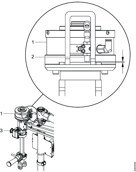
Part | Description |
|---|---|
1 | Brake |
2 | Inductive sensor |
3 | Emergency stop |
Functional test of the brake
Perform a functional test of the brake to verify that the brake closes and opens correctly when the trigger is being pushed. This could be done simply by running the tool "in the air".
It is a normally closed brake, so if the pressure is too low (for example a leaking/broken pneumatic hose) the brake will remain in a closed state. Ensure the minimum working pressure for the brake is 4 bar (~60 psi).
Emergency Stop
In case of an emergency situation:
Stop the operation by pushing the Emergency button.
Reset the emergency stop button by turning the button clockwise until it returns to its normal position.
Test the function of the emergency stop at least every 12 months.
Service
Maintenance Instructions
Maintenance Intervals
The following tables identify the maintenance intervals for AX Articulated Arm components.
Keep a maintenance log for the equipment. The maintenance log should be fixed to the equipment and include any customer-specific and other requirements if any.
Troubleshooting and repair should only be performed by skilled and trained personnel.
General
Description | Daily | Monthly | Quarterly | Annually |
Clean and wipe down the equipment using a rag or compressed air to remove dust and residue. | X | |||
Check all fasteners. | X | |||
Inspect all cables and air lines for proper routing. Ensure that all have sufficient slack at moving joints to prevent damage. | X | |||
Verify that the Inductive Sensor has not come loose. Distance should be set to 1.3 mm. | X | |||
Verify functionality of the pneumatic Torque Reaction Brake before operating the equipment. | X | |||
Inspect solenoid valves for functionality. | X | |||
Verify the brake is engaging, press the start trigger of the tool; the brake should lock. | X |
Mechanical
Description | Monthly | Quarterly | Annually |
Inspect leveling feet and anchors at pillar base. | X | ||
Inspect screws joining the shoulder joint to the pillar. | X | ||
Inspect screws at boom, elbow and parallel arm. | X | ||
Inspect screws joining hand flange and vertical rod. Vertical rod clamps to hand flange. | X | ||
Inspect screws joining the vertical rod to the tool holder. | X | ||
Verify that moving joints are properly functioning. | X | ||
Check the movement of arm for unusual drifting. Level the arm using level screws at base if necessary. | X | ||
Inspect tool for wear or damage. | X | ||
Inspect sockets for wear or damage. Replace if necessary. | X | ||
Inspect all cylinder clevis and axles for wear. Lubricate if necessary. | X | ||
Check and set all stops at shoulder and elbow joints to limit travel if necessary. Inspect clamping screws and ensure proper tightening. | X | ||
Inspect bearing operation. Remove axle shafts to inspect and manually lubricate bearings if required. | X |
Electrical
Description | Monthly | Quarterly |
Inspect cables for wear, kinks, cuts, pinches, cracks, etc. Check connectors to verify if they are loose or damaged. Replace cables if needed. | X | |
Inspect solenoid valves for functionality. | X |
Pneumatic
Description | Daily | Monthly | Quarterly | Annually |
Inspect system for air leakage. | X | |||
Inspect air preparation functionality; filter and regulator. Ensure that components do not contain debris. | X | |||
Check filter for condensation. Remove condensation if necessary. | X | |||
Replace filter element. | X | |||
Inspect air hoses and tubing for wear, kinks, cuts, pinches, cracks, etc. Check connectors to verify if they are loose or damaged. Replace hoses if needed. | X | |||
Inspect cylinder for functionality. Inspect seals for wear. Replace cylinder if necessary. | X | |||
Replace silencers. | X | |||
Check balance regulator functionality. Ensure the regulator is free of debris. | X | |||
Inspect valve functionality. Ensure the valve(s) are free of debris. | X |
General Service and Maintenance Safety
All maintenance and repair must be carried out by specialized personnel.
The balance control circuit must be serviced or repaired by specialized personnel only.
The interruption of air supply is necessary prior to any maintenance or repair. Arm should be positioned on the parking hook and the air supply shut-off vale must be closed, and the air must be exhausted from the pneumatic system.
Air hose tubing should be replaced every 6 years.
Checklist prior to maintenance or repair
Ensure the controller system is powered off.
Ensure arm is positioned on the parking hook.
Close the air supply lock-put valve to release residual pressure in the system.
PO check valve: press the manual pressure release button to release residual pressure inside the cylinder.
Verify that the pressure has been exhausted from the system by checking the gauge pressure located at the filter/regulator and after the precision regulator on the cylinder.
Storage and Packaging
Prior to storage, the equipment must be cleaned, and anti-corrosion / rust inhibitor / lubrication should be applied to parts that can oxidize. Pack the equipment within a sealed polyethylene sheet packaging.
The storage area must be a closed and dry environment with a temperature ranging from +5 °C to +50 °C.
Troubleshooting
General Troubleshooting
Symtoms | Cause(s) | Solution(s) |
|---|---|---|
Arm drifts or moves extensively. | Arm is not at level Arm payload is over capacity. | Adjust leveling of arm. Decrease payload. |
Arm is difficult to move laterally. | Bearing shoulder nut is too tight. Shoulder or elbow bearings are contaminated. Bearing require re-lubrication. | Loosen shoulder nut slightly. Check / clean / replace bearing. Re-lubricate bearings. |
Loss of air / no air supply. | Main air supply is turned off at shut-off valve. Air hose or tubing has become disconnected. Pneumatic component is blocked. Contaminated filter element: By the increased resistance of the filter the flow is limited and/or the pressure behind the filter is too low. | Check main air supply shut-off valve. Check fitting and air hose or tubing connections. Check components for blockage and clear out contaminants. Replace filter element |
Arm is difficult to raise up (high force) / easy to pull down. Arm is difficult to lower down (high force) / easy to raise up. | Load no longer balanced -incorrect setting of precision pressure regulator. | Adjust precision pressure regulator. |
Load moves suddenly after air supply is engaged. | The balance pressure for the cylinder(s) is either too low or too high. | Check setting of precision pressure regulator. |
Reaction Brake Troubleshooting
Symptoms | Cause(s) | Solution(s) |
|---|---|---|
Brake not maintaining torque - not engaging | Tooth-to-tooth gap (gap between teeth) is set too large Excessive wear on teeth | Adjust the height (distance) of tooth-to-tooth gap (gap between teeth) Replace brake assembly |
Unable to rotate the tool holder/vertical rod - brake will not disengage | Insufficient air pressure to disengage brake - air pressure too low Pneumatic/electric circuit issue Tooth-to-tooth gap (gap between teeth) is not large enough when disengaged Debris is obstructing rotation | Check compressed air supply. Increase air pressure to meet minimum supply pressure required at clutch Check circuit control valve and cabling for failure Adjust the height (distance) of tooth-to-tooth gap (gap between teeth) Clear debris from teeth |
Difficult to rotate the tool holder/vertical rod - excessive resistance when rotating | Insufficient air pressure to fully disengage brake - air pressure too low Locknut too tight Debris within bearings | Check compressed air supply. Increase air pressure to meet minimum supply pressure required Adjust resistance by loosening nut Clear debris from bearings |
Tool will not start (Brake related) | Sensor not set to proper distance from sensing block | Readjust sensor distance |
Recycling
Environmental Regulations
When a product has served its purpose it has to be recycled properly. Dismantle the product and recycle the components in accordance with local legislation.