Pneumatic System
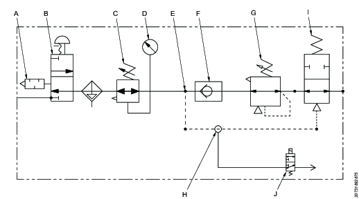
Pneumatic Control Circuit Diagram
Item | Component |
|---|---|
A | Silencer |
B | Pressure relief lock-out valve (with silencer) |
C, D | Filter/regulator (with gauge) |
E | T-coupling |
F | Check valve |
G | Precision regulator |
H | Y-coupling |
I | Adjustable pilot operated locking valve |
J | 3-port solenoid valve |
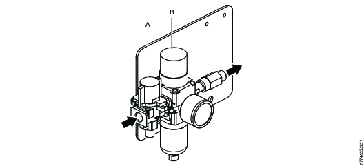
Main Air Supply Adjustment
Item | Component |
|---|---|
A | Pressure relief lock-out valve |
B | Filter/Regulator with pressure gauge |
The main air supply provides air to the balance control pneumatic cylinder, and to the torque reaction brake (for models equipped with a brake). It is necessary to provide adequate minimum pressure to the system in order for the equipment to function properly and safely.
Adjust the filter/regulator unit with the knob located on the top (B).
Pull up on knob to unlock rotation.
Rotate the knob clockwise to increase pressure and counter-clockwise to decrease pressure.
Push the cap down to lock, once the pressure is set to the proper level.
Monitor the pressure level with the gauge, located on the filter/regulator.
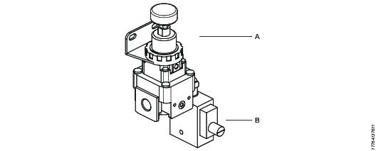
Balance Control
The balance control works as a lift assist for easy tool positioning. To adjust the balance of the arm, configure the precision regulator (A). Pilot Operated Check Valve (B), is to prevent the parallel arm segment from falling downward in case of a sudden loss of air.
The Balance Control circuit is comprised of the following components:
Item | Component |
|---|---|
A | Precision Regulator |
B | PO Check Valve |


