STRwrench Firmware (3.13)
Introduction
In this section, you can find the basic information about the product and also the formatting conventions used in the topics.
General Data Protection Regulation (GDPR)
This product offers the possibility to process personal identifiable information such as system user name, role and IP-address. The purpose of this processing capability could be to enhance quality control through traceability and proper access management.
If you decide to process personal data you need to be aware of and comply with relevant personal data protection rules, including, in the EU the GDPR as well as other applicable laws, directives and regulations. Atlas Copco can in no way be held liable for any use made by you of the product.
Liabilities and Warnings
Liability
Many events in the operating environment may affect the tightening process and shall require a validation of results. In compliance with applicable standards and/or regulations, we hereby require you to check the installed torque and rotational direction after any event that can influence the tightening result. Examples of such events include but are not limited to:
initial installation of the tooling system
change of part batch, bolt, screw batch, tool, software, configuration or environment
change of air- or electrical connections
change in line ergonomics, process, quality procedures or practices
changing of operator
any other change that influences the result of the tightening process
The check should:
Ensure that the joint conditions have not changed due to events of influence.
Be done after initial installation, maintenance or repair of the equipment.
Occur at least once per shift or at another suitable frequency.
Warnings
About the User Guide
This user guide describes how to set up and configure the STRwrench using the STRwrench user interface.
Revision History
Release Number | Revision Date | Revision Description |
|---|---|---|
3.13 | 06-2025 | NEW content:
UPDATED content:
|
3.11 | 02-2024 | NEW content:
UPDATED content:
|
3.10 | 09-2023 | NEW content:
UPDATED content:
|
3.9 | 03-2023 | NEW content:
UPDATED content:
|
3.8 | 06-2022 | NEW content:
|
3.7 | 02-2022 | NEW content:
|
3.6 | 06-2021 | NEW content:
|
1.0 | 03-2021 | First edition. |
Target group
This user guide is intended for anyone configuring or operating an STRwrench using its web user interface.
Prerequisites
Anyone interested in learning more about the STRwrench web user interface can benefit from reading this user guide.
For a complete understanding of the technical aspects in the user guide the following is recommended:
Knowledge about tightening techniques
Experience of working with Power Focus 6000 or Power Focus 4000
For more information about Power Focus 6000 and Power Focus 4000, refer to the Power Focus 6000 User Guide and the Power Focus 4000 User Guide.
Conventions
To enhance user understanding, certain formatting conventions are used throughout this document. The formatting conventions used are listed below.
Element | Notation | Description | Output |
|---|---|---|---|
General emphasis | In the Program workspace. | To make certain text elements stand out, or to highlight. | Text in Bold |
Graphical User Interface (GUI) items | Select the Function button. | Any reference to items found on screen in the GUI (for example, command buttons, icon names and field names). | Text in Bold |
Graphical User Interface (GUI) Path > | Generally, on the top of the GUI. | Navigation aid which keeps track of the location in the GUI. | For example: Controller > Program > Edit |
User input | Enter a Description for the program. | Any text input by the user. | Text in Bold |
File names | Enter a File Name for the export. | Files either exported from, or imported into the system. | Text in Bold Italic |
Variable and parameter names | Enter a Name for the export. | Variable and parameter names (not values). | Text in Italic |
Variable and parameter values | Enter a VALUE for the export. | Variable and parameter values. | Text in BOLD CAPS |
System output | Client.Domain.Models.ExportImportConfiguration | Any text output by the system. | Text in Monospace |
External links | Links to external sites that have information connected to the document or subject content. These could include:
| Selectable text to external sites | |
Internal documentation links |
If available, these links will be presented below the text. | Selectable text to internal content |
System Overview
A manufacturing system may consist of the functional blocks in the figure:
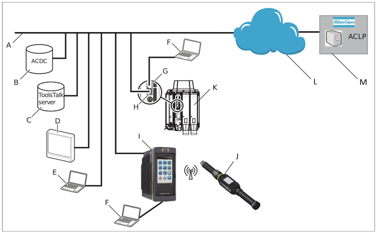
A | Factory network. | H | Controller factory port: connected to the factory network. |
B | ACDC: for storing tightening results and for statistical analysis. | I | Power Focus 6000 / Power Focus 4000 controller: used with handheld tools. |
C | ToolsTalk 2 server: for configuration and parameter settings for controllers and tools. | J | STRwrench: uses a wireless connection to the controller. |
D | Industrial PC (IPC): can be used as client terminal to the ToolsTalk 2 and ToolsNet servers. | K | PF6 Flex controller: used with fixtured tools. |
E | Portable computer connected to the factory network: can be used as client terminal to the ToolsTalk 2 and ToolsNet servers. | L | The internet cloud. |
F | Service computer: can be connected to the service port of a controller or STRwrench. | M | Atlas Copco Licensing Portal (ACLP): located at Atlas Copco and provides support to licensed functionality in the Functional Management System (FMS). |
G | Controller service port: can be used to connect a service computer. |
The User Interface
Home menu
The home menu contains the following items:
Menu Item | Description |
|---|---|
 | Tightening The Tightening menu shows a list of existing tightening programs stored in the tool. Selecting an individual program opens the different menus to configure and set parameters for the selected tightening program. |
 | Batch Sequence A batch sequence is one or more repetitive tightening programs in various combinations. Batch sequences are created and configured in the Batch sequence menu. |
 | Sources The Sources menu lists available options for controlling the selection of a tightening program, or a batch sequence, via digital input from different hardware. |
 | Configurations In this menu the following can be configured:
|
 | Integrated Controller Tool This menu includes items such as:
|
 | Reports Displays the latest events. |
 | Settings This menu is used to set up specific settings such as:
|
 | License Assignment This menu gives an overview of the current license status and license sources. |
Icons
The following table gives an overview of the icons and buttons available in the user interface:
Icon | Name | Description |
|---|---|---|
 | Back | Return to previous view. |
 | Home | Go to the Home screen. |
 | Go to Results | Go to the live results screen. |
 | Padlock | Opens a dialog box for PIN code. |
 | Events | Displays the latest tightening events. Define what events to display in the event configurations in the Settings menu. |
 | Validate | Validates tightening parameters against tool values. |
 | Add | Adds an item. |
 | Delete | Deletes an item. |
 | Protocol Status | Displays the Status Protocol pop-up window, which shows open protocol information and server connection status. |
 | Notice | Sign showing that a parameter is configured incorrectly. |
Installation and Upgrade
In this section, you can find information to help with the initial installation of the product, or upgrading from one version to another.
Installation Restrictions
Web Browser Requirements
The following web browsers are recommended for the STRwrench web user interface:
Firefox
Google Chrome
Microsoft Edge
Licenses
Feature licenses are managed through the Functionality Management System (FMS). This allows customers to tailor tool functions to their specific needs through a dynamic licensing scheme.
Licenses can be obtained for individual features or collections of features and can be deployed across multiple virtual stations. The licenses can be returned to the pool when they are no longer required.
Licenses can be downloaded from the Atlas Copco License Portal (ACLP) and managed/distributed through ToolsTalk, or can be stored on a FMS Portable (USB drive) to be inserted into the tool.
Note that the creation and management of a customer account in the ACLP is not covered in this documentation. Contact the local Atlas Copco representative for more information.
There are three types of licenses:
Virtual Station Type
A fixed collection of features bundled together in a single package. The Virtual Station Type license determines, among other things, how many programs and sequences can be used, which tightening strategies are available, and the type of reporting that can be done. The features contained in each Virtual Station Type are features that often are used in conjunction with each other, or which have internal dependencies that require the presence of other features in the package. Virtual Station Types licenses are assigned in their entirety to a virtual station. The virtual station can then make use of all features contained in the Virtual Station Type. In order to be able to perform tightenings, a Virtual Station has to be assigned a Virtual Station Type license. Depending on the license type, various tightening options will be enabled or blocked.
Virtual Station Feature
Individual features can be purchased as a single licenses to complement the virtual station type licenses.
Controller Feature
In order to perform a tightening the Integrated Controller License must be stored on the tool. (Not applicable when the Stand-alone License is assigned to the virtual station.)
There are two classes of licenses available for STRwrench Firmware:
STRwrench Integrated Controller Production license, which activates the following strategies:
Torque.
Torque (Control) / Angle (Monitor).
Torque (Monitor) / Angle (control).
Torque (Control) / Angle (Control) OR.
Torque (Control) / Angle (Control) AND.
Loose.
Yield.
STRwrench Integrated Controller Quality license, which activates the following strategies:
Residual Torque / Angle.
Residual Torque / Peak.
It is possible to install one license class as Virtual Station Type and the other one as Virtual Station feature, to activate all the strategies available for STRwrench Firmware.
License Sources
Licenses used on a tool can be pulled from several different sources. The number of simultaneous sources is limited to 10 (either 10 FMS Portable sources, or one License Server (TT2) in addition to nine FMS Portable sources). If a license is to be added from a source when the source limit (10) has been reached, all licenses from one source need to be removed from the tool to make room for licenses from the other source.
The Source Overview tab (License assignment > Source Overview) provides an overview of the licenses installed on the tool, as well as where they were installed from. A maximum number of 10 different sources can be displayed here, and each will be designated with FMS P (for FMS Portable, or dongle), or License Server (TT2).
Selecting any license source will present that source's detailed license source information. It lists the source name and type, as well as the number and type of licenses in each category (Virtual Station Type, Virtual Station Feature and Controller Feature).
Configuration of features governed by licenses can be done even in the absence of an installed license, for example, configuration of tightening programs. Assigning these features to a tool or virtual station is also possible. However, running the feature without a valid license will require the installation of the appropriate license.
License enforcement is performed at two stages: assignment and runtime (trigger pressed). If a feature for which no license is installed is assigned to a virtual station, a warning message will appear in the tool or task section of the user interface (depending on what is missing). If a feature, for which no license is installed, is started, an event will be presented informing which license is missing. It will not be possible to proceed without a correct license installed. Running an unlicensed feature will, in most cases, result in a locked tool.
Product Essentials Tutorials
https://www.youtube.com/watch?v=HanD0wI-w9k
Installing Licenses on the Tool
Note that license sources are limited to one (1) License Server (TT2) and nine FMS Portables (USB dongles) simultaneously. Licenses are either installed via the server (ToolsTalk2) or via FMS Portable. If the license source limit is reached, all licenses from one source need to be removed from the tool in order to add licenses from another source.
Existing licenses are checked against the license server every two hours. If no response from the license server is obtained within a period of 14 days, the affected licenses will be revoked. The user will also be warned when licenses are about to expire. When a license is within 7 days of expiration, the user will be presented with a warning once every two hours. If licenses are not renewed, they will expire and the affected functions will no longer be available.
Installing Licenses from the Server
Server based licenses are distributed through ToolsTalk2. For instructions on how to install server licenses, refer to ToolsTalk2 User Guide.
To enable license installation using ToolsTalk2, the correct license server settings must be configured in the tool.
Go to Settings in the home menu ans select Server connections in the left pane.
In the Atlas Copco License Manager field, set the switch to On.
Insert the correct Server port and Server host IP address (usually the same as the IP address for ToolsTalk2).
Select Apply.
Installing Licenses from FMS Portable (USB Dongle)
The Functionality Management System (FMS) uses a special FMS Portable device to transfer functionality to and from a tool. The USB flash drive contains both a general purpose memory area and a trusted storage area that is only accessible by the License Manager in a tool. The purchased feature items are downloaded from Atlas Copco to the general purpose area. The first time the FMS Portable is inserted into a tool with a License Manager, the file is detected and decoded and the feature items are transferred to the trusted storage area that is only accessible from a License Manager.
Connect the USB dongle to the tool via a USB adapter cable.

Prior to the license installation, make sure that the tool has a wireless connection set up to the factory network.
The USB License Management window will appear. The Pool column will show the total license count on the tool from all sources. The Available on FMS P column shows the licenses available on this dongle, while the From this FMS P column shows the number of licenses that have been moved to this tool from this particular FMS P.
Select the left-pointing arrow next to the license you want to install on the tool.
The number in the Available on FMS P column will decrease by 1 and the number in the From this FMS P column will increase by 1.
Removing Licenses from the Tool
Removing Licenses Installed on the Server
For instructions on removing server-installed licenses, refer to the ToolsTalk2 User Guide.
Removing FMS Portable-installed Licenses
Connect the USB dongle to the tool via a USB adapter cable.
Prior to the license removal, make sure that the tool has a wireless connection set up to the factory network.
If the USB License Manager window is not visible, go to License Assignment in the home menu.
Select the USB icon in the top right of the window. The USB License Manager dialog box appears.
Select the right-pointing arrow next to the license that is to be removed from the tool.
Licenses that are assigned to the virtual station can be removed from the tool. However, as a result the virtual station cannot be used.
Upgrading
Firmware Versions
Two firmware versions can be installed in the tool simultaneously. Installing a second version of the firmware is useful when performing upgrades on multiple tools. When production is ready for switching to the upgraded firmware, activation of the new version is done from the STRwrench Web User Interface .
Changing firmware versions does not transfer the tool configurations or tightening programs.
Software Activation
The tool can store two installed firmware versions. By using the Software activation, it is possible to choose which firmware version to use.
Make sure to keep the battery connected to the tool throughout the procedure.
Go to Integrated Controller Tool in the home menu and select Software in the left pane.
Select Current or Stored in the Software Activation window.
The tool is automatically restarted for the activation to take effect.
Update Software Version
Make sure to keep the battery connected to the tool throughout the procedure.
If the software package to be installed is not compatible with the tool hardware, the software update will be cancelled. A warning message will be shown, pointing out which parts of the hardware that caused the cancellation.
For information on the current tool hardware, go to Integrated Controller Tool > Hardware.
Go to the Integrated Controller Tool menu and select Software in the left pane.
Go to the Software Update field and select BROWSE.
Browse and choose the zip file with the applicable software and follow the instructions to finish installation.
If the controller application fails to start repeatedly the controller will boot up in rescue mode. In rescue mode a new firmware can be installed. The rescue image is distributed with the software update and can be updated if a newer rescue image exists.
Do not power off the system during rescue image update. The system will reboot when starting the update.
Product Essentials Tutorials
https://www.youtube.com/watch?v=-Vq6uKaKfcA
Rescue Mode
After three unsuccessful restarts the tool will enter Rescue Mode. In this mode it is possible to update the firmware and/or perform disk management.
Connect the tool to the USB port of the PC. Open a web browser and type in the address 169.254.1.1.
In the Rescue Mode user interface, go to the Software Update tab.
Select the file system to be updated and browse for the correct file.
Select the Update button.
Go to the Power tab and reboot the system.
Connect the tool to the USB port of the PC. Open a web browser and type in the address 169.254.1.1.
In the Rescue Mode user interface, go to the Disk Management tab.
Choose to repair file system or clean data, as appropriate.
Select the Submit button.
Go to the Power tab and reboot the system.
Configuration
In this section, you can find detailed information about how to create, modify, and verify product settings.
Configuration options
The configuration and setting up of the tool must be done as follows:
STRwrench web user interface: The tool can be directly connected to a PC via a USB cable. If the tool is connected to a wireless network and its IP address is known, it can be accessed from a computer anywhere on the network.
Controller: This is applicable to Power Focus 6000 and Power Focus 4000 controllers. A controller can be configured regardless whether it is connected to the network or not.
This user guide covers the STRwrench web user interface. For information about Power Focus 6000 and Power Focus 4000, refer to Power Focus 6000 User Guide and Power Focus 4000 User Guide.
Getting Started
To create a better overview of the system, this section provides a quick guide covering the basic steps required to get started with the STRwrench and STRwrench Web Interface . The section does not explain every feature of the system, but instead focuses on the most basic ones.
Connect the tool to a PC and access the web user interface. Set up a wireless connection between the tool and the Power Focus.
On the Power Focus, define a tightening program containing all relevant parameters of a tightening, for example target angle and target torque.
If applicable, create a batch sequence. One or several tightening programs can be added to a batch sequence which works as a series of tightening programs. A batch sequence can for example be a certain number of tightenings with a tightening program, or a sequence of different tightening programs.
Assign a tool and a task to the virtual station. The task can be either a tightening program, a batch sequence, or a specified digital input (from for example a barcode scanner).
Accessing the STRwrench Web Interface
Remove the cover of the tool's USB connection port.
Connect the tool to the USB-port of the PC.
Open a web browser and type in the address 169.254.1.1.
To access the user interface wirelessly, refer to the instructions in the section Configure a Wireless Client.
Creating a Tightening Program
Go to Tightening in the home menu.
Select the plus icon.
In the Choose Operation Mode window, select Tightening.
Open the Properties window and type in a valid Maximum Torque Limit for the specific tool. Type Enter. Close the Properties window.
Open the Steps pane on the right and drag and drop the steps to create a tightening program.
Set Monitors and Restrictions for each step as applicable and press the Enter key.
Assigning a Task to the Virtual Station
Go to Integrated Controller Tool in the home menu.
Under Virtual Station > Task select Choose task.
Choose a Tightening program from the list.
Default Ports
Function | Default Port number | Direction | Configurable | Protocol |
ToolsTalk2 | 4551 | Out | Yes | TCP |
Toolsnet8 | 4552 | Out | Yes | TCP |
AC License Manager | 7070 | Out | Yes | TCP |
Power Focus (out) | 6677 | Out | Only on PF4000 | UDP |
Power Focus (in) | 16000 | In | No | UDP |
QAInspector | 6688 | In | No | TCP |
Open Protocol | 4545 | Out | Yes | TCP |
QATcalibrator | 60000 | In | No | TCP |
Remote Logging | 514 | Out | Yes | TCP/UDP |
Working with the Tightening Tab
This section describes the multistep tightening strategy and how to create a tightening program.
Some features require licenses distributed through the Functionality Management System (FMS). Whereas configuration of features is possible without specific licenses, the assignment and use of those features will require the correct license to be installed on the tool.
Multistep Tightening Strategy
A multistep tightening is a tightening done in several steps. The number of steps and the type of the steps vary depending on the tightening to be done. A multistep tightening program is highly configurable, including monitoring functions and restrictions. A total of 3 steps can be added to a multistep program.
Restrictions are used to make sure the tightening stops if something unexpected occurs. These restrictions could, for example, test that a maximum set torque is not reached or that a part of the multistep tightening does not take too long to run. Every step can have up to four restrictions each. Each step has mandatory step restrictions and optional step restrictions. The mandatory restrictions are included when dragging a new step to the multistep program.
Monitors are used to verify that the tightening was made according to the specification. This can be, for example, angle limits or torque limits. Every step can have up to eight monitors each. Each step has mandatory step monitors and optional step monitors. The mandatory monitors are included when dragging a new step to the multistep program.
Multistep Configuration User Interface
Tightening and multistep programs that appear dimmed indicate that they are Global Programs distributed from ToolsTalk. These programs cannot be changed via the controller GUI. Global programs can only be modified through ToolsTalk. Refer to the ToolsTalk user documentation for more information.
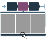
The user interface for configuring a multistep program can be divided into three main areas:
In the top there is a drop-down menu containing the Properties of the multistep tightening program. Here general properties such as program name, overall program monitor and validation can be set.
To the right there are three tabs containing the Steps, Monitors and Restrictions that can be used to build the multistep program. To use any of the items, select the appropriate tab, and drag the item in the list to the tightening area. Depending on its function, either drop the item between the beginning and the end of the program (for steps), or on top of a particular step (for monitors and restrictions).
The main area of the user interface is made up of the tightening area. This is the area that includes all the steps in the tightening program.
Adding a Multistep Program
On the Home view, select the Tightening Tab. Then, on the left, select Multistep program library.
Select the Plus icon at the upper-right corner of the GUI. Then, select the needed type of program (Tightening or Loosening).
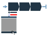
Drag and drop tightening steps, monitors and restrictions in the tightening area.
Steps can only be placed between the start and end points of the program, whilst monitors and restrictions can only be placed on steps.
Function
Description
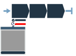
Start and end points

Start and end points of the multistep program. All steps must be placed between these two points.
Adding a step

Drag a step from the list and drop it in the desired position between the start and end points.
Moving a step

Click and hold a step and move it to the desired position
Showing step properties

Click on the step to reveal the properties
Closing step properties

Click anywhere in the tightening area to close the properties menu
Deleting a step
Open the step properties and click Delete at the bottom of the menu
Adding a restriction/monitor

Drag a restriction/monitor from the list and drop it on the appropriate step.
Moving a restriction/monitor

Click and hold the icon (checkmark for monitor, stop sign for restriction) and drag and drop it on the appropriate step
Showing restriction/monitor properties
Click on the restriction/monitor icon to reveal the properties menu
Closing restriction/monitor properties

Click anywhere in the tightening area to close the properties menu
Deleting a restriction/monitor
Open the restriction/monitor properties and click on Delete at the bottom of the menu
Step error

When a validation error occurs in a step, that step will be marked. Note that when the step properties are opened, the parameter causing the error will also be marked.
Monitor/Restriction error

When a validation error occurs in a monitor or restriction, that monitor or restriction will be marked. Note that when the monitor/restriction properties are opened, the parameter causing the error will also be marked.
Forbidden placement

When a particular placement (of a step, monitor or restriction) is not allowed, the placeholder icon will not be shown.
Deleting a Multistep Program
In the Tightening menu, click on the Multistep program library.
In the list, click on the multistep tightening program you want to delete.
In the program itself, at the bottom left, click on Delete.
Click Yes in the pop-up window to confirm your choice.
Tightening Program Properties
General Settings
Parameter | Description |
|---|---|
Name | A user-defined name for the multistep program. |
Thread Direction | Direction of the threads, either clockwise or counterclockwise |
Program Start | Sets the torque level for generating a result. If left blank, the result is generated every time the tool is started; otherwise result is only generated from the set torque level. |
Trace Configuration
The trace configuration can be done on program level or for each step. The default configuration is set on the program level and can be overridden in each step as needed.
Here, enabling this function allows the configuration to be done on program level.
Parameter | Description |
|---|---|
Enabled |
|
Sample Time | Choose the sample time from the drop-down list (1 - 1000 ms). |
With this trace recording the sample rates will not be the same in all the steps, instead the sample rate depends on the configuration in each step. This means the trace is divided into one trace for each step.
The maximum number of samples in a trace is 4096.
If a tightening produce more than 4096 values a down-sampling will take place. This is done by removing every second trace sample from the whole tightening and when continue the recording with half the resolution. This process will be repeated every time the 4096 sample limit is reached.
If more than 2048 in total was recorded, this process will result in a trace between 2048 and 4096 samples.
If the limit if 4096 samples is reached the configured trace sample times will no longer be followed. Instead the sample times will be doubled or quadrupled etc., depending on how many times the down sampling has taken place. Since all steps are down sampled the relation between the steps will still be the same though. If a step was configured with double sample time compared to another step, this will still be the case in the final trace regardless how many times a down-sampling has occurred.
If more than 4096 samples is recorded, the configured trace sample times will no longer be followed. Instead the sample times will be doubled or quadrupled, etc., depending on how many times the down sampling has taken place. Since all steps are down sampled the relation between the steps will still be the same though. If a step was configured with double sample time compared to another step, this will still be the case in the final trace regardless how many times a down-sampling has occurred.
Validation
During the configuration of tightening programs, the entered values are compared with the tool capability values to prevent parameters being outside the selected limits. User-defined maximum values are useful if many different tools are being used.
Parameter | Description |
|---|---|
Validate against tool values | On: entered values are compared with the tool capability values. Off: no validation performed. |
Tool | Shows the tool to compare the values with. |
Max Torque | Allows the user to compare the values with a simulated tool. |
Tightening Steps
The availability of tightening steps, monitors and restrictions depends on the license installed on the controller.
General Parameters
The following step parameters are common for many of the step types. The parameters are set in the step properties window which is displayed when selecting a step in the tightening program.
Parameter | Description |
|---|---|
Name | Name of the step. |
Step category | By selecting step category, the NOK tightenings will be listed in the event result view with related detailed status together with the corresponding multistep error information. |
TM - Manual Tighten to Torque
This step guides the user until the target torque is reached.
Parameter | Description |
|---|---|
Target torque | The torque target. Must be > 0. |
End Step Time | Starts when the torque goes below the Rundown complete torque after reaching the 3rd percentage. |
Ratchet time | Starts when the torque goes below the Rundown complete torque without reaching the 3rd percentage value. This allows the operator to release the torque for a while and recharge during the tightening operation. |
Torque correction coefficient | When extensions are used, the wrench measurement might be compensated to show a more accurate torque value. To calculate the correction coefficient, please refer to How to calculate the Torque Correction Coefficient. When extensions are not used, Torque correction coefficient = 1. |
Angle correction | When extensions cause additional wrench bending, the wrench angle measurement can be compensated to show a more accurate angle value. When extensions are not used, Angle correction = 0. |
AM - Manual Tighten to Angle
This step guides the user until the target angle is reached. The target angle is measured from the trigger torque.
Parameters
Parameter | Description |
|---|---|
Target angle | The angle target. Must be > 0. |
Angle search limit | If the Stop condition of the Angle monitor is set to Peak Angle, the result is taken at the maximum torque within the angle window defined here, starting backward from the angle peak measured. The maximum value is 4°. |
End cycle time | Starts when the torque goes below the Rundown complete torque after reaching the 3rd percentage. |
Ratchet time | Starts when the torque goes below the Rundown complete torque without reaching the 3rd percentage value. This allows the operator to release the torque for a while and recharge during the tightening operation. |
Torque correction coefficient | When extensions are used, the wrench measurement might be compensated to show a more accurate torque value. To calculate the correction coefficient, please refer to How to calculate the Torque Correction Coefficient. When extensions are not used, Torque correction coefficient = 1. |
Angle correction | When extensions cause additional wrench bending, the wrench angle measurement can be compensated to show a more accurate angle value. When extensions are not used, Angle correction = 0. |
AM - Manual Loosen to Angle
This step guides the user in loosening a joint until the target angle is reached. The target angle is measured from the trigger torque.
Parameters
Parameter | Description |
|---|---|
Target angle | Angle target value. If Target angle = 0, loosening stops when the torque value goes below the Program starts value. |
End cycle time | Starts when the torque goes below the Rundown complete torque after reaching the Target angle. |
Ratchet time | Starts when the torque goes below the Rundown complete torque without reaching the Target angle value. This allows the operator to release the torque for a while and recharge during the tightening operation. |
Torque correction coefficient | When extensions are used, the wrench measurement might be compensated to show a more accurate torque value. To calculate the correction coefficient, please refer to How to calculate the Torque Correction Coefficient. When extensions are not used, Torque correction coefficient = 1. |
Angle correction | When extensions cause additional wrench bending, the wrench angle measurement can be compensated to show a more accurate angle value. When extensions are not used, Angle correction = 0. |
T&AM – Manual Tighten to Torque and Angle
This step guides the user until both target torque and target angle are reached. The target torque and the target angle must be set to > 0.
Parameter | Description |
|---|---|
Target torque | Must be > 0. |
Target angle | Must be > 0. |
End cycle time | Starts when the torque goes below the Rundown complete torque after reaching the 3rd percentage. |
Ratchet time | Starts when the torque goes below the Rundown complete torque without reaching the 3rd percentage value. This allows the operator to release the torque for a while and recharge during the tightening operation. |
Torque correction coefficient | When extensions are used, the wrench measurement might be compensated to show a more accurate torque value. To calculate the correction coefficient, please refer to How to calculate the Torque Correction Coefficient. When extensions are not used, Torque correction coefficient = 1. |
Angle correction | When extensions cause additional wrench bending, the wrench angle measurement can be compensated to show a more accurate angle value. When extensions are not used, Angle correction = 0. |
T|AM – Manual Tighten to Torque or Angle
This step guides the user until either target torque or target angle are reached. The target torque and the target angle must be set to > 0.
Parameter | Description |
|---|---|
Target torque | Must be > 0. |
Target angle | Must be > 0. |
End cycle time | Starts when the torque goes below the Rundown complete torque after reaching the 3rd percentage. |
Ratchet time | Starts when the torque goes below the Rundown complete torque without reaching the 3rd percentage value. This allows the operator to release the torque for a while and recharge during the tightening operation. |
Torque correction coefficient | When extensions are used, the wrench measurement might be compensated to show a more accurate torque value. To calculate the correction coefficient, please refer to How to calculate the Torque Correction Coefficient. When extensions are not used, Torque correction coefficient = 1. |
Angle correction | When extensions cause additional wrench bending, the wrench angle measurement can be compensated to show a more accurate angle value. When extensions are not used, Angle correction = 0. |
YM - Manual Tighten to Yield
This step guides the user until the yield point of the joint is reached.
Parameter | Description |
|---|---|
Target angle | If > 0, after detecting the yield point the operation continues until the angle reaches the Target angle value. If = 0, the operation stops when the yield point is detected. |
Ratchet time | Starts when the torque goes below the Rundown complete torque without reaching the 3rd percentage value. This allows the operator to release the torque for a while and recharge during the tightening operation. Default value: 5 sec. Minimum value: 0.1. Maximum value: 30 sec |
Linear slope coefficient | Defines the joint stiffness in the linear part of the curve. It is meant as torque/angle slope and is measured in Nm/°. Default value: 0.5. Minimum value: 0.1 (also suitable for very soft joints with a ratio less than 0.1). If the selected unit of measurement is different from Nm, the Linear slope coefficient must always be converted into Nm/°. |
Torque correction coefficient | When extensions are used, the wrench measurement might be compensated to show a more accurate torque value. To calculate the correction coefficient, please refer to How to calculate the Torque Correction Coefficient. When extensions are not used, Torque correction coefficient = 1. |
Angle correction | When extensions cause additional wrench bending, the wrench angle measurement can be compensated to show a more accurate angle value. When extensions are not used, Angle correction = 0. |
RTP - Residual Torque/Peak
This step guides the user in measuring the residual torque on a joint by detecting the peak torque necessary to rotate the screw further.
Parameter | Description |
|---|---|
Target angle | If = 0, the residual torque result is the detected peak torque value, regardless of the angle value. If > 0, the residual torque result is measured at the specified Target angle value (starting from the Trigger torque) instead of taking the peak torque value. |
Trigger torque | Defines the torque value from which the angle measurement starts (usually set to 50% of the Target torque). If Trigger torque = 0, its value is automatically set to the smartHEAD Min torque value. |
Ratchet time | Starts when the torque goes below the Rundown complete torque without reaching the 3rd percentage value. This allows the operator to release the torque for a while and recharge during the tightening operation. Default value: 5 sec. Minimum value: 0.1. |
Torque correction coefficient | When extensions are used, the wrench measurement might be compensated to show a more accurate torque value. To calculate the correction coefficient, please refer to How to calculate the Torque Correction Coefficient. When extensions are not used, Torque correction coefficient = 1. |
Angle correction | When extensions cause additional wrench bending, the wrench angle measurement can be compensated to show a more accurate angle value. When extensions are not used, Angle correction = 0. |
RTA - Residual Torque/Angle
This step guides the user in measuring the residual torque on a joint by detecting the residual point on the Torque/Angle trace.
Parameter | Description |
|---|---|
Residual angle threshold | The maximum angle (measured from the Trigger torque) for the residual torque when the residual torque is lower than the breakaway point. |
Breakaway angle threshold | The maximum angle for the residual torque (measured from the Trigger torque). |
Trigger torque | Defines the torque value from which the angle measurement starts (usually set to 50% of the Target torque). If Trigger torque = 0, its value is automatically set to the smartHEAD Min torque value. |
Ratchet time | Starts when the torque goes below the Rundown complete torque without reaching the 3rd percentage value. This allows the operator to release the torque for a while and recharge during the tightening operation. Default value: 5 sec. Minimum value: 0.1. |
Torque correction coefficient | When extensions are used, the wrench measurement might be compensated to show a more accurate torque value. To calculate the correction coefficient, please refer to How to calculate the Torque Correction Coefficient. When extensions are not used, Torque correction coefficient = 1. |
Angle correction | When extensions cause additional wrench bending, the wrench angle measurement can be compensated to show a more accurate angle value. When extensions are not used, Angle correction = 0. |
Step Monitors
The availability of tightening steps, monitors and restrictions depends on the license installed on the controller.
The step monitors are used to verify that the tightening was achieved according to the specification, for example, angle limits or torque. Each step has mandatory step monitors and optional step monitors. The mandatory monitors are included when dragging a new step to the multistep program. The optional monitors are flexible and can be placed as needed in the multistep program. Every step can have up to eight monitors each.
The following monitors are automatically added to every step that is added to the multistep tightening program.
Step Monitor | Applicable steps |
|---|---|
Angle | All |
Torque | All |
A - Angle
This step monitor measures the maximum angle reached during the monitor and checks that it is between High limit and Low limit. The angle measurement starts at the start of the monitor or, if specified, at the point where the torque passes Trigger torque for the first time during the monitor.
Parameter | Description |
|---|---|
Stop condition | Two stop condition types are available: Peak angle, Angle at peak torque (default). |
Trigger torque | The angle measurement starts at this trigger. |
Low Limit | Lowest acceptable angle. |
High Limit | Highest acceptable angle. |
LD - Loosening Detection
This monitor can be used to check the torque and direction to see if a loosening is attempted. If the applied torque is above the value set for Loosening Limit in the direction opposite to the configured thread direction of the program, the result shall be reported as NOK.
T - Torque
This step monitor measures the maximum torque reached during the monitor, including any overload, and checks that it is between High limit and Low limit.
Parameter | Description |
|---|---|
Stop condition | Two stop condition types are available: Peak torque (default), Torque at peak Angle. |
Low Limit | Lowest acceptable torque. |
High Limit | Highest acceptable torque. |
PrT - Prevailing Torque
The monitor calculates the prevailing torque value in a defined angle Window Length in order to subtract the prevailing torque value from the tightening's absolute peak torque value.
The angle Window Length, in which the prevailing torque value is calculated, starts at the angle degrees set in Start Angle Distance measured in reverse direction from the snug point, which is automatically calculated by the system in real time. The angle window then spans in opposite direction for the angle degrees set in Window Length. The calculated prevailing torque value can be either the mean or the peak torque value measured during the Window Length according to the Use value set for the tightening operation. If Compensation is set to On, the calculated prevailing torque value is subtracted from the absolute peak torque value, and the torque final result value is the difference between the torque peak value and the prevailing torque value.
Parameter | Description |
|---|---|
Delay monitoring | Angle value after which the angle reading must start. |
Start Angle Distance | Angle value that, spanning in reverse direction from the snug point, defines where the angle Window Lenght starts. |
Window Length | Angle interval during which the compensate value is calculated. |
Compensation | Method to define the tightening result:
|
High Limit | Upper torque limit value to get an OK result. High Limit must be > 0 |
Low Limit | Lower torque limit value to get an OK result. Low Limit must be ≥ 0 |
Use value | Method to define how to calculate the prevailing torque value in the angle Window Length interval:
|
This step monitor can be used only with the tightening step TM - Manual Tighten to Torque.
Step Restrictions
Restrictions are predefined conditions that, when triggered, result in a tightening failure.
These restrictions help maintain process integrity by preventing invalid or excessive tightening operations.
Rh-Rehit
The Rh-Rehit validates torque within the Angle Window. If the measured torque exceeds the defined Torque Low Limit, the wrench displays a “Joint Already Tightened” error message.
Parameter | Description |
|---|---|
Angle Window | The Angle Window is measured from the beginning of the step. It must be smaller than the defined Angle Low Limit. |
Ti - Maximum time
This restriction checks the time. If the Maximum time Limit is reached, the wrench show an error.
Parameter | Description |
|---|---|
Maximum Time | If this time is exceeded, the wrench shows an error. |
Working with the Batch Sequence Tab
Batch sequences are used to perform a specified number of tightenings in a specific order.
The tightening order can either follow a fixed scheme, or be left to the operator to decide in a free-order scheme. In either case, the sockets or signals can be used to communicate between the tool and the operator.
A Batch is set up to perform a specified number of consecutive tightenings using the same tightening program. Batches must have tightening program and batch size specified in order to run.
A Batch Sequence is an ordered set of batches, when the operation requires a combination of batches/tightening programs.
A batch sequence can consist of up to 99 batches, with a batch size of up to 250 tightenings. The batches in a batch sequence are carried out in the order listed, or by using a socket selector to choose which batch to run.
A batch sequence is completed (and the tool may be locked) when either:
All tightenings have been completed with an OK or NOK result.
The Sequence Abort Timer signal terminates the task. Unperformed tightenings are reported with NOK result.
Batch Sequence Settings
The Batch Sequence menu shows the details of a single batch sequence with the following configuration items:
Name: Sequence name and index number.
Settings: Parameters for controlling the flow and order of tightenings.
Batch Configuration: Function for creating the batch sequence from individual tightening programs. A batch consists of one single tightening program that is repeated a number of times.
Parameter | Description |
|---|---|
Name | The batch sequence name consists of an index number combined with optional characters. The index position cannot be changed. A new configuration is given lowest possible available index number. The index number is important when using sources and identifier numbers to be part of the task selection process. |
Parameter | Description | Default Value |
|---|---|---|
Lock tool on Batch sequence compl. | A batch sequence is completed when the batch sequence counter is equal to the batch sequence size. On: The tool is locked and a tightening program or batch sequence must be selected to continue performing tightenings. Off: After completion, the batch sequence is ready to be repeated. | On |
Free order | No: The configured batches will be executed in the order listed, provided they have been configured to perform tightenings. If socket has been specified, the system will prompt for the socket when the batch is to be performed. Yes: The configured batches can be executed in any order. The operator must indicate to the system which batch is to be executed by using a Socket selector. A batch is regarded as complete when all joints have been completed. | No |
Increment on NOK | Makes it possible to increment the batch counter value even though the tightening is reported as NOK. For Max consecutive NOK to work (the maximum number of times a single bolt can be tightenened), Increment on NOK must be set to No. Setting this parameter to Yes, will allow the sequence to move on to the next tightening. | No |
Max consecutive NOK | Maximum consecutive not OK (NOK) tightenings are a defined maximum allowed number of NOK consecutive tightenings in a batch. If the Max consecutive NOK number is reached, the event Too many NOK tightenings (4020) is displayed. | 0 |
Decrement on OK loosening | Decrements the counter within the currently active batch. Completed batch cannot be decremented. Never: The setting is off. Counter is not decremented when loosening is performed in the active batch. Always: decrements the counter in the active batch when loosening, if the last tightening was OK. When last tightening is OK: decrements the counter when performing a loosening in the active batch, regardless of the previous tightening result. | Never |
Sequence abort timer | On: The selected batch sequence can be aborted within a specified time limit Off: The selected batch sequence cannot be aborted. | Off |
Abort time | Time in seconds. | 10 s |
Barcode Required | Yes: to start a batch sequence, a barcode must be scanned first. No: no barcode scan is required to start a batch sequence. | No |
Parameter | Description |
|---|---|
Tightening program | The tightening program to use with the batch. |
Batch size | Number of tightenings the batch will perform. Max. number of tightenings in one batch is 99. Batch size 0 will give the batch an infinite number of tightenings. |
Identifier number | When using a socket selector or an end fitting tool, this is the socket position or TAG id used to activate the batch. |
Adding a New Batch to a Batch Sequence
Go to Batch Sequence in the home menu. The workspace displays a list of batch sequences.
Select the plus icon in the top right corner.
Issue the batch sequence with a name.
Select the relevant parameters in the settings.
Select Batch Configuration > Edit.
Select a Tightening Program for the batch.
Enter the Batch Size, that is, the number of tightenings the batch will consist of.
Enter an optional Identifier Number.
The new batch sequence will be issued the first free position in the sequence list. If there are no free slots it will be placed at the bottom of the list and assigned the lowest available index number. It is not possible to change the index number to rearrange the batch tightening order.
Deleting a Batch from a Batch Sequence
Go to Batch Sequence in the home menu. The workspace displays a list of batch sequences.
Select the Batch Sequence to be deleted.
In the bottom of the workspace, select the Delete button.
When a batch is deleted from the batch sequence, the index sequence is compressed and updated, leaving no gaps. The index number of the deleted batch sequence will be assigned automatically to the next sequence that is created.
Working with the Sources Tab
External signals used as tasks for tightenings are configured in the Sources menu. Sources are accessories or similar connected to a virtual station. Two types of source tasks are available:
Source Tightening task: used to select a single tightening program.
Source Batch task: used to select a batch sequence, that is, a series of tightening programs.
Source Tightening
Source tightenings link a specific tightening program to one or two identifier numbers depending on the configuration. When the identifier number is sent to the tool (by external digital signal), and, if required, the linked end fitting tool (TAG) or socket is used, the linked program will run over and over until a different signal is sent (or end fitting tool is attached, or socket is picked up). There is no batch counting.
To link separate lists to the virtual station, a source task must be assigned to the virtual station. Go to Integrated Controller Tool > Virtual Station in the home menu and select Task > Change task.
Source Tightening Properties
Parameter | Description |
|---|---|
Name | The name issued to the source tightening. |
Selector mode | Control mode: An external source selects a tightening program by requesting an identifier number. If identifier number is linked to a corresponding socket in the socket selector, the tightening program is selected by lifting the socket. Confirm mode: The external signal is not enough to activate the tightening program. In this mode an additional identifier number for socket or end fitting tool (TAG) is linked to the tightening program and must be specified under an additional column in the list. When an identifier number is requested (by an external signal), the socket or TAG identified by the number specified in the Socket identifier column must be used to activate the corresponding tightening program. |
Max consecutive NOK per program | On: The batch will advance even if a NOK tightening is performed. Off: Set Max consecutive NOK for the tightening. The batch will only advance if a successful tightening is performed. |
Max consecutive NOK | Set the number of consecutive NOK results to be allowed. If the value is set to 0, there is no check performed for NOK tightenings. When reaching max consecutive NOK, the tool locks and the sequence execution is halted. |
Batch control | Select how the source tightening is to be executed. Internal: Configure how many times a source tightening is to be repeated. External: Configure how many times a source tightening should be executed by using Open protocol or an external protocol. Any configuration change clears the source tightening to start over from a clean and known state (the batch count in the batch will be reset to 0). Ongoing tightenings are able to finish before the changes take effect. |
Barcode Required | Yes: to start a tightening program, a barcode must be scanned first. No: no barcode scan is required to start a tightening program. |
Configuring a Source Tightening
Go to Sources in the home menu, and select Tightening in the left pane.
Select the plus icon in the top right.
Issue the source tightening with a Name and select the correct Selector mode (Control or Confirm, depending on what is required).
Max consecutive NOK can be set per source tightening or per individual program included in the source tightening. Set Max consecutive NOK per program parameter to Yes or No, depending on what is required:
To set the max consecutive NOK per source tightening, set Max consecutive NOK per program to No. Set the value in the Max consecutive NOK field.
To set the max consecutive NOK per program, set Max consecutive NOK per program to Yes. For every program in the Identifier selector configuration section, set the value in the Max NOK column.
Barcode Required can be set per source tightening or per individual program included in the source tightening.
To set the Barcode Required per source tightening, set Barcode Required to Yes. A barcode scan will be required in order to start each program in the source tightening.
To set the Barcode Required per program, set Barcode Required to Yes. Then, for each program in the Identifier selector configuration section, select No or Yes in the Barcode Required column to respectively disable or enable the barcode required feature for the individual program.
By default, only one editable identifier number will be available when creating a new source tightening. At the bottom of the screen, select the plus icon to add more.
Give every item an identifier number.
To activate the program, the identifier number linked to the tightening program must correspond to the ID sent with the external digital signal (Open protocol).
If Confirm mode is selected as Selector Mode, type an additional identifier under the Socket Identifier column for the end fitting tool (TAG) or socket to be used for the tightening program (max. value: 32).
Choose a tightening program to link to each identifier number by selecting a row and choosing from the list of tightening programs.
Source Batch
Configuring a Source Batch
Go to Sources in the home menu and select Batch Sequence in the left pane.
Select the plus icon in the top right.
Issue the source batch with a Name.
Set the Abort on new identifier to Yes if scanning a new identifier string should abort the previous scan.
Select the Identifier method (Strings for text, or Number for numerical values)
If the Identifier method is set to Strings, continue with the following steps:
Set Free order to On if the strings should be able to be scanned in any order.
Identifier strings can be made up of up to four different strings. When free order is set to Off, the strings must be scanned in a specific order for the system to recognize the string.
If required, add an identifier string by selecting the plus icon in the Identifier string configuration section.
Select the Name label for the identifier string that is to be changed. In the dialog box, the following properties can be indicated per string:
Name - the name of the string
Length - the length of the string. See Combining Identifier Strings for more information on concatenating strings.
Significant positions - the relevant positions in the string. See Significant Positions to Read in Barcode String for more information on significant positions.
Saved positions - which positions are to be logged by the system. See Saved Positions for more information about Saved positions.
The ID number (1−4) in the string properties window cannot be altered, but can only be used to navigate between the different strings.
An error may occur when Free order is set to On, and the lengths of the different strings are duplicated. The scanned sequence will then not activate a tightening program. To remedy this error, set Free order to Off, or adjust the string lengths.
Select Edit in the bottom of the Identifier String Configuration field.
In the Edit window, indicate which strings (in the String contains column) that are to be linked to which batch sequence (in the Activates column). Select the plus icon at the bottom to add more strings.
Wildcards can be used when typing the "string contains". The wildcard(s) can be used at any position in the string. No batch sequence is activated in case of an ambiguous matching result.
The wildcard is a . (period)
Significant Positions
Significant positions are used to specify which characters in the barcode string to read when putting together the string to match with your pre-defined string. The number of significant positions must match the number of characters in the pre-defined strings.
Significant Positions to Read in Barcode String
The positions in the barcode string are associated with a number between 1 and 1024. The first position of the string is 1 and the last is 1024.
The significant positions must be specified following the rules described in the table below.
Description | Significant positions | Valid configuration | Barcode string to match with pre-defined string |
|---|---|---|---|
Significant positions in order | 1,2,3,7,8 | Ok | ABCGH |
Significant positions in optional order | 7,1,2,3,8 | Ok | GABCH |
Range of numbers | 1–3,7-8 | Ok | ABCGH |
Combining Identifier Strings
The identifier string is used for matching a combination of up to four strings from a factory management system or up to four scanner inputs that need to be combined into one string.
The plus and minus buttons manage how many strings that are combined. The following parameters are available:
Parameter | Description |
|---|---|
Name | The string must be given a name. |
Length | The length of the string must be known and must be entered. This is important to be able to combine the correct string identifier. |
Significant positions | The comma-separated positions or ranges (separated by hyphen) in the combined string that are used for matching. |
Saved positions | The comma-separated positions or ranges in the strings that will be saved in the result. |
The start and end parameters in each row define the individual string positions in the combined string identifier, that is used in the next step of the matching process.
The first part in the task selection process when using an identifier string as an input, is to define which positions in the string that are to be activated:
Enter the significant positions, to define which positions in the identifier string that will be used for matching. The positions must be either comma-separated, or by range.
Saved Positions
Saved positions is a field where the user can indicate which parts of each string used in the Source Batch will be saved, and how they will be represented in the log. In this field, indicate the positions in the string that need to be saved. Positions can constitute only parts of the entire string. If the field is left empty, the entire (concatenated) string will be saved. The table below shows some examples of saved position combinations.
Saved position values are comma-separated (without spaces), and ranges are indicated using a hyphen.
Identifier string | Positions |
|---|---|
String 1: 1234567 | 1-7 |
String 2: abcdef | 8-13 |
String 3: GHIJKL | 14-19 |
String 4: 890 | 20-22 |
Saved positions | Saved results |
|---|---|
(empty) | 1234567abcdefGHIJKL890 |
1-3,9,11,15,20-22 | 123bdH890 |
8-12,1-7,19,20-21 will be changed automatically to: 1-12,19-21 | 1234567abcdeL89 |
Barcode Scan Information
When the STRwrench works with a source batch configured with Identifier Method set to Strings, the wrench's EHMI provides information on the scanned barcodes.
Every time a barcode is scanned, the following items are available on the EHMI:
Scanned string.
OK / NOK: if the scanned barcode is recognized as one of the identifier strings included in the source batch, the word OK is displayed. If it is not recognized, the word NOK is displayed.
Scans counter: if more than one identifier string is included in the batch source, a counter keeps track of the scanned barcodes over the total amount of identifier strings.
Working with the Configurations Tab
Configurations of the tool and its accessories are made in the Configurations menu.
Tool Configuration
The following section describes how different tool functions, such as LEDs and buttons, can be configured.
Tool LEDs
The tool LEDs have the following features:
The LED ring consists of a circle of radial gradient LEDs on the STRwrench handle. The LEDs behavior can be configured to provide specific output messages to the operator according to color and behavior.
A result indicator uses the LED ring to output the status of a tightening result to the operator at the end of a tightening or loosening.
Configure LEDs
Go to Configurations in the home menu and select Tool Configurations > Edit.
In the Tool LEDs category, select Edit.
Set the parameters as applicable.
Tool LEDs Progression
The behavior of the radial gradient LEDs on the LED ring can be configured to communicate the progress of the tightening operation: three radial gradient LEDs turn green in sequence when the torque or angle values that correspond to three configured thresholds are reached. The thresholds are defined in percentage, and it is possible to configure on which value they must be calculated:
For tightening strategies with torque set as control, the thresholds can be calculated either according to the Torque min value or to the Target Torque value defined for the operation.
For tightening strategies with angle set as control, the thresholds can be calculated either according to the Angle min value or to the Target angle value defined for the operation.
Parameter | Description |
|---|---|
Green LED Threshold | This parameter defines the method to calculate the three progress thresholds. Select one of the available options:
|
First threshold | Type at what percentage of the set Green LED Threshold value the first radial gradient LED must turn on. |
Second threshold | Type at what percentage of the set Green LED Threshold value the second radial gradient LED must turn on. |
Third threshold | Type at what percentage of the set Green LED Threshold value the third radial gradient LED must turn on. |
The sum of the values set for First threshold, Second threshold and Third threshold must add up to 100%.
Result Indicator
The result indicator configures how the tool LED ring behaves to indicate tightening results status and how long this indication lasts. A pre-configured pattern can be selected from a shortcut menu. This pattern can be a combination of tightening results.
Signal | Description |
|---|---|
Red:high:yellow:low |
|
Red:NOK:yellow:low |
|
Red:NOK | LED ring turns red if the tightening result is outside the lower and upper limits values range (default behavior). |
Duration
Duration decides for how long the result indication stays on after the tightening is completed.
Use the switch to select one of the two options:
Parameter | Description |
|---|---|
To next tightening | Result indication stays on until the next tightening is initiated (default behavior). |
Time | Result indication stays on for the set duration after the tightening is completed. Default value: 5.0 s; value range: 0.1 s - 60.0 s. |
General Settings
Item | Description |
|---|---|
Front LED | On: Front LED is lit when the dedicated button is pressed. Off: Front LED will always be off. |
TAG selection | On: Select the Tightening Program/Batch or Batch Sequence according to the TAG number configured in the Batch Sequence/Source Tightening/Source Batch. Off: The tool does not select the Tightening Program/Batch or Batch Sequence. |
TAG | On: Information on the TAG is displayed and can be edited in the Integrated Controller Tool > Tool menu. Off: Information on the TAG will not be displayed. |
Buzzer | On: Audio signaling device will always be on. Off: Audio signaling device will always be off. |
Keyboard source | On: It is possible to select, start and stop tightening programs and batches directly from the tool's EHMI. Off: The EHMI can only be used to navigate the available menus and to acknowledge necessary dialogs on the EHMI screen. |
Vibration | On: Vibrating device will always be on. Off: Vibrating device will always be off. |
Loose pre-tightening check | On: Accidental unscrewing of an already tightened joint is detected before the tightening starts. Off: Function deactivated. |
Smart zeroing | On: If the STRwrench detects any movement during the zero adjustment, the zeroing procedure will start over again. Off: If the STRwrench detects any movement during the zero adjustment, the zeroing procedure will not start over again. |
Gauge indicator | On: During the tightening, on the EHMI a gauge indicator gives a visual feedback on the progress of the ongoing tightening. According to the operation's settings, the gauge indicator can display torque progress, angle progress or both. Off: During the tightening, on the EHMI only the numerical values of torque and / or angle are displayed to give a feedback on the progress of the ongoing tightening. |
EHMI
The EHMI is the Embedded Human Machine Interface. It has a graphical display and five selection buttons. Its interface is a subset of the STRwrench Firmware Software web user interface, allowing users to select tightening programs, batch sequences, and to view tool hardware information and current wireless configuration.
For the operations with EHMI, refer to Product Instruction, EHMI Operations.
Configuring a Socket Selector
The Socket Selector is a socket tray with LEDs that assists the operator in selecting the correct socket for the tightening procedure, for example, a batch sequence. When using more than one tightening program, it is convenient to use a selector. When a socket is lifted, the corresponding tightening program is selected.
Several socket selectors can be connected to the virtual station.
To connect the socket selector to the virtual station, go to Integrated Controller Tool > Virtual Station > Accessories and select Choose Accessories.
To set up the socket selector, refer to the Socket Selector Product Instructions.
Go to Configurations in the home menu and select Socket selector in the left pane.
Issue the configuration with a Name.
Select Edit.
Select Add or Remove for the correct number of socket slots. Select all the slots that are to be active (indicated in blue).
Set Control to External if the socket selection is to be controlled by an external system.
Product Essentials Tutorials
https://www.youtube.com/watch?v=cmU9pYL-kL4
Configuring an I/O Expander
To set up an I/O Expander, refer to the I/O Expander Product Instructions.
Go to Configurations in the home menu and select I/O Expander in the left pane. Select Edit.
Two lists are displayed, one for Inputs and one for Outputs.
To set a channel to an input, select the required channel in the Inputs list. Choose signal type in the appearing list.
To set a channel to an output, select the required channel in the Outputs list. Choose signal type in the appearing list.
Configuring a Stacklight
The stacklight can be configured to display the I/O signals from the tool.
The stacklight can be customized as follows:
A stack of four lights. One optional light can be added to this stack. You can also customize the order and the color of lights.
Two positions, A and B, which can be customized with indicator lamps or switches.
A buzzer placed on the side of the box that has a fixed frequency of 3000 Hz. The buzzer can be configured to activate on any tightening tool signal.
Two external outputs, two external inputs and a connector for external power.
To set up the Stacklight, refer to the CAN converter Product Instructions.
Go to Configurations in the home menu and select Stacklight. Select Edit.
For each stacklight position, select lamp color, signal type and duration.
For position A-B, select the type of lamp, button or switch and select the signal type.
Configure the buzzer and external digital inputs and outputs if needed.
Working with the Integrated Controller Tool Tab
Virtual Station
A virtual station is a software abstraction of a controller. The STRwrench has an integrated controller with one connected virtual station. Various configurations can be assigned to the virtual station as needed. It is possible to select a task, assign accessory configurations, and set communication protocol parameters.
The selected task can either be running a tightening program, running a batch sequence or enabling the task using a source configured in the Sources menu. The task can be monitored and the result of the task can be presented together with any events that may have occurred during the operation.
Changing a License Type
Go to Integrated Controller Tool in the home menu and select Virtual Station in the left pane.
Select the Virtual station type in the License field.
Select a new type from the list.
If applicable, select Features>Edit, to add licenses for individual features.
Product Essentials Tutorials
https://www.youtube.com/watch?v=HanD0wI-w9k
Assigning a Task to a Virtual Station
Go to Integrated Controller Tool in the home menu and select Virtual Station in the left pane. Select Choose task or Change task in the Task menu.
Select one of the following tabs :
Tightening program: Displays a list of tightening programs available in the tool.
Batch: Displays a list of batch sequences available in the tool.
Sources: Displays a list of source tasks available in the tool.
Select a task from the list.
The task name is updated in the Task field.
The task selection using sources and identifier numbers/identifier strings, is described in detail in the Sources section.
Open Protocol
Under Protocols, in the Virtual Station menu, there is a list of available communication protocols depending on the current license in use. The Open Protocol is available for all licenses.
To gain access to functionality through Open Protocol, a unique port must be defined for the virtual station.
Go to Integrated Controller Tool in the home menu and select Virtual Station in the left pane.
Set the Open Protocol switch to On.
Enter the Server port number.
Enter the Communication timeout value in seconds, between 15 and 60.
Enter the PLC Index value.
PLC Index is used to map where in the shared memory the Open Protocol commands are to be written. The default value is 1 but it is possible to enter values 1 to 6.
Choose the action to be applied when the connection to the client is lost.
The Disconnect setting controls the action applied when a connection error occurs:
None - The tightening program continues normally.
Lock tool active high - The tool is locked after finishing the current tightening normally.
Unassign task - The tightening is aborted after finishing the ongoing task. Except for plain tightening programs or Batch sequences where the task will be removed after finishing.
Always lock tool - The tool is locked after finishing the current tightening, regardless of result.
Set Use legacy counter to Yes or No, depending on what is required.
By setting the counter to Yes, the legacy counter counts all tightenings in a sequence and outputs that number to secondary systems.
Set MID0015 Echo selected identifier number to Yes or No, depending on what is required.
By setting the counter to Yes, the controller responds the selected identifier number value in MID0015 PSET_SELECTED. Otherwise, the actual tightening program id is sent.
Select Apply.
Choosing Accessories
Go to Integrated Controller Tool in the home menu and select Virtual Station in the left pane.
Select Choose accessories in the Accessories field.
Choose the accessory to be connected: Socket Selector, Stacklight or I/O Expander.
In the Configuration column (left), select the configuration to be used with the accessory .
In the Connected Accessories column (right), select the accessory to use.
Go to Integrated Controller Tool in the home menu and select Virtual Station in the left pane.
Select Choose accessories in the Accessories field.
In the Assigned Accessories list, select the minus icon next to the accessory to be removed.
Tool
View Tool Information
Go to Integrated Controller Tool in the home menu and select Tool in the left pane.
Expand the Tool Information field to view the following information:
Information
Description
Model
Controller model denomination.
Serial number
The serial number of the controller may be needed when for the correct spare parts list or service instructions.
Product number
The product number of the controller.
TAG Information
Go to Integrated Controller Tool in the home and select Tool in the left pane.
Expand the TAG Information field. The following information is displayed:
Parameter
Description
TAG ID
TAG number.
Torque Correction Coefficient
Torque correction coefficient defined for the TAG.
Angle correction
Angle correction defined for the TAG.
Nominal torque
Torque at which the Angle correction is defined.
Maintenance
Go to Integrated Controller Tool in the home and select Tool in the left pane.
Expand the Maintenance field. The following information is displayed:
Parameter
Description
Is the transducer overloaded?
Yes - the transducer has been overloaded.
No - the transducer has not been overloaded.
Highest torque value
Highest torque output measured by the transducer.
Highest torque date
Date and time when the highest torque output was measured by the transducer.
Number of successful tightenings
Number of completed tightenings.
SmartHEAD angle correction coefficient at 12.5% of transducer capacity
Angle correction coefficient due to the wrench bending.
Angle correction coefficient for the smartHEAD. Note that this coefficient is related to the torsion of the smartHEAD itself. When a wrench extension is used, its angle correction coefficient must be calculate and added to the end fitting tool or program parameters.SmartHEAD angle correction coefficient at 25% of transducer capacity
Angle correction coefficient due to the wrench bending.
Angle correction coefficient for the smartHEAD. Note that this coefficient is related to the torsion of the smartHEAD itself. When a wrench extension is used, its angle correction coefficient must be calculate and added to the end fitting tool or program parameters.SmartHEAD angle correction coefficient at 75% of transducer capacity
Angle correction coefficient due to the wrench bending.
Angle correction coefficient for the smartHEAD. Note that this coefficient is related to the torsion of the smartHEAD itself. When a wrench extension is used, its angle correction coefficient must be calculate and added to the end fitting tool or program parameters.SmartHEAD angle correction coefficient at 100% of transducer capacity
Angle correction coefficient due to the wrench bending.
Angle correction coefficient for the smartHEAD. Note that this coefficient is related to the torsion of the smartHEAD itself. When a wrench extension is used, its angle correction coefficient must be calculate and added to the end fitting tool or program parameters.Transducer calibration date (CW)
Date of the last transducer torque calibration in clockwise direction.
Gyro calibration date (CW)
Date of the last transducer gyro calibration in clockwise direction.
Transducer calibration date (CCW)
Date of the last transducer torque calibration in counterclockwise direction.
Gyro calibration date (CCW)
Date of the last transducer gyro calibration in counterclockwise direction.
Next calibration date
Date of the next calibration expiration.
smartHEAD Information
Go to Integrated Controller Tool in the home and select Tool in the left pane.
Expand the smartHEAD Information field. The following information is displayed:
Parameter
Description
Model
smartHEAD model denomination.
Max torque
The maximum torque the smartHEAD can use for a tightening.
Serial Number
The serial number of the smartHEAD may be needed when for the correct spare parts list or service instructions.
Product Number
The product number of the smartHEAD.
IAM
The Intelligent Application Module (IAM) is a non-volatile storage that is located in the tool. The storage module contains all the tool programs, configurations and results.
Go to Integrated Controller Tool in the home menu and select IAM.
Apply a Name to the tool.
Firmware Versions
Two firmware versions can be installed in the tool simultaneously. Installing a second version of the firmware is useful when performing upgrades on multiple tools. When production is ready for switching to the upgraded firmware, activation of the new version is done from the STRwrench Web User Interface .
Changing firmware versions does not transfer the tool configurations or tightening programs.
Software Activation
The tool can store two installed firmware versions. By using the Software activation, it is possible to choose which firmware version to use.
Make sure to keep the battery connected to the tool throughout the procedure.
Go to Integrated Controller Tool in the home menu and select Software in the left pane.
Select Current or Stored in the Software Activation window.
The tool is automatically restarted for the activation to take effect.
Update Software Version
Make sure to keep the battery connected to the tool throughout the procedure.
If the software package to be installed is not compatible with the tool hardware, the software update will be cancelled. A warning message will be shown, pointing out which parts of the hardware that caused the cancellation.
For information on the current tool hardware, go to Integrated Controller Tool > Hardware.
Go to the Integrated Controller Tool menu and select Software in the left pane.
Go to the Software Update field and select BROWSE.
Browse and choose the zip file with the applicable software and follow the instructions to finish installation.
Product Essentials Tutorials
https://www.youtube.com/watch?v=-Vq6uKaKfcA
Exporting and Importing Configurations
The export and import functions are used to export events and tightening results for analysis in external programs, as well as allowing for transferring of tightening programs, batches, and tool configurations between tools.
The export function is used to:
Export tightening results and events for further processing.
Export log files for debug assistance from an Atlas Copco service engineer.
Export tool configuration that can be used to copy settings to another tool.
Go to Integrated Controller Tool in the home menu. Select Export/Import in the left pane.
Select what to export from the tool: All information or Settings and configurations.
When Settings and configurations is chosen no file with results or events will be exported into the archive. With this setting the export takes less time to perform.
Select EXPORT. A prompt to select where to save or retrieve the exported file is shown.
Go to Integrated Controller Tool in the home menu. Select Export/Import in the left pane.
Select IMPORT. When using the import function, all settings for tightening program, batch, accessories, and tool are replaced by the settings from the import file. However, settings for network, PIN, and results and events are not imported.
Select CONTINUE in the dialog box to start the import.
Exported information and File Format
The exported file is a compressed file archive containing the following files:
All information
STRwExport_<datetime>_Events.csv
ExportInfo.txt
settings/settings.bin
atlas_sys_i.zip
atlas_plc.zip
jsonConfigurations.zip
Settings and configurations
ExportInfo.txt
settings.zip
jsonConfigurations.zip
File | Description |
|---|---|
STRwExport_<datetime>_Events.csv | A semicolon-separated file containing the following information:
|
ExportInfo.txt | Information about the tool set-up and tool software. |
settings/settings.bin | A binary file containing all tightening programs and Batch settings, Accessory configurations, and tool settings such as: Language, Torque units, Date and time, and Result appearance. |
atlas_sys_i.zip | Log files from IT application. |
atlas_plc.zip | PLC configuration. |
jsonConfigurations.zip | Multistep Tightening and Loosening programs. |
Depending on the language setting in the STRwrench Software, the exported .csv file uses different characters to separate the fields. Depending on the language setting in the computer, formatting problems may occur when opening the exported .csv file. To avoid problems, always match the language used in the tool with the language of the computer.
See the following table for language formatting details of the STRwrench Software:
Language | Date/time | Field delimiter | Number format |
|---|---|---|---|
English (en_US) | MM/dd/yyyy hh:mm:ss | , | 123.456 |
Czech (cs_CZ) | dd.MM.yyyy hh:mm:ss | ; | 123,456 |
German (de_DE) | dd.MM.yyyy hh:mm:ss | ; | 123,456 |
Spanish (es_ES) | dd/MM//yyyy hh:mm:ss | ; | 123,456 |
French (fr_FR) | dd/MM/yyyy hh:mm:ss | ; | 123,456 |
Korean (ko_KR) | yyyy-MM-dd hh:mm:ss | , | 123.456 |
Italian (it_IT) | dd/MM/yyyy hh:mm:ss | ; | 123,456 |
Japanese (ja_JP) | yyyy/MM/dd hh:mm:ss | , | 123.456 |
Portugese (pt_BR) | dd/MM/yyyy hh:mm:ss | ; | 123,456 |
Russian (ru_RU) | dd.MM.yyyy hh:mm:ss | ; | 123,456 |
Swedish (sv_SE) | yyyy-MM-dd hh:mm:ss | ; | 123,456 |
Chinese (zh_CN) | yyyy/MM/dd hh:mm:ss | , | 123.456 |
Connecting to an External Controller
In order to cover applications where a physical controller is required, the STRwrench can connect to Power Focus 8, Power Focus 6000, STpad or STpalm.
Applications where this is required can be, for example:
when using field bus
when using wired station accessories (stack light, operator panel, and so on)
when using I/O
when a controller is needed as a physical hub and buffer
Go to Integrated Controller Tool in the home menu and select Integrated Controller in the left pane.
Set Integrated Controller to Off in order to connect the STRwrench to the external controller. Wait for the tool to restart.
When the Integrated Controller is disabled, the STRwrench Web User Interface shows a reduced version of the menu, consisting of three tabs: Configurations, Tool Management and Settings.
In Settings, select STRwrench Connect > Tightening Manager and select the external controller you wish to connect the STRwrench to:
Power Focus to connect the STRwrench to Power Focus 8 or Power Focus 6000.
Click either on STRwrench or on STwrench to define which Serial Number the Power Focus will associate to the connected STRwrench:
STwrench: the Power Focus associates the smartHEAD's serial number to the connected STRwrench.
STRwrench: the Power Focus associates the STRwrench controller's serial number to the connected STRwrench.
QA Inspector to connect the STRwrench to STpad or STpalm.
Select the type of connection you wish to establish between the STRwrench and the selected external controller:
Bluetooth.
Wi-Fi.
If you select a Wi-Fi connection to Power Focus, two additional parameters will be displayed:
Server Port: This parameter is not editable.
Server host: Enter the IP address of your Power Focus.
If you select a Wi-Fi connection to QA Inspector, one additional parameter will be displayed:
Server Port: This parameter is not editable.
Select Apply and wait for the STRwrench to reboot.
In the external controller, the STRwrench will now show up in the dedicated menu section.
For further configurations in the external controller, respectively refer to Power Focus 8 User Guide, Power Focus 6000 User Guide, STpad Configuration Manual or STpalm Configuration Manual.
Pairing STRwrench to an External Controller for Bluetooth Connection
In order to set a Bluetooth connection between the STRwrench and an external controller, the tool must first be paired with the external controller.
During the pairing procedure there must be no tightening program running on the STRwrench. If your STRwrench is on, before performing the pairing you can either turn it off and on again, or disconnect and reconnect the smartHEAD to the wrench, in order to make the tool perform a zero adjustment.
Pairing STRwrench to Power Focus
Before you start the pairing process:
Make sure Bluetooth is enabled both in the tool and in the controller.
Make sure there are pairing slots available.
If possible, have a clear line of sight between tool and controller.
Make sure no other tools are being paired with the controller at the same time.
On the Home view, tap on the Tool Tab. Then, tap the pairing icon in the upper right corner.

On the top of the Pairing dialog box, select STRwrench.
Turn on the STRwrench or, if already on, connect a smartHEAD to the device.
As soon as the progress bar on the wrench display starts loading, perform the pairing sequence on the STRwrench keyboard:
If the STRwrench in use has the first keyboard version, press the keys in the order shown in the image below:

If the STRwrench in use has the new keyboard version, press the keys in the order shown in the image below:

When the message Bluetooth pairing appears on the wrench display, click Bluetooth in the Power Focus Pairing window.
The pairing process will end with one of the following results:
Pairing successful - The tool has been paired to the controller using the selected channel.
Pairing unsuccessful - This can be due to any of the following reasons:
No tool detected during the pairing process. Make sure the tool is in range and in pairing mode, and then click Close and try again.
More than one tool was found during the pairing process. Make sure no other tool is in pairing mode, and then click Close and try again.
Pairing already in progress. Make sure no one else is performing the pairing process on the controller, and then click Close and try again.
Pairing failed. Click Close and try again.
For further information, refer to Power Focus 8 User Guide and Power Focus 6000 User Guide.
Pairing STRwrench to STpad
In the STpad Home page, tap Measuring devices.
On the upper-right corner of the Measuring devices page, tap Add.
In the Measuring devices type window, tap STRwrench.
After selecting STRwrench, the Connection category of the Add STRwrench page is automatically displayed.
The General category is automatically filled once the pairing process is completed.
In the Connection category, configure the following parameters:
Connection type: in the drop-down list select IRC-B.
Trace read: In the drop-down list, select one of the following option for the trace reading from the STRwrench:
Always: always read traces.
NOK only: read NOK traces only.
Never: never read traces.
Residual double result: select the check box to save the torque/angle values of both Residual point and Peak point.
If the check box is not selected, only the torque/angle values of the Residual point are saved.Residual max torque behavior: select the check box to have a Not OK result when the Residual point is within the limits and the Peak point exceeds the maximum torque.
If the check box is not selected, the result status of the test is OK when the Residual point is within the limits and the Peak point exceeds the maximum torque.
On the upper-right corner of the Add STRwrench page, tap Pair.
It is possible to save the newly added device and perform the pairing process later. To do so, tap Save in the upper-right corner of the Add STRwrench page.
Follow the instructions displayed in the Pairing instructions window:
Turn on the STRwrench or, if already on, connect a smartHEAD to the device.
As soon as the progress bar on the wrench display starts loading, perform the pairing sequence on the STRwrench keyboard:
If the STRwrench in use has the first keyboard version, press the keys in the order shown in the image below:

If the STRwrench in use has the new keyboard version, press the keys in the order shown in the image below:

When the message Bluetooth pairing appears on the wrench display, tap Pair on the STpad Pairing instructions window.
When the message Pairing completed appears on the STpad Pairing window, tap OK.
On the upper-right corner of the Add STRwrench page, tap Save.
At the end of the pairing process, the message Bluetooth pairing done appears on the STRwrench display. Press the Select key to exit the message screen.
Pairing STRwrench to STpalm
In the STpalm Toolbar, tap the Menu icon (
 ). Then, tap Measuring devices.
In the Measuring devices page, tap the Add icon (
 ).
).In the Measuring devices type window, tap STRwrench.
In the Connection category of the Add STRwrench page, configure the following parameters:
Connection type: in the drop-down list select IRC-B.
Trace read: In the drop-down list, select one of the following option for the trace reading from the STRwrench:
Always: always read traces.
NOK only: read NOK traces only.
Never: never read traces.
Residual double result: select the check box to save the torque/angle values of both Residual point and Peak point.
If the check box is not selected, only the torque/angle values of the Residual point are saved.Residual max torque behavior: select the check box to have a Not OK result when the Residual point is within the limits and the Peak point exceeds the maximum torque.
If the check box is not selected, the result status of the test is OK hen the Residual point is within the limits and the Peak point exceeds the maximum torque.
On the upper-right corner of the Add STRwrench page, tap the More icon (
 ) and then Pair.
It is possible to save the newly added device and perform the pairing process later. To do so, tap the Save icon (
 ) in the upper-right corner of the Add STRwrench.
Follow the instructions displayed in the Pairing instructions window:
Turn on the STRwrench or, if already on, connect a smartHEAD to the device.
As soon as the progress bar on the wrench display starts loading, perform the pairing sequence on the STRwrench keyboard:
If the STRwrench in use has the first keyboard version, press the keys in the order shown in the image below:

If the STRwrench in use has the latest keyboard version, press the keys in the order shown in the image below:

When the message Bluetooth pairing appears on the wrench display, tap Pair on the STpalm Pairing instructions window.
When the message Pairing completed appears on the STpalm Pairing window, tap OK.
On the upper-right corner of the Add STRwrench page, tap the Save icon (
).
At the end of the pairing process, on the STRwrench display the message Bluetooth pairing done is shown. Press the Select key to exit the message view.
Working with the Settings Tab
Network Configurations
The tool can be set up to be accessed wirelessly from a web browser on a Local Area Network (LAN), using IPv4 protocol.
Remove the cover of the tool's USB connection port.
Connect the tool to the USB-port of the PC.
Open a web browser and type in the address 169.254.1.1.
Configuring Bluetooth
Go to Settings in the home menu and select Network in the left pane.
In the Bluetooth field, select Edit.
Set Enabled to On.
Configuring Channels
Go to Settings in the home menu and select Network in the left pane.
In the Channels field, choose frequency (2.4 GHz or 5 GHz) and select Edit.
Choose to enable or disable channels.
Configuring a Wireless Client
Go to Settings in the home menu and select Network in the left pane.
Go to Wireless Client and select Edit.
Edit the General settings.
Set Enabled to On.
Set DHCP to On or Off, depending on the configuration. If set to Off, ask your local system administrator for the correct settings.
Set the IP address, Subnet mask, and Gateway.
Enter a Network name (SSID).
Edit the Security settings.
Select Mode and choose a security mode from the list.
Edit the Security settings as applicable. The available settings depend on which mode is selected.
Security settings Setting
Description
Mode
Disabled
WPA2 Personal
WPA2 Enterprise
EAP Method
PEAP
LEAP
TLS
TTLS
FAST
Security key
Set the alphanumerical password.
Identity
Set the identity of the tool.
User name
Set the user name.
Password
Set the password.
CA-cert
Select the CA certificate with the Browse button. It can be either of PEM format or Binary (DER).
Client-cert
Select the client certificate with the Browse button. It can be either of PEM format or Binary (DER).
Private key
Select the private key with the Browse button. It can be either of PEM format or Binary (DER).
Private key password
Set the password used for the private key.
Fast PAC
Set the Protected Access Credentials (PAC).
MSCHAPv2
Set MSCHAPv2 On or Off.
AES/CCMP
Set AES/CCMP On or Off.
If uncertain, set AES/CCMP and TKIP to On and ask your local system administrator for further information.
TKIP
Set TKIP On or Off.
If uncertain, set AES/CCMP and TKIP to On and ask your local system administrator for further information.
Edit the Optional Settings as applicable.
Optional settings Setting
Description
Hostname
Set a hostname for the tool.
Warn on signal strength below (dBm)
Set the signal strength at which a warning should be given.
Roaming threshold (dBm)
Set the signal threshold at which the tool shall connect (roam) to an access point with better signal.
Active scanning interval (s)
Set the time in seconds between scans when the signal strength is bad, as defined in Roaming threshold (dBm). The tool tries harder to find an access point.
Passive scanning interval (s)
Set the time in seconds between scans when the signal strength is good, as defined in Roaming threshold (dBm).
Connect to Hidden Wi-Fi Network
If the network (SSID) is hidden, set this value to On.
Select Apply.
The tool will establish a wireless connection to the network, indicated with the tool's blue connection LED indicator emitting a steady light.
To access the user interface wirelessly, type the IP address into a web browser.
Product Essentials Tutorials
https://www.youtube.com/watch?v=IAhVDKSyFgY
Configuring the Tool as a Wireless Access Point
If multiple channels have been configured previously in Wireless Client mode, enabling Wireless AP mode will update the channel list to contain only the current/default channel for the Wireless AP mode.
Go to Settings in the home menu and select Network in the left pane.
In the Wireless AP field, select Edit.
Set Enabled to On.
Enter the required information, provided by the local system administrator:
IP address
Subnet mask
Gateway
To distribute IP addresses, set DHCP Server to On and enter IP range start and IP range stop.
Enter a Network name (SSID).
In the Security field, select Mode and choose a security mode from the list. If WPA2 Personal is chosen, enter a Security key whose length should be at least 10 digits or more.
Select Apply.
Product Essentials Tutorials
https://www.youtube.com/watch?v=ZvNtiSB2BGU
Configuration of HTTPS
HTTPS is used to encrypt end-to-end traffic between web browsers and controllers. The use of HTTPS requires a certificate which is trusted by a web browser. The controller software will generate a self-signed Certificate Authority on first startup, which in turn is used to generate the initial certificate used for HTTPS. The self-signed Certificate Authority on the controller can be replaced with one that is signed by an external Certificate Authority to create a chain of trust.
By default, HTTP redirects to HTTPS in the browser. This can be configured in the controller settings under HTTPS with the Redirect HTTP to HTTPS toggle.
Configuring HTTPS
To configure HTTPS on the controller, follow these steps:
Access the web interface of the controller. A warning message will appear from the browser due to the self-signed certificate. Select Advanced and accept the risk to continue.
Navigate to Settings and select the HTTPS tab.
In HTTPS settings, select Create CA CSR.
In the pop-up window, select Create to create a certificate signing request and then select Close when the download is complete.
Sign the certificate signing request and upload the resulting CA certificate to the controller.
Select Generate server certificate, enter the Subject Alternative Names (SAN) in the specified format, and click Generate.
After the generation is complete, a pop-up window is displayed and the session will restart automatically.
Certificates
On the Certificates tab, you can manage trusted Transport Layer Security (TLS) certificates that are signed by your local Certificate Authority (CA) or an external CA to create a chain of trust.
The controller will use the TLS certificate for HTTPS to communicate securely with ToolsNet/ToolsTalk if encryption is turned on. If the ToolsNet/ToolsTalk server requires client validation, set up the certificate at the controller side and configure ToolsNet/ToolsTalk to trust the controller's certificate.
Go to Settings in the home menu and select Certificates in the left pane.
Select the Plus icon at the upper-right corner of the GUI.
Select Choose File.
Browse and choose the certificate file.
Server connections
The tool can be set up to communicate with:
ToolsTalk − used to define tightening programs and batch sequences.
ToolsNet − used to manage and analyze data collected from the operations performed by the connected tools.
Atlas Copco License Manager − used to activate and manage software licenses.
Configuring the ToolsTalk Connection
Go to Settings in the home menu and select Server Connections in the left pane.
In the ToolsTalk field, set the following parameters:
Field
Description
On/Off
Enables/Disables communication with the ToolsTalk server
Server port
ToolsTalk server port
Server host
ToolsTalk server IP address
Select Apply.
For information on how to configure ToolsTalk, refer to the ToolsTalk 2 User Guide.
Configuring the ToolsNet Connection
Go to Settings in the home menu and select Server Connections in the left pane.
In the ToolsNet field, set the following parameters:
Field
Description
On/Off
Enables/Disables communication with the ToolsNet server
Server port
ToolsNet server port
Server host
ToolsNet server IP address
Select Apply.
For information on how to configure ToolsNet, refer to the ToolsNet 8 User Guide.
Configuring the License Manager Connection
Go to Settings in the home menu and select Server Connections in the left pane.
In the Atlas Copco License Manager field, set the following parameters:
Field
Description
On/Off
Enables/Disables communication with the Atlas Copco license manager server
Server port
Atlas Copco license manager server port
Server host
Atlas Copco license manager server IP address
Select APPLY.
Configuring the Remote Logging Connection
To connect a controller to a remote logging server, configure and activate the remote logging settings on the controller.
On the home view, go to the Settings tab and select Server connections on the left pane.
On the Remote Logging window, configure the following parameters:
Field | Description |
|---|---|
On/Off | Enables/Disables communication with the remote logging server |
TCP/UDP | Selects TCP or UDP protocol |
Server host | Remote logging server IP address |
Server port | Remote logging server port |
Configure Log Levels
To configure the logs that are stored on the remote logging server:
On the home view, go to the Settings tab and select Server connections on the left pane.
On the Remote Logging window, select Configure.
On the Configure Facilities window, select the applicable checkboxes.
Category
SysLog classification
Error
Alert, Critical, Emergency, Error
Warning
Warning
Info
Informational, Notice
To restore the selection to the previous configuration, select UNDO.
Select Apply.
Preferences
Date and Time
Date and time must be set in order for events and results to get the correct time stamp for when they occurred. The time is retrieved from one of the available sources:
Manual − the date, time, and time zone are set manually.
NTP − the date and time are retrieved from an NTP (Network Time Protocol) server defined in the user interface.
Go to Settings in the home menu and select Preferences in the left pane.
In the Date and Time field, set the following parameters:
Parameter
Description
Source
Source to retrieve the time from.
NTP Server 1
IP-address of an NTP server providing date and time for the tool.
Server 1 status
OK/No Status
NTP Server 2
IP-address of an NTP server providing date and time for the tool.
Server 2 status
OK/No Status
Date
Date entered manually if the source is set to manual.
Time
Time entered manually if the source is set to manual.
Time zone
The time zone; either the location or a standard time zone such as UTC (coordinated universal time)
Select APPLY.
After setting the date, it is recommended to reboot the STRwrench.
Setting Language
The user interface is available in the following twelve languages:
English
Czech
German
Spanish
French
Korean
Italian
Japanese
Portuguese
Russian
Swedish
Chinese
Go to Settings in the home menu and select Preferences in the left pane.
In the Language field, select the language currently in use and choose a language from the list.
The language change will take effect immediately.
Setting the Torque Unit
Torque results are displayed in the chosen unit both after a tightening is performed and when stored in the results list.
Unit | Description |
|---|---|
cNm | centinewton metre |
dNm | decinewton metre |
Nm | newton metre |
kNm | kilonewton metre |
in·lbf | inch-pound force |
ft·lbf | foot-pound force |
in·ozf | inch ounce-force |
ft·ozf | foot ounce-force |
gf·cm | gram-force centimetre |
kgf·cm | kilogram-force centimetre |
kgf·m | kilogram-force metre |
Go to Settings in the home menu and select Preferences in the left pane.
In the Torque Units field, select the unit currently in use and choose a unit from the list.
The torque unit change will take effect immediately.
Configuring Events
Each event has a default setting for whether it is to be acknowledged (ACK), logged (LOG), or displayed (DISP).
Some options cannot be changed. They are greyed out.
Go to Settings in the home menu and select Events in the left pane.
Select Configure events.
Search for the event to be configured by typing the event code in the Search field and pressing Enter.
Tick or untick the boxes ACK., LOG. and DISP., as desired.
If applicable, add information about the event in the DETAILS field.
Configuration of the Extended Logging
The automatically creates logs and stores them. These logs can be configured to include extended logging using log groups.
Use Extended Logging only in special cases. Avoid using Extended Logging during normal operations, as it can significantly impact performance.
Configuring the Log Groups
The default setting for a log group is off. To change the setting of a log group to on:
On the home view, go to the Settings tab and select Extended Logging on the left pane.
On the Log Groups window, set the group to ON.
Reset Log Groups
It is possible to reset all log groups to their default settings.
On the home view, go to the Settings tab and select Extended Logging on the left pane.
On the Reset Log Groups window, select Reset.
A pop-up window appears asking if you want to reset all log groups. Select YES.
Persistent Log Groups
The log groups resets to their default setting at every reboot. To prevent resetting use persistent log groups.
On the home view, go to the Settings tab and select Extended Logging on the left pane.
On the Keep Selection after Restart window, set Persistent to ON.
Configuring the PIN Settings
Using a PIN code prevents unauthorized usage of the tool or accidental changes. Multiple users can be added to the tool, each with its own PIN. Note that PIN codes are not linked to tool configurations but are used mainly for logging reasons.
The PIN must be a four-digit number in the range 0000–9999. When PIN is enabled, and the configured inactivity time has been reached, the tool configuration cannot edited. A maximum of 10 users can be added to the tool.
When changes are made to the PIN, the user that made the changes is logged. This will be displayed in the column Changed by, and added to the change history.
When PIN is activated a PIN code is required when accessing the tool from the web user interface. Without the correct PIN being entered, the user interface will only be readable, but not editable.
Go to the Settings in the home menu and select PIN in the left pane. Select Configure.
Set the PIN code switch to On.
The PIN can only be activated when at least one user in the list is enabled. If no user is enabled, a warning will appear.
Fill out the Inactivity timeout (in seconds) to set when the tool will be locked in case of inactivity.
The default value for Inactivity timeout is 120 seconds. Note that this is a global setting, and cannot be set on a per user basis.
Go to Settings in the home menu and select PIN in the left pane. Select Configure.
Select the plus icon in the top right.
Select the Name field to edit the entry.
In the User window, enter a Name .
Enter PIN and Confirm PIN for the user. The PIN must be a four-digit number in the range 0000–9999.
The PIN in both fields (Enter PIN and Confirm PIN) must match for the changes to be applied.
Select Permissions. The list of the available configurations appears.
Select the check box at the left of the necessary configuration(s) the user can access and make changes.
After selecting the necessary configuration(s), select OK.
The User window appears.Select all selects all the available configurations at the same time.
Select Deselect all to clear the check boxes and undo the selection.The user can access and make changes only to the configuration(s) selected in the Permissions window, and browse the unselected configurations with read-only access. For the unselected configurations, no changes are allowed.
Select Apply.
In the list of users, select the check box to the left of the user name to enable the user.
When PIN is enabled, the tool locks automatically after the configured Inactivity timeout.
To disable a PIN/user, clear the check box to the left of the user name.
Go to Settings in the home menu and select PIN in the left pane. Select Configure.
In the Users field, select the check box to the left of the user name to enable the user.
When the PIN is enabled, the tool locks automatically after the configured Inactivity timeout.
To disable a PIN/user, clear the check box to the left of the user.
Note that PINs can also be enabled and disabled by selecting the user name and setting the Enabled switch to On or Off, respectively.
Go to Settings in the home menu and select PIN in the left pane. Select Configure.
In the Users field, select the red minus icon to the right of the user name.
Select the padlock icon in the top right corner.
A dialog box with a key pad appears. Enter the PIN code and select OK.
When the PIN is enabled and the screen has been unlocked, an Open Padlock icon appears in the top right corner of the user interface.
The user interface can be locked again manually, by selecting the Open Padlock icon.
Performing Factory Reset and Clearing Results
The tool can be reverted back to its original factory settings.
All settings, configurations and historical data will be deleted when the tool is reset. Only perform a factory reset when you are completely sure that this course of action is required.
Go to Settings in the home menu and select Reset in the left pane.
In the Factory Reset Controller field, select the Reset button.
A dialog box will appear warning that all data will be deleted. Select Yes.
The tool will perform a reboot to activate the new settings.
Go to Settings in the home menu and select Reset in the left pane.
In the Clear Results field, select the Clear button.
A dialog box will appear warning that all results and events will be deleted. Select Yes.
The tool will perform a reboot to clear the data.
Reports and Statistics
In this section, you can learn about available reports and statistics.
Working with the Reports Tab
Viewing Results
This section describes how to access tightening results from the tool, and how to read the information given in the different result views.
When a tightening is performed using the Integrated Controller or connecting the STRwrench to an STpad or an STpalm, the result is stored in the tool.
Live Results and Stored Results
The live result dialog box shows results from the tool on the screen as it occurs. Tightening results are also automatically stored in the tool as soon as the tightening is finished.
Each task is displayed as one result. A single tightening can show results in a table with key parameters or as a tightening graph. A batch sequence shows all the individual tightenings in the order in which they were performed.
Live Results View
The Live Results page is available only when the STRwrench is working with the Integrated Controller Tool.
In the bottom bar of the STRwrench Web User Interface, click the results icon ( ) to open the Live Results page:

Position | Description |
|---|---|
1 | Target torque. |
2 | Torque result. |
3 | Angle result. |
4 | Target angle. |
5 | Result status. |
6 | A NOK tightening will give a detailed status of the unsuccessful tightening. |
7 | VIN (Vehicle identification number) scanned by the barcode reader. |
8 | Amount of time passed between the start and the end of the tightening. |
9 | Number of completed batches in the sequence. |
10 | Batch sequence name. |
11 | Total number of batches in the sequence. |
12 | Result of each completed batch in the sequence:
|
13 | Number of completed tightenings in the batch. |
14 | Tightening program name. |
15 | Total number of tightenings in the batch. |
16 | Number of completed tightenings in the batch:
|
Click the arrows on both sides of the page to change view and display the graph of the ongoing tightening.
If you leave the Live Results page, the live results session ends and data is cleared.
Stored Results View
The tool stores the results of operations performed either using the Integrated Controller, or connecting the STRwrench to an STpad or an STpalm.
Go to Reports in the home menu and select Results in the left pane.
Select View all results. The result list will show information about:
Date: date and time of the tightening performed.
Tightening Program: Tightening Program column shows Multistep Tightening Program name, or Batch Sequence name followed by the Tightening Program name within the Batch Sequence.
Result: Torque / Angle result.
Limits: Limits column shows only when the user sets Step Monitor or Step Restriction (Step level), or Program Monitor or Program Restrictions (Multistep Program level).
Step Monitors, Step Restrictions, Program Monitors and Program Restrictions are applicable for Final Torque and Final Angle.
Details: Tightening / loosening result details.
Trace checkbox: By selecting a trace checkbox the corresponding result will be shown in the Sync Trace Result View.
Results marked with a red bar have status NOK. For descriptions of NOK results, see the NOK Result List.
Select a result in the list to enter the Trace Result View.
The Trace Result View window shows, step by step, the tightening life-cycle.
When the tightening is NOK, the Trace Result View shows which Step Monitor or Step Restriction that caused it.
On the upper-right corner of the trace graph, select the left-arrow / right-arrow to show the necessary trace graph.
The following trace graphs are available:
Torque / Time
Torque / Angle
Angle / Time
On the trace graph, it is possible to zoom in/out, move the trace, and read x-axis and y-axis values on a specific point.
On the lower-left corner of the trace graph, select "+" to zoom in , "-" to zoom out, or the "square icon" to reset the zoom level back to the default view.
On the lower part of the Trace Result View window, detailed step information is shown.
Viewing Synchronized Traces
Go to Reports in the home menu and select Results in the left pane.
Select View all results.
Select the traces to compare by marking the
 icon of the corresponding results. A selected trace icon turns blue.
Up to 10 traces can be selected.
Results without the
icon do not support synchronization.Select the
 icon in the upper right hand corner, to open the sync trace view. When selecting the
  icon all selected result traces will be unchecked.
In the Sync Trace Result View, select the preferred Sync method from the drop-down list.
Select the trace types with the arrows in the upper right hand corner.
The Sync Trace Result View is shown below:
1 | Select method to synchronize traces and display of current sync method. |
2 | Zoom methods to examine sections of the traces in more detail. Select "+" to zoom in , "-" to zoom out, or the "square icon" to reset the zoom level back to the default view. It is also possible to zoom to a specific section by holding down the right mouse button, moving the mouse over a section, and release the right mouse button. The area inside the drawn rectangle defines the area to show. |
3 | Each result is represented by one tab, showing the time when the tightening was performed. An icon on the left of each tab reflects the outcome of the tightening:
Clicking on the icon toggles between the following display settings for its trace:
|
4 | Change primary result trace. The primary result trace is used as reference and will define the values for the x-axis. Only one trace can be set as primary result. The first selected trace (the left-most tab) is by default used as reference. |
5 | Tightening details of currently selected result. |
6 | Switch between available trace types. The following trace graphs are available:
|
Sync Methods
Sync methods are different strategies to synchronize traces by a specific value.
Traces can be synchronized by, for example, peak torque (highest torque reached for each trace). This shifts all traces along the x-axis, until each curve has its peak torque value at the exact same position on the x-axis.
All subsequent results are given an offset on the x-axis according to one of the following methods:
Sync method | Description |
|---|---|
None | Default value. Selected traces are not synced. |
Peak / Torque | All traces are synchronized towards the peak value, that is, shifted along the x-axis so that the peak values are at the same position on the x-axis as the peak value of the primary result. |
Custom / Torque |
If sync method Custom is selected and none of the traces contains the configured value, an exclamation mark is shown in the custom value field. |
If a result has no trace value that matches to the sync method it cannot be synchronized and its trace will not be shown. It will instead be shown with an exclamation mark.
If none of the traces are possible to synchronize, the error message “Unable to synchronize” is shown.
Viewing Events
Events are used to notify the user of certain state changes or occurrences in the system. They are divided into three types; Information, Warnings and Errors and require different kinds of actions.
Each event occurred is stored in the event log.
Go to Reports in the home menu and select Results in the left pane.
Select View all events.
Select an event in the list to open the event dialog box.
Event Codes
Events are used to notify the user of certain state changes or occurrences in the system. They are of different types and require different kinds of actions.
Some of the procedures described can only be performed by an Atlas Copco authorized service provider.
Event Code Groups
The event codes can be divided into the following groups:
Event code | Group | Description |
|---|---|---|
1000-1999 | Controller, Tool | Controller and Tool events. |
2000-2999 | Tool | Tool events. |
3000-3999 | Controller, Drive, Channel, Configuration | Controller and Drive events, and Step sync events. |
4000-4999 | Process | Tightening process events. |
5000-5999 | Configuration | Program configuration events. |
6000-6999 | Accessory | Accessory events. |
7000-7999 | Message | Messages. |
Event Code List Description
The following table describes the information in the event code list:
Item | Description | |
|---|---|---|
Event code | The unique event number. | |
Type | Type of event:
| |
Name | A descriptive name of the event. | |
Description | A short description of the event and why it occurred. | |
Procedure | If applicable the procedure contains an instruction on how to clear the event. | |
Event Code List
Event | Description | Procedure | ||
|---|---|---|---|---|
Code | Type | Name | ||
1000 | Info | Controller started | The controller is started. | N/A |
1001 | Warning | Controller serial number updated | Generated at start-up if IT-board box serial number (controller serial number) differs from AUX-board box serial number. AUX-board is considered to be non-replaceable in field. The controller will reboot when the serial number is updated. | Replace IT-board or box. |
1010 | Info | Tool connected | A tool is connected. | N/A |
1011 | Info | Tool disconnected | A tool is disconnected. | N/A |
1012 | Info | Tool connection rejected | OpenProtocol tool rejected controller connection. | Check if another controller is connected to the tool. |
2000 | Warning | Battery low |
| Replace battery. |
2001 | Warning | Battery empty |
| Replace battery. |
2002 | Warning | Tool battery health low | Tool battery health problem is detected. | Replace battery |
2004 | Warning | Tool is not of the preferred type | Tool has been replaced by a tool with a different Tool max torque. | Change tool |
2006 | Warning | Tool backup battery health low | The backup battery in the tool has too poor performance. | The backup battery should be replaced. |
2007 | Warning | Tool backup battery missing | Tool backup battery is missing. | Insert battery |
2008 | Warning | Tool backup battery error | Tool backup battery error detected. | Replace battery |
2009 | Warning | Backup battery voltage low | The controller's backup battery is almost empty | Replace battery |
2010 | Error | Tool software version mismatch | Tool and controller software versions not compatible. | Service tool - update tool software. |
2012 | Warning | Tool communication disturbance | Communication between tool and controller interrupted. | Relocate antenna placement. |
2013 | Warning | Illegal ring position | Tool direction switch in faulty position. | If occurring frequently - service tool. |
2014 | Warning | Tool overheated | Tool overheated. | Allow tool to cool down. |
2015 | Error | Tool temperature sensor error |
| Service tool. |
2016 | Warning | Tool pulse unit overheated | Tool pulse unit overheated. Tool is not locked, but the warning is displayed whenever the tool is started as long as the pulse unit temperature is over threshold. | Allow tool to cool down |
2019 | Warning | Tool could not start motor | Tool motor failure. | |
2020 | Warning | Tool requires motor tuning | Tool requires motor tuning. | Perform a motor tuning. |
2021 | Warning | Motor tuning failed | Motor tuning failed. | Complete motor tuning or service the tool. |
2022 | Info | Motor tuning completed | Motor tuning completed. | N/A |
2023 | Warning | The tool requires open end tuning | The tool requires open end tuning. | Perform open end tuning. |
2024 | Warning | Open end tuning failed | Open end tuning failed. | Try to perform open end tuning one more time. If it fails again, service the tool. |
2025 | Info | Open end tuning successful | Open end tuning successful. | N/A |
2026 | Warning | Open end position failed | Open end position failed. | Press the trigger again and wait for the positioning to be completed. If it fails again, service the tool. |
2027 | Warning | Usage limited due to high tool temperature | Temperature limit has been reached. Tightening has been inhibited to reduce risk for tool shutting down due to overheating. | Wait until tool temperature has been reduced. |
2030 | Error | Tool memory failure, change tool | Tool memory corrupt. | Service the tool. |
2031 | Error | Tool accessory memory corrupt | Tool accessory memory corrupt. | Service the tool accessory. |
2040 | Error | System check failure |
| |
2041 | Error | Torque transducer error | Will be generated either on calibration error or if tool reports transducer error. | Service the tool. |
2042 | Error | Angle transducer error |
| Service the tool. |
2043 | Error | Tool ground fault error |
| Service the tool. |
2044 | Info | Tool service interval expired | Indicates that servicing of the tool is needed. Triggered when the number of set tightenings has been exceeded. | Perform service of tool. |
2045 | Warning | Tool calibration data invalid | If validation of calibration data fails. | Service tool. |
2046 | Info | Tool, next calibration date has passed | Indicates that calibration of tool is needed. Triggered when calibration alarm is enabled in settings and the current time is greater than next calibration date. | Service tool. |
2047 | Info | Auto update of servicedata checksum | Indicates that service data checksum has been updated automatically. | N/A |
2048 | Info | Tool calibration value updated by QA device | Tool calibration was updated when a calibration with a QA device was performed | |
2050 | Error | Tool parameter file not supported | Required tool parameters are missing. | Update tool parameters. |
2060 | Info | Unexpected trigger behavior | Used to prevent start of tool if accessory is connected. | N/A |
2071 | Error | Tool memory corrupt | Tool descriptor is corrupt. | Service the tool. |
2072 | Info | Unknown device connected |
| |
2073 | Warning | Tool trigger supervision failure | HW channel failure. Mismatch between hardware and software of tool trigger. | |
2074 | Warning | Tool indicator board failure | Tool indicator board failure. | Service the tool. |
2075 | Warning | Tool fan voltage failure | Tool fan voltage failure. | Service the tool. |
2076 | Warning | Tool accessory bus voltage failure | Tool accessory bus voltage failure. | Service the tool. |
2077 | Warning | Tool trigger sensor error | Tool trigger sensor error. | Service the tool. |
2078 | Info | Tool Tightening program updated | Tool locked due to tightening program update. | |
2079 | Error | Tool cable not supported | Tool cable is corrupt. The chip in the cable is not responding or is damaged. | Switch cable. |
2080 | Error | Tool battery failure | DC voltage too high or too low. Battery failure. | Contact the Atlas Copco service representative and send back battery to Atlas Copco (do not reuse it!). |
2081 | Error | Tool current limit reached | The current limit has been reached and the drive is disabled. | Service the tool. |
2082 | Error | Tool current measurement error | Current measurement error. Current cannot be measured with a reliable result. | Service the tool. |
2083 | Error | Tool internal error | Various internal hardware errors. | Service the tool. |
2084 | Error | Tool internal software error | Various internal software errors. | Service the tool. |
2085 | Error | Tool RBU error | An RBU error was detected by the tool software. | Check that the RBU is correctly installed. If error is still present then service the tool. |
2086 | Error | Tool stall | Tool motor is stalling. | Service the tool. |
2087 | Warning | Tool motor current high | Tool motor current limit is exceeded, and the tool is locked. Tool will enter failsafe mode. | |
2088 | Warning | Tool battery current high | Tool battery current is too high. | |
2089 | Warning | Tool drive voltage low | Tool drive voltage is below the monitored lower voltage limit. | |
2090 | Warning | Tool drive voltage high | Tool drive voltage is above monitored higher voltage limit. | |
2091 | Warning | Tool main board error | Tool main board internal error. | |
2092 | Warning | Tool power module error | Tool power module internal error | |
2093 | Warning | Pulse unit oil level low | The oil level of the connected pulse tool is low. | Service the tool |
2094 | Warning | Pulse unit oil level empty | The oil level of the connected pulse tool is below required operational level | Service the tool |
2095 | Warning | Tool battery communication lost | Tool lost communication with battery. | Make sure battery is seated correctly. Otherwise change battery |
2096 | Error | Tool battery software version mismatch | Tool battery software incompatible with tool software. | Update software. |
2100 | Info | STwrench smartHead removed | STwrench smartHead has been removed. | Reconnect smartHead and restart the wrench. |
2101 | Warning | Wrench tightening when locked | A wrench tightening was performed when the tool status was locked in the controller. | Wait until the tool status in controller is unlocked. |
3000 | Error | Controller internal software error | Software error in the controller. | Contact service. |
3001 | Error | Controller clock battery empty | Internal battery is getting close to end of life. | Replace battery |
3010 | Warning | System overheated | The controller is overheated. | Cool down. |
3011 | Warning | Drive overheated Controller hardware | Cool down. | |
3013 | Warning | Usage limited due to high controller temperature | Temperature limit has been reached. Tightening has been inhibited to reduce risk for controller shutting down due to overheating. | Wait until controller temperature has been reduced. |
3020 | Warning | Controller hardware failure | ||
3021 | Warning | System voltage problem | DC voltage too high or too low. | N/A |
3030 | Error | IP address conflicting with another node on the network | The set IP address is in use by another device on the same network. | Change IP address on one of the devices. |
3031 | Info | Network cable unplugged | The carrier of the factory port is lost (cable disconnected). | Check the cable connection. |
3032 | Info | Pairing started | Tool pairing started. | N/A |
3033 | Info | Pairing successful | Tool pairing successful. | N/A |
3034 | Error | Pairing unsuccessful: no tool found | The controller found no tool to pair with when scanning for radio peers. | Set the tool in pairing mode and try again. |
3035 | Error | Pairing unsuccessful: more than one tool found | The controller found more than one tool when scanning for radio peers. | Ensure that only one tool is in pairing mode when starting the pairing mode on the controller. |
3036 | Error | Pairing unsuccessful: Communication error | The controller experienced a loss of connection, an unexpected answer or timeout during the pairing process. | Try to perform pairing one more time. If it fails again, service the tool. |
3037 | Info | Pairing unsuccessful: Tool slot is full | Clear one tool slot | |
3040 | Warning | Emergency stop | Drive disabled due to emergency stop. | Reset emergency stop. |
3050 | Info | System clock updated | System clock has been updated. | N/A |
3051 | Error | System clock error | Wrong time read from hardware Real Time Clock (RTC). | Change RTC battery. |
3052 | Warning | Remote start configuration error | Mismatch between HW and SW remote start configuration. | Check and verify that HW dip switch matches the selected start source. |
3053 | Info | Drive connected | StepSync drive has been connected. | |
3054 | Info | Drive disconnected | StepSync drive disconnected. | |
3055 | Warning | Mode configuration error | Generated when selected mode is configured wrongly. E.g. configuring two bolts with the same bolt number or the same channel, incomplete mode configuration | Check Toolstalk2 for mode configuration error |
3056 | Warning | Unable to start, tool or drive is missing | Generated when a used channel is missing a drive or tool. | Check Channel Menu on the HMI. Connect missing drive or tool. |
3057 | Info | Unable to start, channel is already in use | Generated when a needed channel has been allocated to another virtual station | |
3058 | info | No mode selected | Select mode | |
3059 | Warning | Failed to connect to Atlas Copco License Manager | Indicates that the controller failed to connect to the local license manager to get licenses. | Check local network. If it fails again, service the controller. |
3084 | Error | Soft PLC runtime error | eCLR has terminated in an uncontrolled way. | |
3150 | Error | Software IAM incompatibility | IAM is incompatible with the software installed on the controller. | Replace IAM. |
3160 | Error | Failed to activate newly installed software | Something went wrong during the activation. When the newly installed software starts, a fallback to the previous working software happens. This happens when the new software fails to start for three times and only during software installation. | Take an export and contact Atlas Copco for further assistance. Note down the software version you are trying to install as well as the software version that is working. |
3161 | Error | Started on unexpected software partition | The controller has started on the inactive software side and not on the expected software side. | Note down the software information (on the Home page of the controller, select Controller > Software). Try to restart the controller and make sure its running on correct software when started again. If error persists, do an export and contact Atlas Copco. |
3500 | Error | Generic license manager error | Inconsistency detected in the feature management system used. | Contact Atlas Copco representative. |
3501 | Error | License Manager Synchronization Error |
| |
3502 | Info | License Manager Synchronization Done |
| |
3503 | Warning | License manager: another source in use | License is used by another source. | Check license assignment |
3504 | Warning | License manager restart needed | Restart license manager | |
3505 | Info | USB license synchronization started | ||
3506 | Error | USB license synchronization error | ||
3507 | Info | USB license synchronization done | ||
3508 | Info | One or more of your licenses are about to expire. Please make sure you have a license server configured | Update licenses | |
3511 | Warning | One of your licenses has a different license definition | Inconsistency detected in a license to be used. | Contact Atlas Copco representative. |
3550 | Warning | License is missing | Install the correct license | |
4010 | Info | Tool locked by digital input | The tool is locked by a digital input signal. | N/A |
4011 | Info | Tool locked by open protocol | The tool is locked by open protocol. | N/A |
4012 | Info | Tool locked by field bus | The tool is locked by the field bus. | N/A |
4013 | Info | Tool locked by socket selector | Tool is locked when the socket selector is disconnected from the Virtual Station. | Unlock by Master unlock |
4014 | Info | Tool locked by Soft PLC | Soft PLC signal locked the tool. | Unlock by Master Unlock |
4015 | Info | Loosening disabled | Loosening is disabled in the tightening program | |
4016 | Info | Tightening disabled |
| |
4017 | Info | Loosening not configured | Loosening is not configured in the selected tightening program | Select different tightening program |
4020 | Info | Too many NOK tightenings | Maximum consecutive NOK tightenings in batch is exceeded | |
4025 | Info | No Tightening program selected | No tightening program selected. | Select tightening program or batch sequence. |
4030 | Info | Batch sequence aborted | The batch sequence has been aborted. | |
4031 | Info | Max time to complete batch sequence reached. |
| |
4032 | Info | Max time to complete first tightening reached. |
| |
4035 | Info | Locked by line control |
| |
4040 | Info | Locked by alternative identifier | Tool locked by alternative identifier. | |
4050 | Invalid socket configuration | Tightening program assigned to multiple sockets. | Tightening program assigned to multiple sockets | |
4060 | Info | Tool locked on batch complete | When running a batch with flag Tool lock on batch sequence complete this event is generated when the user press the trigger. | Unlock with signal Unlock Tool on complete. |
4070 | Info | Process enter manual mode | Indicates that manual mode has been activated for a virtual station | |
4071 | Info | Process enter automatic mode | Indicates that automatic mode has been entered for a virtual station | |
4500 | Info | Result DriveError | Internal driver error or driver loss detected. |
|
4501 | Info | Result Rehit | Attempt to tighten an already tightened bolt when Rehit detection is on. |
|
4502 | Info | Result Soft Start Torque Low | Soft start torque below minimum level. |
|
4503 | Info | Result Soft Start Torque High | Soft start torque exceeded maximum level. |
|
4504 | Info | Result Self Tap Torque High | Selftap torque exceeded maximum level. |
|
4505 | Info | Result Self Tap Torque Low | Selftap torque below minimum limit. |
|
4506 | Info | Result Safety Torque Low | Automatically calculated torque value to ensure torque sensor is mounted correctly. |
|
4507 | Info | Result Rundown Torque High | Rundown torque exceeded maximum level. |
|
4508 | Info | Result Rundown Angle High | Rundown angle exceeded maximum level. |
|
4509 | Info | Result Rundown Time High | Rundown time exceeded maximum limit. |
|
4510 | Info | Result Rundown Time Low | Rundown time below minimum limit. |
|
4511 | Info | Result Rundown Torque Low | Rundown torque below minimum level. |
|
4512 | Info | Result Rundown Angle Low | Rundown angle below minimum level. |
|
4513 | Info | Result Final Torque High | Final step torque exceeded maximum level. |
|
4514 | Info | Result Final Angle High | Final step angle exceeded maximum level. |
|
4515 | Info | Result Final Torque Low | Final step torque below minimum level. |
|
4516 | Info | Result Final Angle Low | Final step angle below minimum level. |
|
4517 | Info | Result Tightening Timeout | Tightening time limit exceeded. For General Tightening Strategies max tightening time is 30 seconds. For Multistep max tightening time depends on step restriction Maximum Time Limit. Error code is dependent on tightening stage. | Redo tightening. |
4518 | Info | Result Trigger Lost | Tool trigger was released before target was reached. For General Tightening Strategies it is not allowed to release the trigger before the tightening stage has finished. For Multistep, the error is displayed when trigger is lost before the target in a specific step is reached. |
|
4519 | Info | Premature torque loss | Socket has slipped off the nut. |
|
4520 | Info | Result Target Reached Before Final Step | Target torque reached before final step in tightening program. |
|
4521 | Info | Result Post View Torque Low | Post view torque below minimum level. |
|
4522 | Info | Result Post View Torque High | Post view torque exceeded maximum level. |
|
4523 | Info | Result Post View Torque Interval Not Reached | Post view torque interval not reached. |
|
4524 | Info | Result Torque Compensation Interval Not Reached | Torque compensation interval angle before rundown end not reached. |
|
4525 | Info | Result Tool movement exceeded | from a NOK tightening detailed status. |
|
4526 | Info | Result SafetyCurrMon Sensor Mismatch | Current monitoring error. |
|
4527 | Info | Result Tool movement exceeded |
|
|
4528 | Info | Result Soft Start Angle High | Soft start angle exceeded maximum level (Four Step). |
|
4529 | Info | Result Soft Start Angle Low | Soft start angle below minimum level (Four Step). |
|
4530 | Info | Result First Angle High | First step angle exceeded maximum level (Four Step). |
|
4531 | Info | Result First Angle Low | First step angle below minimum level (Four Step). |
|
4532 | Info | Result First Torque High | First step torque exceeded maximum level (Four Step). |
|
4533 | Info | Result First Torque Low | First step torque below minimum level (Four Step). |
|
4534 | Info | Result First Time High | First step time exceeded maximum level (Four Step). |
|
4535 | Info | Result First Time Low | First step time below minimum level (Four Step). |
|
4536 | Info | Result Final Time High | Final step time exceeded maximum level (Four Step). |
|
4537 | Info | Result Final Time Low | Final step time below minimum level (Four Step). |
|
4538 | Info | Result Final Supervision Torque Low | Final Supervision Torque was not reached. |
|
4539 | Info | Result Soft Start Time High | Soft start time exceeded maximum level (Four Step). |
|
4540 | Info | Result Soft Start Time Low | Soft start time below minimum level (Four Step). |
|
4543 | Info | Result Snug Monitor High | Wrench only. Monitor detected snug value exceeded. | |
4545 | Info | Result No Residual Torque | Wrench only. Residual torque was under threshold. | |
4546 | Info | Result Overspeed | Wrench only. Wrench gyro failed to measure angle due to high speed. | |
4547 | Info | Result Effective Loosening | Wrench only. Wrench detected unexpected loosening. | |
4548 | Info | Result Final Less Than Target | Final torque is below target torque set in tightening program. | |
4549 | Info | TurboTight time limit exceeded | TurboTight time limit exceeded. | |
4550 | Info | Result Rundown Pulses High | Maximum number of rundown pulses is exceeded. | |
4551 | Info | Result Rundown Pulses Low | Rundown is completed before the minimum number of rundown pulses is reached. | |
4552 | Info | Result Final Pulses High | maximum number of pulses is exceeded. | |
4553 | Info | Result Final Pulses Low | Tightening is completed before the minimum number of pulses is reached. | |
4554 | Info | Current at shutoff high | Current at shut off exceeded Current Limit High. | |
4555 | Info | Current at shutoff low | Shut off current measured was below Current Limit Low | |
4556 | Info | Uncategorized multistep error. | An error in the multistep configuration, often in conjunction with tool validation. | |
4557 | Info | Result overload | ||
4600 | Warning | Data Drop or Data Hold used in combination with Batch tightening. The signals have no effect. | Data Drop and Data Hold are only supported for worktasks, without batch control. Select another worktask if the signals has to be used. Valid only for Flex and StepSync. | |
4601 | Info | Data Hold active: tightening result is sent once signal is low. | Valid only for Flex and StepSync. | |
4602 | Info | Data Drop active: tightening result discarded. | Valid only for Flex and StepSync. | |
5010 | Warning | Invalid Tightening program parameter value | The parameter in the selected tightening program are invalid. | Check the configuration of the selected tightening program to find and change the value of the parameter. |
5020 | Info | Main trigger is not the active start source | Generated when configured for push start only and user presses main trigger. Will be generated until user presses the push start. | Press push start to start the tool. |
5030 | Info | Tightening program complexity exceeds tool Capacity | The selected tightening program is too complex for the tool. Tool will be locked. | Reduce complexity of the tightening program, or choose different program |
6010 | Info | Accessory connected | Accessory is connected to the controller. | |
6020 | Info | Accessory disconnected | Accessory is disconnected from the controller. | |
6021 | Warning | Fieldbus offline | No communication with fieldbus. | |
6030 | Warning | Accessory address collision | Two or more accessories with the same address are connected. | Change address on accessory. |
6040 | Warning | Accessory communication error | Intermittent communication error with accessory. | Check cables and connectors. |
6041 | Warning | Fieldbus error | Communication error with fieldbus. |
|
6042 | Warning | Fieldbus module mismatch | The installed fieldbus module does not match with the configured module. | Change the configuration to match with the installed module, or replace the installed module with the correct one. |
6050 | Info | Wrong socket selected | Generated when no or incorrect socket is selected. | |
6090 | Warning | Barcode scanner could not be identified | When no unique serial number is found. | Configure the barcode reader device. |
7010 | Info | Message text to display | General event for displaying of messages. | None |
8200 | Info | Failed to Open Serial Port | Serial port to be used could not be opened. | Check serial port connections. |
8214 | Error | EHMI Software version mismatch | EHMI software version does not match in compatibility with the controller. | Update the software version of the EHMI. |
Reference
In this section, you can find miscellaneous useful information.
Production strategies
Production strategies can be divided into three main categories:
Tightening within torque limits: this is the easiest tightening method, it is enough applying torque within the limits.

Torque vs. Time A
Upper torque limit
B
Nominal
C
Lower torque limit
Tightening within torque and angle limits: this is a more reliable way to tighten, because an additional information (angle) is used during the tightening process.
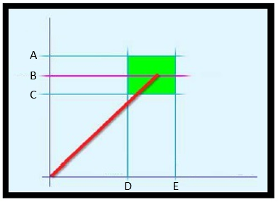
Torque vs. Angle A
Upper torque limit
B
Nominal
C
Lower torque limit
D
Lower angle limit
E
Upper angle limit
Using this method, it is possible to detect potential problems on the joint (refer to the following examples):
Torque is correct, but angle is too small:
|
|
|
|
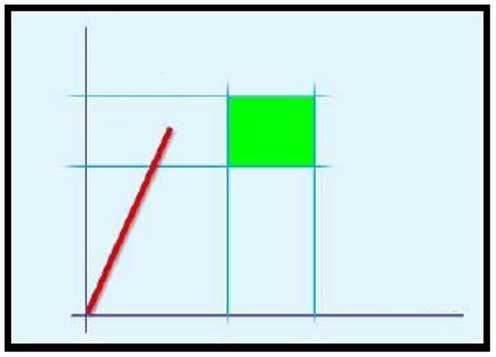
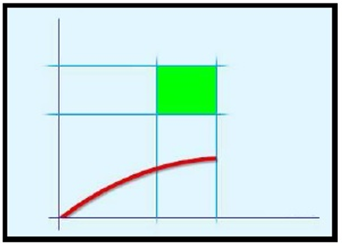
Tightening with torque and additional angle rotation (torque + angle): the bolt is first tightened to a certain torque and then it is further tightened to a specific angle. The goal is to stress the bolt over the yield point. Even with differences in the angle, the torque (causing clamping force) is quite reliable. Sometimes the joint is specially designed and the analysis of the joint helps making sure that strain is far away from the breaking point.

Torque vs. Angle Tightening to elastic limits (yield) : The bolt is tightened until its elastic limit is reached. This method is used when each bolt must achieve the maximum clamping force. This method is seldom used in the car industry (example: Connecting rods). It is more common in the aerospace industry.

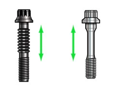 | These bolts are normally used in special applications and the shank of the bolt is designed with a special thin section to be stretched (this bolt works as a precise spring). |
Torque
This strategy guides the operator in reaching the desired target torque, without any angle reading.
Parameter | Description |
|---|---|
Required tag number | A specific number must be written in the TAG of the end fitting tool. |
Name | Name of the tightening program. |
Program start | Torque value from which the tightening operation starts. |
Torque min | Lower torque limit. |
Torque max | Higher torque limit. |
Maximum torque limit | If the torque applied reaches this limit, the message Change screw is shown on the wrench display. |
Target torque | The torque target. |
Torque units | This parameter is not editable. |
Torque correction coefficient | When extensions are used, the wrench measurement might be compensated to show a more accurate torque value. To calculate the correction coefficient, please refer to How to calculate the Torque Correction Coefficient. When extensions are not used, Torque correction coefficient = 1. |
Batch size | Number of tightenings the batch will perform. |
Max consecutive NOK | Number of accepted NOK to have an OK result. |
End cycle time | Starts when the torque goes below the Program start after reaching the 3rd percentage. |
Ratchet time | Starts when the torque goes below the Program start without reaching the 3rd percentage value. This allows the operator to release the torque for a while and recharge during the tightening operation. |

A | Torque max | B | Target torque |
C | Torque min | D | Program start |
The green area indicates the OK result area.
The torque result is the maximum torque measured during the tightening.
During the tightening operation, LEDs, buzzer and vibration are activated as follows:
LEDs:
White LED: activated when the torque value goes over the smartHEAD's Min load value.
First, second and third radial gradient LEDs turn green in sequence when the three thresholds defined for the tool in use are reached.
For further information, refer to Tool LEDs.All three radial gradient LEDs green: torque between Torque min and Torque max.
All three radial gradient LEDs red: torque over Torque max.
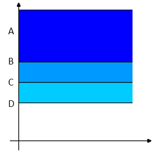
Torque vs. Angle A
Torque max
B
3rd percentage
C
2nd percentage
D
1st percentage
Buzzer
The beep starts when the torque goes over the Program start value; the signal increases when the 1st percentage, the 2nd percentage, the 3rd percentage, and the Torque max are reached.
Vibration:
Starts together with the third radial gradient LEDs.
At the end of the tightening operation, LEDs, buzzer and vibration are activated as follows:
LEDs behave according to the configuration of Result Indicator and Duration defined for the tool in use.
For further information, refer to Tool LEDs.Buzzer
Two beeps indicate the end of the operation; if the final result is in the red area, the signal in continuous.
To stop the buzzer, start a new tightening operation or press a button on the tool controller.
Vibration:
Stays active until the torque applied is released.
Torque (Control) / Angle (Monitor)
This strategy guides the operator in reaching the desired target torque while monitoring the angle.
Parameter | Description |
|---|---|
Required tag number | A specific number must be written in the TAG of the end fitting tool. |
Name | Name of the tightening program. |
Program start | Torque value from which the tightening operation starts. |
Torque min | Lower torque limit. |
Torque max | Higher torque limit. |
Maximum torque limit | If the torque applied reaches this limit, the message Change screw is shown on the wrench display. |
Target torque | The torque target. |
Trigger torque | Torque value from which the angle measurement starts (usually set to 50% of the Target torque). |
Angle min | Lower angle limit. |
Angle max | Higher angle limit. |
Torque units | This parameter is not editable. |
Angle limit for rehit | If the Torque min value is reached within the specified angle, the message Joint already tightened is shown on the wrench display. |
Stop condition | Select between Torque peak and Angle peak. |
Torque correction coefficient | When extensions are used, the wrench measurement might be compensated to show a more accurate torque value. To calculate the correction coefficient, please refer to How to calculate the Torque Correction Coefficient. When extensions are not used, Torque correction coefficient = 1. |
Angle correction | When extensions cause additional wrench bending, the wrench angle measurement can be compensated to show a more accurate angle value. When extensions are not used, Angle correction = 0. |
Batch size | Number of tightenings the batch will perform. |
Max consecutive NOK | Number of accepted consecutive NOK to have an OK result. |
End cycle time | Starts when the torque goes below the Program start after reaching the 3rd percentage. |
Ratchet time | Starts when the torque goes below the Program start without reaching the 3rd percentage value. This allows the operator to release the torque for a while and recharge during the tightening operation. |

A | Torque max | B | Target torque |
C | Torque min | D | Trigger torque |
E | Program start | F | Angle min |
G | Angle max |
The green area defines the OK result area.
During the tightening operation, LEDs, buzzer and vibration are activated as follows:
LEDs:
White LED: activated when the torque value goes over the smartHEAD's Min load value.
First, second and third radial gradient LEDs turn green in sequence when the three thresholds defined for the tool in use are reached.
For further information, refer to Tool LEDs.All three radial gradient LEDs green: torque between Torque min and Torque max and angle between Angle min and Angle max.
All three radial gradient LEDs red: torque over Torque max and angle over Angle max.

Torque vs. Angle A
Torque max
B
3rd percentage
C
2nd percentage
D
1st percentage
E
Program start
F
Angle max
Buzzer:
Starts when the torque goes over the Program start value; the signal increases when the 1st percentage, the 2nd percentage, the 3rd percentage, and the Angle max are reached.
Vibration:
Starts together with the third radial gradient LEDs.
Torque/angle results:
If the torque/angle does not exceed the torque/angle limits, the result is taken at the Torque peak or Angle peak (as specified in the tightening program).
If the torque/angle goes over the limit, the result is taken as follows:

Torque vs. Angle A
Torque max
B
Torque min
C
Trigger torque
D
Program start
E
Angle min
F
Angle max
G
When the Stop condition is set to Torque peak, and the torque (or both torque and angle) goes over the limits, the result is taken at the torque peak.
H
When the Stop condition is set to Torque peak , and only the angle goes over the limits, the result is taken at the angle peak.
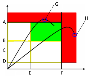
Torque vs. Angle A
Torque max
B
Torque min
C
Trigger torque
D
Program start
E
Angle min
F
Angle max
G
When the Stop condition is set to Angle peak, and the angle (or both torque and angle) goes over the limits, the result is taken at the angle peak.
H
When the Stop condition is set to Angle peak, and only the torque goes over the limits, the result is taken at the torque peak.
At the end of the tightening operation, LEDs, buzzer and vibration are activated as follows:
LEDs behave according to the configuration of Result Indicator and Duration defined for the tool in use.
For further information, refer to Tool LEDs.Buzzer
Two beeps indicate the end of the operation; if the final result is in the red area, the signal in continuous.
To stop the buzzer, start a new tightening operation or press a button on the tool controller.
Vibration:
Stays active until the torque applied is released.
Torque (Monitor) / Angle (Control)
This strategy guides the operator in reaching the desired target angle while monitoring the torque.
Parameter | Description |
|---|---|
Required tag number | A specific number must be written in the TAG of the end fitting tool. |
Name | Name of the tightening program. |
Program start | Torque value from which the tightening operation starts. |
Torque min | Lower torque limit. |
Torque max | Higher torque limit. |
Maximum torque limit | If the torque applied reaches this limit, the message Change screw is shown on the wrench display. |
Trigger torque | Torque value from which the angle measurement starts (usually set to 50% of the Target torque). |
Angle min | Lower angle limit. |
Angle max | Higher angle limit. |
Target angle | The angle target. |
Torque units | This parameter is not editable. |
Angle limit for rehit | If the Torque min value is reached within the specified angle, the message Joint already tightened is shown on the wrench display. |
Stop condition | Select between Torque peak and Angle peak. |
Torque correction coefficient | When extensions are used, the wrench measurement might be compensated to show a more accurate torque value. To calculate the correction coefficient, please refer to How to calculate the Torque Correction Coefficient. When extensions are not used, Torque correction coefficient = 1. |
Angle correction | When extensions cause additional wrench bending, the wrench angle measurement can be compensated to show a more accurate angle value. When extensions are not used, Angle correction = 0. |
Batch size | Number of tightenings the batch will perform. |
Max consecutive NOK | Number of accepted consecutive NOK to have an OK result. |
End cycle time | Starts when the torque goes below the Program start after reaching the 3rd percentage. |
Ratchet time | Starts when the torque goes below the Program start without reaching the 3rd percentage value. This allows the operator to release the torque for a while and recharge during the tightening operation. |
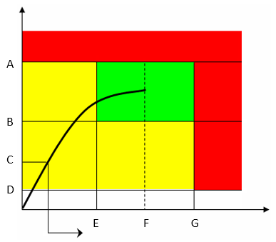
A | Torque max | B | Torque min |
C | Trigger torque | D | Program start |
E | Angle min | F | Target angle |
G | Angle max |
The green area defines the OK result area.
During the tightening operation, LEDs, buzzer and vibration are activated as follows:
LEDs:
White LED: activated when the torque value goes over the smartHEAD's Min load value.
First, second and third radial gradient LEDs turn green in sequence when the three thresholds defined for the tool in use are reached.
For further information, refer to Tool LEDs.All three radial gradient LEDs green: torque between Torque min and Torque max, and angle between Angle min and Angle max
All three radial gradient LEDs red: torque over Torque max and angle over Angle max.
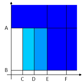
Torque vs. Angle A
Torque max
B
Program start
C
1st percentage
D
2nd percentage
E
3rd percentage
F
Angle max
Buzzer:
The beep starts when the torque goes over the Program start value; the signal increases when the 1st percentage, the 2nd percentage, the 3rd percentage, and the Torque max are reached.
Vibration:
Starts together with the third radial gradient LEDs.
Torque/angle results:
If the torque/angle does not exceed the torque/angle limits, the result is taken at the Torque peak or Angle peak (as specified in the tightening program).
If the torque/angle goes over the limit, the result is taken as follows:
Torque vs. Angle A
Torque max
B
Torque min
C
Trigger torque
D
Program start
E
Angle min
F
Angle max
G
When the Stop condition is set to Torque peak, and the torque (or both torque and angle) goes over the limits, the result is taken at the torque peak.
H
When the Stop condition is set to Torque peak, and only the angle goes over the limits, the result is taken at the angle peak.
Torque vs. Angle A
Torque max
B
Torque min
C
Trigger torque
D
Program start
E
Angle min
F
Angle max
G
When the Stop condition is set to Angle peak, and the angle (or both torque and angle) goes over the limits, the result is taken at the angle peak.
H
When the Stop condition is set to Angle peak, and only the torque goes over the limits, the result is taken at the torque peak.
At the end of the tightening operation, LEDs, buzzer and vibration are activated as follows:
LEDs behave according to the configuration of Result Indicator and Duration defined for the tool in use.
For further information, refer to Tool LEDs.Buzzer
Two beeps indicate the end of the operation; if the final result is in the red area, the signal is continuous.
To stop the buzzer, start a new tightening operation or press a button on the tool controller.
Vibration:
Stays active until the torque applied is released.
Torque + Angle
Using the Torque (Monitor) / Angle (Control) strategy, it is possible to achieve the Torque + Angle strategy.
Define the Trigger torque value as the torque value from which you want to start performing the “+ Angle” of this strategy:
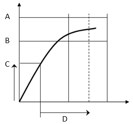
A | Torque max | B | Torque min |
C | Trigger torque | D | Target angle |
Torque (Control) / Angle (control) OR
This strategy guides the operator in reaching the desired target torque and angle.
Parameter | Description |
|---|---|
Required tag number | A specific number must be written in the TAG of the end fitting tool. |
Name | Name of the tightening program. |
Program start | Torque value from which the tightening operation starts. |
Torque min | Lower torque limit. |
Torque max | Higher torque limit. |
Maximum torque limit | If the torque applied reaches this limit, the message Change screw is shown on the wrench display. |
Target torque | The torque target. |
Trigger torque | Torque value from which the angle measurement starts (usually set to 50% of the Target torque). |
Angle min | Lower angle limit. |
Angle max | Higher angle limit. |
Target angle | The angle target. |
Torque units | This parameter is not editable. |
Angle limit for rehit | If the Torque min value is reached within the specified angle, the message Joint already tightened is shown on the wrench display. |
Stop condition | Select between Torque peak and Angle peak. |
Torque correction coefficient | When extensions are used, the wrench measurement might be compensated to show a more accurate torque value. To calculate the correction coefficient, please refer to How to calculate the Torque Correction Coefficient. When extensions are not used, Torque correction coefficient = 1. |
Angle correction | When extensions cause additional wrench bending, the wrench angle measurement can be compensated to show a more accurate angle value. When extensions are not used, Angle correction = 0. |
Batch size | Number of tightenings the batch will perform. |
Max consecutive NOK | Number of accepted consecutive NOK to have an OK result. |
End cycle time | Starts when the torque goes below the Program start after reaching the 3rd percentage. |
Ratchet time | Starts when the torque goes below the Program start without reaching the 3rd percentage value. This allows the operator to release the torque for a while and recharge during the tightening operation. |
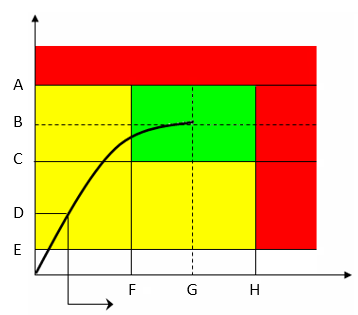
A | Torque max | B | Target torque |
C | Torque min | D | Trigger torque |
E | Program start | F | Angle min |
G | Target angle | H | Angle max |
The green area defines the OK result area.
During the tightening operation, LEDs, buzzer and vibration are activated as follows:
LEDs:
White LED: activated when the torque value goes over the smartHEAD's Min load value.
First, second and third radial gradient LEDs turn green in sequence when the three thresholds defined for the tool in use are reached.
For further information, refer to Tool LEDs.All three radial gradient LEDs green: torque between Torque min and Torque max, angle between Angle min and angle max.
All three radial gradient LEDs red: torque result over Torque max, or angle result over Angle max.
Torque peak:

Torque vs. Angle A
Torque max
B
Target torque
C
Torque min
D
2nd percentage
E
1st percentage
F
Program start
G
Angle min
H
Target angle
I
Angle max
Angle peak:
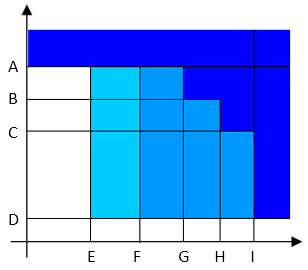
Torque vs. Angle A
Torque max
B
Target torque
C
Torque min
D
Program start
E
1st percentage
F
2nd percentage
G
Angle min
H
Target angle
I
Angle max
Buzzer:
The beep starts when the torque goes over the Program start value; the signal increases when the 1st percentage, the 2nd percentage, torque and angle are within the minimum and maximum limits, and the Torque max or Angle max are reached.
If Angle peak is specified in the tightening program, the buzzer signal monitors the angle instead of the torque.
Vibration:
Starts together with the third radial gradient LEDs.
Torque/angle results:
If torque/angle do not exceed the torque/angle limits, the result is taken at the Torque peak or Angle peak (as specified in the tightening program).
If the torque/angle goes over the limit, the result is taken as follows:
Torque vs. Angle A
Torque max
B
Torque min
C
Trigger torque
D
Program start
E
Angle min
F
Angle max
G
When the Stop condition is set to Torque peak, and the torque (or both torque and angle) goes over the limits, the result is taken at the torque peak.
H
When the Stop condition is set to Torque peak, and only the angle goes over the limits, the result is taken at the angle peak.
Torque vs. Angle A
Torque max
B
Torque min
C
Trigger torque
D
Program start
E
Angle min
F
Angle max
G
When the Stop condition is set to Angle, and the angle (or both torque and angle) goes over the limits, the result is taken at the angle peak.
H
When the Stop condition is set to Angle, and only the torque goes over the limits, the result is taken at the torque peak.
At the end of the tightening operation, LEDs, buzzer and vibration are activated as follows:
LEDs behave according to the configuration of Result Indicator and Duration defined for the tool in use.
For further information, refer to Tool LEDs.Buzzer:
Two beeps indicate the end of the operation; if the final result is in the red area, the signal is continuous.
To stop the buzzer, start a new tightening operation or press a button on the tool controller.
Vibration:
Stays active until the torque applied is released.
Torque (Control) / Angle (control) AND
This strategy guides the operator in reaching the desired target torque and angle.
Parameter | Description |
|---|---|
Required tag number | A specific number must be written in the TAG of the end fitting tool. |
Name | Name of the tightening program. |
Program start | Torque value from which the tightening operation starts. |
Torque min | Lower torque limit. |
Torque max | Higher torque limit. |
Maximum torque limit | If the torque applied reaches this limit, the message Change screw is shown on the wrench display. |
Target torque | The torque target. |
Trigger torque | Torque value from which the angle measurement starts (usually set to 50% of the Target torque). |
Angle min | Lower angle limit. |
Angle max | Higher angle limit. |
Target angle | The angle target. |
Torque units | This parameter is not editable. |
Angle limit for rehit | If the Torque min value is reached within the specified angle, the message Joint already tightened is shown on the wrench display. |
Stop condition | Select between Torque peak and Angle peak. |
Torque correction coefficient | When extensions are used, the wrench measurement might be compensated to show a more accurate torque value. To calculate the correction coefficient, please refer to How to calculate the Torque Correction Coefficient. When extensions are not used, Torque correction coefficient = 1. |
Angle correction | When extensions cause additional wrench bending, the wrench angle measurement can be compensated to show a more accurate angle value. When extensions are not used, Angle correction = 0. |
Batch size | Number of tightenings the batch will perform. |
Max consecutive NOK | Number of accepted consecutive NOK to have an OK result. |
End cycle time | Starts when the torque goes below the Program start after reaching the 3rd percentage. |
Ratchet time | Starts when the torque goes below the Program start without reaching the 3rd percentage value. This allows the operator to release the torque for a while and recharge during the tightening operation. |
A | Torque max | B | Target torque |
C | Torque min | D | Trigger torque |
E | Program start | F | Angle min |
G | Target angle | H | Angle max |
The green area defines the OK result area.
During the tightening operation, LEDs, buzzer and vibration are activated as follows:
LEDs:
White LED: activated when the torque value goes over the smartHEAD's Min load value.
First, second and third radial gradient LEDs turn green in sequence when the three thresholds defined for the tool in use are reached.
For further information, refer to Tool LEDs.All three radial gradient LEDs green: torque between Torque min and Torque max, angle between Angle min and angle max.
All three radial gradient LEDs red: torque over Torque max, or angle over Angle max.
Torque Peak:

Torque vs. Angle A
Torque max
B
Target torque
C
2nd percentage
D
1st percentage
E
Program start
F
Target angle
G
Angle max
Angle Peak:
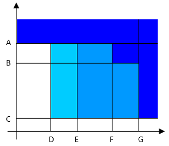
Torque vs. Angle A
Torque max
B
Target torque
C
Program start
D
1st percentage
E
2nd percentage
F
Target angle
G
Angle max
Buzzer:
The beep starts when the torque goes over the Program start value; the signal increases when the 1st percentage, the 2nd percentage, the angle and target values, and the Torque max are reached.
If Angle peak is specified in the tightening program, the buzzer signal monitors the angle instead of the torque.
Vibration:
Starts together with the third radial gradient LEDs.
Torque/angle results:
If the torque/angle does not exceed the torque/angle limits, the result is taken at the Torque Peak or Angle Peak (as specified in the tightening program).
If the torque/angle goes over the limit, the result is taken as follows:
Torque vs. Angle A
Torque max
B
Torque min
C
Trigger torque
D
Program start
E
Angle min
F
Angle max
G
When the Stop condition is set to Torque peak, and the torque (or both torque and angle) goes over the limits, the result is taken at the torque peak.
H
When the Stop condition is set to Torque peak, and only the angle goes over the limits, the result is taken at the angle peak.
Torque vs. Angle A
Torque max
B
Torque min
C
Trigger torque
D
Program start
E
Angle min
F
Angle max
G
When the Stop condition is set to Angle peak, and the angle (or both torque and angle) goes over the limits, the result is taken at the angle peak.
H
When the Stop condition is set to Angle peak, and only the torque goes over the limits, the result is taken at the torque peak.
At the end of the tightening operation, LEDs, buzzer and vibration are activated as follows:
LEDs behave according to the configuration of Result Indicator and Duration defined for the tool in use.
For further information, refer to Tool LEDs.Buzzer:
Two beeps indicate the end of the operation; if the final result is in the red area, the signal is continuous.
To stop the buzzer, start a new tightening operation or press a button on the tool controller.
Vibration:
Stays active until the torque applied is released.
Torque (Control) / Prevailing Torque (Monitor)
This strategy guides the operator in tightening joints with prevailing torque to the torque target value. It is particularly useful when the joint's prevailing torque value is higher than the final torque target.
The strategy calculates the prevailing torque value in a defined angle Window Length in order to subtract the prevailing torque value from the tightening's absolute peak torque value and confirm whether the desired torque target value is actually reached or not.
Parameter | Description |
|---|---|
Required tag number | A specific number must be written in the TAG of the end fitting tool. |
Name | Name of the tightening program. |
Program start | Torque value from which the tightening operation starts. |
Torque min | Lower torque limit. |
Torque max | Higher torque limit. |
Maximum torque limit | If the torque applied reaches this limit, the message Change screw is shown on the wrench display. |
Target torque | Torque target value. |
Trigger torque | Torque value from which the angle measurement starts (usually set to 50% of the Target torque). |
Delay monitoring | Angle value after which the angle reading must start. |
Start Angle Distance | Angle value that, spanning in reverse direction from the snug point, defines where the angle Window Lenght starts. |
Window Length | Angle interval during which the compensate value is calculated. |
Compensation | Method to define the tightening result:
|
High Limit | Upper torque limit value to get an OK result. High Limit must be > 0 |
Low Limit | Lower torque limit value to get an OK result. Low Limit must be ≥ 0 |
Use value | Method to define how to calculate the prevailing torque value in the angle Window Length interval:
|
Torque units | This parameter is not editable. |
Torque correction coefficient | When extensions are used, the wrench measurement might be compensated to show a more accurate torque value. To calculate the correction coefficient, please refer to How to calculate the Torque Correction Coefficient. When extensions are not used, Torque correction coefficient = 1. |
Angle correction | When extensions cause additional wrench bending, the wrench angle measurement can be compensated to show a more accurate angle value. When extensions are not used, Angle correction = 0. |
Batch size | Number of tightenings the batch will perform. |
Max consecutive NOK | Number of accepted consecutive NOK to have an OK result. |
End cycle time | Starts when the torque goes below the Program start after reaching the 3rd percentage. |
Ratchet time | Starts when the torque goes below the Program start without reaching the 3rd percentage value. This allows the operator to release the torque for a while and recharge during the tightening operation. |
The angle Window Length, in which the prevailing torque value is calculated, starts at the angle degrees set in Start Angle Distance measured in reverse direction from the snug point, which is automatically calculated by the system in real time. The angle window then spans in opposite direction for the angle degrees set in Window Length. The calculated prevailing torque value can be either the mean or the peak torque value measured during the Window Length according to the Use value set for the tightening operation.
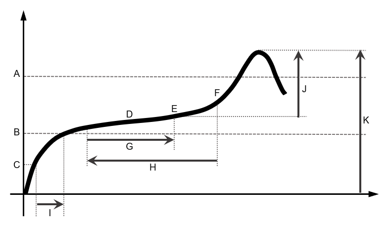
A | High limit | G | Window Length |
B | Low limit | H | Start Angle Distance |
C | Trigger torque | I | Delay monitoring |
D | Mean torque during angle Window Length | J | Peak torque value compensated with the subtraction of he prevailing torque. |
E | Peak torque during angle Window Length | K | Peak torque value without compensation. |
F | Snug point |
Torque results:
If Compensation is set to On, the calculated prevailing torque value is subtracted from the absolute peak torque value, and the torque final result value is the difference between the torque peak value and the prevailing torque value.
If Compensation is set to Off, the calculated prevailing torque value is not subtracted from the absolute peak torque value, and the torque final result value is the tightening's peak value.
During the tightening operation, LEDs, buzzer and vibration are activated as follows:
LEDs:
White LED: activated when the torque value goes over the smartHEAD's Min load value.
First, second and third radial gradient LEDs turn green in sequence when the three thresholds defined for the tool in use are reached.
For further information, refer to Tool LEDs.All three radial gradient LEDs green: torque between Low limit and High limit.
All three radial gradient LEDs red: torque over High limit.
Buzzer:
Starts when the torque goes over the Program start value; the signal increases when the 1st percentage, the 2nd percentage, the 3rd percentage.
Vibration:
Starts together with the third radial gradient LEDs.
At the end of the tightening operation, LEDs, buzzer and vibration are activated as follows:
LEDs behave according to the configuration of Result Indicator and Duration defined for the tool in use.
For further information, refer to Tool LEDs.Buzzer
Two beeps indicate the end of the operation; if the final result is in the red area, the signal in continuous.
To stop the buzzer, start a new tightening operation or press a button on the tool controller.
Vibration:
Stays active until the torque applied is released.
Loose
Parameter | Description |
|---|---|
Required tag number | A specific number must be written in the TAG of the end fitting tool. |
Name | Name of the tightening program. |
Program start | Torque value from which the tightening operation starts. |
Torque min | Lower torque limit. |
Torque max | Higher torque limit. |
Maximum torque limit | If the torque applied reaches this limit, the message Change screw is shown on the wrench display. |
Target angle | The angle target. |
Torque units | This parameter is not editable. |
Torque correction coefficient | When extensions are used, the wrench measurement might be compensated to show a more accurate torque value. To calculate the correction coefficient, please refer to How to calculate the Torque Correction Coefficient. When extensions are not used, Torque correction coefficient = 1. |
Angle correction | When extensions cause additional wrench bending, the wrench angle measurement can be compensated to show a more accurate angle value. When extensions are not used, Angle correction = 0. |
Batch size | Number of tightenings the batch will perform. |
End cycle time | Starts when the torque goes below the Program start after reaching the Target angle. |
Ratchet time | Starts when the torque goes below the Program start without reaching the Target angle value. |
This strategy is used to loosen a tightened screw. This is typically used in the sequence of a Multistep program.
For example:
Tighten the screw to 40 Nm
Loosen the screw by 30°
Tighten the screw to 50 Nm
The torque result is measured at the specified Target angle value.
If the Target angle is left at zero, this strategy automatically looks for torque / angle values to detect if the loosening process has been completed.
If a Target angle value is specified, loosening must reach the Target angle value in order to consider the result as OK.
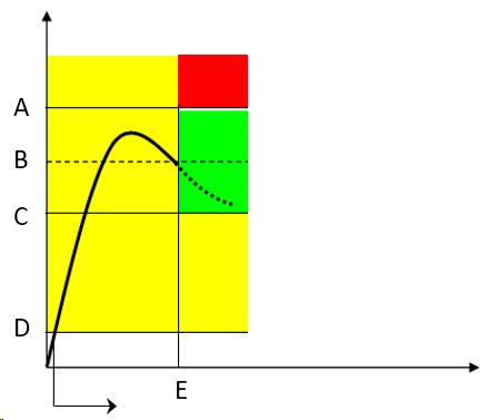
A | Torque max | B | Target torque |
C | Torque min | D | Program start |
E | Target angle |
The green area defines the OK result area.
During the tightening operation, LEDs, buzzer and vibration are activated as follows:
LED:
White LED: activated when the torque value goes over the smartHEAD's Min load value.
First, second and third radial gradient LEDs turn green in sequence when the three thresholds defined for the tool in use are reached.
For further information, refer to Tool LEDs.All three radial gradient LEDs green: torque between Torque min and Torque max.
All three radial gradient LEDs red: torque over Torque max.
Buzzer:
The beep starts when the torque goes over the Program start value; the signal increases when the Target angle is reached / the loosening process has been completed.
Vibration:
Starts when the Target angle is reached.
At the end of the tightening operation, LEDs, buzzer and vibration are activated as follows:
LEDs behave according to the configuration of Result Indicator and Duration defined for the tool in use.
For further information, refer to Tool LEDs.Buzzer
Two beeps indicate the end of the operation; if the final result is in the red area, the signal in continuous.
To stop the buzzer, start a new tightening operation or press a button on the tool controller.
Vibration:
Stays active until the torque applied is released.
Yield Point
This strategy guides the operator in tightening a joint to its yield point.
Parameter | Description |
|---|---|
Required tag number | A specific number must be written in the TAG of the end fitting tool. |
Name | Name of the tightening program. |
Program start | Torque value from which the tightening operation starts. |
Torque min | Lower torque limit. |
Torque max | Higher torque limit. |
Maximum torque limit | If the torque applied reaches this limit, the message Change screw is shown on the wrench display. |
Target torque | The torque target. |
Trigger torque | Torque value from which the angle measurement starts (usually set to 50% of the Target torque). |
Angle min | Lower angle limit. |
Angle max | Higher angle limit. |
Target angle | Angle value (measured from the detected yield point) that the tightening operation must reach in order to stop. Target angle must be > 0. |
Torque units | This parameter is not editable. |
Angle limit for rehit | If the Torque min value is reached within the specified angle, the message Joint already tightened is shown on the wrench display. |
Stop condition | Select between Torque peak and Angle peak. |
Linear slope coefficient | Coefficient that defines the joint stiffness in the linear part of the curve. The coefficient is meant as torque/angle slope and it is measured in Nm/°. Default value: 0.5. Minimum value: 0.1 (also suitable for very soft joints with a ration less than 0.1). If the selected unit of measurement is different from Nm, the Linear slope coefficient must always be converted into Nm/°. |
Torque correction coefficient | When extensions are used, the wrench measurement might be compensated to show a more accurate torque value. To calculate the correction coefficient, please refer to How to calculate the Torque Correction Coefficient. When extensions are not used, Torque correction coefficient = 1. |
Angle correction | When extensions cause additional wrench bending, the wrench angle measurement can be compensated to show a more accurate angle value. When extensions are not used, Angle correction = 0. |
Batch size | Number of tightenings the batch will perform. |
Max consecutive NOK | Number of accepted consecutive NOK to have an OK result. |
End cycle time | Starts when the torque goes below the Program start after reaching the 3rd percentage. |
Ratchet time | Starts when the torque goes below the Program start without reaching the 3rd percentage value. This allows the operator to release the torque for a while and recharge during the tightening operation. |

A | Torque max | E | Angle min |
B | Torque min | F | Target angle |
C | Torque trigger | G | Angle max |
D | Program start | H | Yield point |
The Target angle is measured from the detected yield point, while the Angle min and the Angle max are measured from the Trigger torque.
Define the torque limits to get and OK result.
Torque results:
If the yield point is detected and Target angle (measured from the detected yield point) is reached, the torque result is taken at Target angle.
If the operator stops the tightening after the yield point but before reaching Target angle, the torque result is the maximum measured torque.
If the torque exceeds the Maximum torque limit value, the yield point is no longer detected and the torque result is the maximum measured torque.
During the tightening operation, LEDs, buzzer and vibration are activated as follows:
LEDs
LEDs:
White LED: activated when the torque value goes over the smartHEAD's Min load value.
First, second and third radial gradient LEDs turn green in sequence when the three thresholds defined for the tool in use are reached.
For further information, refer to Tool LEDs.All three radial gradient LEDs green: torque between Torque min and Torque max.
All three radial gradient LEDs red: torque over Torque max.
Buzzer:
The beep starts when the torque goes over the Program start value; the signal increases when the Target angle is reached after detecting the yield point.
Vibration:
Starts when the Target angle is reached after detecting the yield point.
At the end of the test operation, LEDs, buzzer and vibration are activated as follows:
LEDs:
LEDs behave according to the configuration of Result Indicator and Duration defined for the tool in use.
For further information, refer to Tool LEDs.
Buzzer
Two beeps indicate the end of the operation; if the final result is in the red area, the signal in continuous.
To stop the buzzer, start a new tightening operation or press a button on the tool controller.
Vibration:
Stays active until the torque applied is released.
In the configuration of the Yield Point strategy, there is one advanced parameter: the Linear slope coefficient. This coefficient defines the joint stiffness in the linear part of the curve. The coefficient is meant as torque/angle slope, and it is measured in Nm/°. The minimum value is 0.1, which suits also very soft joints with a ratio smaller than 0.1. The default value is 0.5.
The Linear slope coefficient can be calculated experimentally for each single joint (only after running a trial test to get data for calculating it) as follows:

 = Linear slope coefficient
If the measuring unit selected for the operation is different from Nm, the Linear slope coefficient must be converted into Nm/°.
For instance, for a joint with a stiffness of 0.6 lbf*ft/°, since 1 lbf*ft = 1.3558 Nm, the Linear slope coefficient must be converted as follows:
0.6 lbf*ft/° → 0.6x1.3558 = 0.81 Nm/°
Quality Control Strategies
The aim of quality control strategies is either to check tightening operations already performed by testing the residual torque on joints, or to study joints' characteristics.
These strategies can be used only when the STRwrench is connected to an external controller.
Residual Torque / Angle
This strategy evaluates the residual torque on a joint, looking for the residual point of the Torque / Angle trace.
Parameter | Description |
|---|---|
Required tag number | A specific number must be written in the TAG of the end fitting tool. |
Name | Name of the tightening program. |
Program start | Torque value from which the tightening operation starts. |
Torque min | Lower torque limit. |
Torque max | Higher torque limit. |
Maximum torque limit | If the torque applied reaches this limit, the message Change screw is shown on the wrench display. |
Target torque | The torque target. |
Trigger torque | Torque value from which the angle measurement starts (usually set to 50% of the Target torque). |
Angle min | Lower angle limit. |
Angle max | Higher angle limit. |
Target angle | The angle target. |
Torque units | This parameter is not editable. |
Angle limit for rehit | If the Torque min value is reached within the specified angle, the message Joint already tightened is shown on the wrench display. |
Stop condition | Select between Torque peak and Angle peak. |
Breakaway angle threshold | The maximum angle for the residual torque (measured from the Trigger torque). |
Residual angle threshold | The maximum angle (measured from the Trigger torque) for the residual torque when the residual torque is lower than the breakaway point. |
Only breakaway for results | When this parameter is enabled, the detection of the residual point is disabled. |
Torque correction coefficient | When extensions are used, the wrench measurement might be compensated to show a more accurate torque value. To calculate the correction coefficient, please refer to How to calculate the Torque Correction Coefficient. When extensions are not used, Torque correction coefficient = 1. |
Angle correction | When extensions cause additional wrench bending, the wrench angle measurement can be compensated to show a more accurate angle value. When extensions are not used, Angle correction = 0. |
Batch size | Number of tightenings the batch will perform. |
Max consecutive NOK | Number of accepted consecutive NOK to have an OK result. |
End cycle time | Starts when the torque goes below the Program start after reaching the 3rd percentage. |
Ratchet time | Starts when the torque goes below the Program start without reaching the 3rd percentage value. This allows the operator to release the torque for a while and recharge during the tightening operation. |
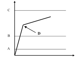
A | Program start | B | Torque min |
C | Torque max | D | Breakaway = Residual |
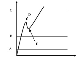
A | Program start | B | Torque min |
C | Torque max | D | Breakaway |
E | Residual |
Define the torque upper and lower limits to get an OK result.
The Trigger torque, which must be greater than the Program start, defines the point from which the device algorithm starts analyzing the torque/angle trace. This is useful to filter all the noise that may occur at low torque value, and that could be detected as a false residual point.
Torque result:
If the residual point is detected, the result is associated with the residual point; the test is OK if the residual falls within the limits.
If the residual is not detected or the torque goes over the maximum torque, the torque result is the maximum measured value. Therefore, if the maximum value falls within the limits, the torque result is still OK, but the overall result is marked as Not OK.
If the torque goes over the Maximum torque limit value, the residual is no longer detected and the torque result is the maximum torque.
In the configuration of the Residual torque/angle strategy, there are two advanced parameters:
Breakaway angle threshold: it specifies the maximum angle for the residual torque (measured from the Trigger torque).
Residual angle threshold: it specifies the maximum angle for the residual torque (measured from the Trigger torque) when the residual torque is lower than the breakaway point.
If the residual point precedes the Residual angle threshold, the residual torque is detected. This is the normal condition for a residual torque test.
If the residual point is over the Residual angle threshold, the breakaway point is the result of the test. In this case, the Residual angle threshold should be increased to detect the proper residual point.
If the breakaway point is over the Breakaway angle threshold, the residual point is not detected even if the residual point precedes the Residual angle threshold
During the test operation, LEDs, buzzer and vibration are activated as follows:
LED:
White LED: activated when the torque value goes over the smartHEAD's Min load value.
First, second and third radial gradient LEDs turn green in sequence when the three thresholds defined for the tool in use are reached.
For further information, refer to Tool LEDs.All three radial gradient LEDs green: torque between Torque min and Torque max.
All three radial gradient LEDs red: torque over Torque max.
Buzzer:
The beep starts when the torque goes over the Program start value; the signal increases when the residual torque is detected / the tightening process has been completed.
Vibration:
Starts when the residual torque is detected.
At the end of the test operation, LEDs, buzzer and vibration are activated as follows:
LEDs behave according to the configuration of Result Indicator and Duration defined for the tool in use.
For further information, refer to Tool LEDs.Buzzer
Two beeps indicate the end of the operation; if the final result is in the red area, the signal in continuous.
To stop the buzzer, start a new tightening operation or press a button on the tool controller.
Vibration:
Stays active until the torque applied is released.
Residual Point Detection Algorithm
To detect the torque/angle residual point, the STRwrench uses an algorithm that calculates the gradient αt of the torque/angle trace by linear regression each time a new sample is collected. The algorithm then calculates the average of six different αt values:

The αaverage value is used to identify the residual point.
Algorithm application scenarios
Scenario A
When high static friction builds up into the joint (for example due to lack of lubrication), as soon as the bolt moves the torque decreases and the real residual torque is lower than the peak torque necessary to overcome the static friction. In this cases, the STRwrench algorithm monitors the αaverage: if αaverage has a negative value, the algorithm waits until the αaverage goes back to a positive value. The point in which the αaverage goes back to a positive value is considered the residual torque point.

A | Maximum torque | B | Minimum torque |
C | Final angle monitoring torque | D | Cycle start |
Scenario B
Normally, during breakaway there is a rapid change of the gradient of the torque/angle function when the bolt starts moving. The STRwrench algorithm takes as breakaway point the point of maximum distance (d) between the torque/angle trace and the straight line drawn from graph's origin to the actual point of the trace. This distance must be greater than the threshold and must be consistent for more samples.
In addition, the average slope of the part of the trace after the breakaway point must be less than 60% of the average slope of the part of the trace before the breakaway point.
If all these conditions are met, the test ends and the breakaway/residual point is detected.
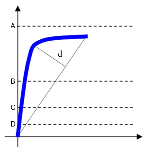
A | Maximum torque | B | Minimum torque |
C | Final angle monitoring torque | D | Cycle start |
d | Maximum distance between the trace and the straight line. | ||
Recommended settings
Cycle start | Set a value that is ≥ 2% of the smartHEAD capacity. |
Final angle monitoring torque | Set a value between Cycle start and Minimum torque. |
Minimum torque | Set the minimum residual torque value to get an OK result. |
Maximum torque | Set the maximum residual torque value to get an OK result. |
For instance, a proper setting for detecting the residual point on a bolt tightened to 50 N∙m using an STRwrench with a 80 N∙m smartHEAD could be the following:

A | Maximum torque | B | Minimum torque |
C | Final angle monitoring torque | D | Cycle start |
Residual Torque / Peak
This strategy evaluates the residual torque on a joint as the peak torque necessary to rotate the screw further.
Parameter | Description |
|---|---|
Required tag number | A specific number must be written in the TAG of the end fitting tool. |
Name | Name of the tightening program. |
Program start | Torque value from which the tightening operation starts. |
Torque min | Lower torque limit. |
Torque max | Higher torque limit. |
Maximum torque limit | If the torque applied reaches this limit, the message Change screw is shown on the wrench display. |
Target torque | The torque target. |
Trigger torque | Torque value from which the angle measurement starts (usually set to 50% of the Target torque). |
Angle min | Lower angle limit. |
Angle max | Higher angle limit. |
Target angle | The angle target. |
Torque units | This parameter is not editable. |
Angle limit for rehit | If the Torque min value is reached within the specified angle, the message Joint already tightened is shown on the wrench display. |
Stop condition | Select between Torque peak and Angle peak. |
Torque correction coefficient | When extensions are used, the wrench measurement might be compensated to show a more accurate torque value. To calculate the correction coefficient, please refer to How to calculate the Torque Correction Coefficient. When extensions are not used, Torque correction coefficient = 1. |
Angle correction | When extensions cause additional wrench bending, the wrench angle measurement can be compensated to show a more accurate angle value. When extensions are not used, Angle correction = 0. |
Batch size | Number of tightenings the batch will perform. |
Max consecutive NOK | Number of accepted consecutive NOK to have an OK result. |
End cycle time | Starts when the torque goes below the Program start after reaching the 3rd percentage. |
Ratchet time | Starts when the torque goes below the Program start without reaching the 3rd percentage value. This allows the operator to release the torque for a while and recharge during the tightening operation. |
With this strategy, the breakaway point is not detected automatically. Therefore, this is a less objective method of evaluating residual torque. It may be used when the residual torque/time or torque/angle methods cannot be performed.
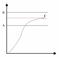
A | Torque min | B | Torque max |
C | Torque peak |
Define the torque limits to get an OK result.
If the Target angle value is not specified, the angle result is marked as Not Applicable.
If a Target angle value is specified, the residual torque result is measured at the specified angle (starting from the Trigger torque) instead of the peak torque:
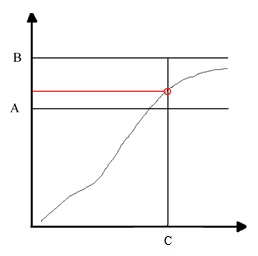
A | Torque min | B | Torque max |
C | Target angle |
During the test operation, LEDs, buzzer and vibration are activated as follows:
LED:
White LED: activated when the torque value goes over the smartHEAD's Min load value.
First, second and third radial gradient LEDs turn green in sequence when the three thresholds defined for the tool in use are reached.
For further information, refer to Tool LEDs.All three radial gradient LEDs green: torque between Torque min and Torque max.
All three radial gradient LEDs red: torque over Torque max.
Buzzer:
The beep starts when the torque goes over the Program start value; the signal increases when the residual torque is detected / the tightening process has been completed.
Vibration:
Starts when the residual torque is detected if a Target angle is specified.
At the end of the test operation, LEDs, buzzer and vibration are activated as follows:
LEDs behave according to the configuration of Result Indicator and Duration defined for the tool in use.
For further information, refer to Tool LEDs.Buzzer
Two beeps indicate the end of the operation; if the final result is in the red area, the signal in continuous.
To stop the buzzer, start a new tightening operation or press a button on the tool controller.
Vibration:
Stays active until the torque applied is released.
Yield Point (Joint Analysis)
This strategy evaluates the stiffness of a joint by measuring its yield point.
Parameter | Description |
|---|---|
Required tag number | A specific number must be written in the TAG of the end fitting tool. |
Name | Name of the tightening program. |
Program start | Torque value from which the tightening operation starts. |
Torque min | Lower torque limit. |
Torque max | Higher torque limit. |
Maximum torque limit | If the torque applied reaches this limit, the message Change screw is shown on the wrench display. |
Target torque | The torque target. |
Trigger torque | Torque value from which the angle measurement starts (usually set to 50% of the Target torque). |
Angle min | Lower angle limit. |
Angle max | Higher angle limit. |
Target angle | For joint analysis operation, Target angle is usually set to 0. |
Torque units | This parameter is not editable. |
Angle limit for rehit | If the Torque min value is reached within the specified angle, the message Joint already tightened is shown on the wrench display. |
Stop condition | Select between Torque peak and Angle peak. |
Linear slope coefficient | Coefficient that defines the joint stiffness in the linear part of the curve. The coefficient is meant as torque/angle slope and it is measured in Nm/°. Default value: 0.5. Minimum value: 0.1 (also suitable for very soft joints with a ration less than 0.1). If the selected unit of measurement is different from Nm, the Linear slope coefficient must always be converted into Nm/°. |
Torque correction coefficient | When extensions are used, the wrench measurement might be compensated to show a more accurate torque value. To calculate the correction coefficient, please refer to How to calculate the Torque Correction Coefficient. When extensions are not used, Torque correction coefficient = 1. |
Angle correction | When extensions cause additional wrench bending, the wrench angle measurement can be compensated to show a more accurate angle value. When extensions are not used, Angle correction = 0. |
Batch size | Number of tightenings the batch will perform. |
Max consecutive NOK | Number of accepted consecutive NOK to have an OK result. |
End cycle time | Starts when the torque goes below the Program start after reaching the 3rd percentage. |
Ratchet time | Starts when the torque goes below the Program start without reaching the 3rd percentage value. This allows the operator to release the torque for a while and recharge during the tightening operation. |

A | Torque max | C | Program start |
B | Torque min | D | Yield point |
Define the torque limits to get an OK result.
In joint analysis, instead of setting a narrow range with the torque upper and lower limits, define a wider area to detect the yield point.
Define a wide range for the angle upper and lower limits as well (for example, Angle min set to 0° and Angle max set to 999°).
During the tightening operation, LEDs, buzzer and vibration are activated as follows:
LED:
White LED: activated when the torque value goes over the smartHEAD's Min load value.
First, second and third radial gradient LEDs turn green in sequence when the three thresholds defined for the tool in use are reached.
For further information, refer to Tool LEDs.All three radial gradient LEDs green: torque between Torque min and Torque max.
All three radial gradient LEDs red: torque over Torque max.
Buzzer:
The beep starts when the torque goes over the Program start value; the signal increases when the yield point is detected / the tightening process has been completed.
Vibration:
Starts when the yield point is detected.
At the end of the test operation, LEDs, buzzer and vibration are activated as follows:
LEDs behave according to the configuration of Result Indicator and Duration defined for the tool in use.
For further information, refer to Tool LEDs.Buzzer
Two beeps indicate the end of the operation; if the final result is in the red area, the signal in continuous.
To stop the buzzer, start a new tightening operation or press a button on the tool controller.
Vibration:
Stays active until the torque applied is released.
In the configuration of the Yield Point strategy, there is one advanced parameter: the Linear slope coefficient. This coefficient defines the joint stiffness in the linear part of the curve. The coefficient is meant as torque/angle slope, and it is measured in Nm/°. The minimum value is 0.1, which suits also very soft joints with a ration smaller than 0.1. The default value is 0.5. The Linear slope coefficient may be calculated experimentally for each single joint (only after running a trial test to get data for calculating it) as follows:
= Linear slope coefficient
If the measuring unit selected for the operation is different from Nm, the Linear slope coefficient must be converted into Nm/°.
For instance, for a joint with a stiffness of 0.6 lbf*ft/°, since 1 lbf*ft = 1.3558 Nm, the Linear slope coefficient must be converted as follow:
0.6 lbf*ft/° → 0.6x1.3558 = 0.81 Nm/°
Correction Coefficients for Extensions
When the joint design or space limitations preclude the use of standard sockets or tools, it may be necessary to use special extension spanners to fit the application. In these cases, the STRwrench measurement can be adequately compensated since the factory calibration is made for the standard arm, and the extension arm increases the torque measured proportionally to its length. The angle measured could also be affected by the extensions, due to its specific torsion when torque is applied.
When a torque multiplier is used on the STRwrench, the torque applied on the joint is greater than the torque produced by the wrench; in this case the torque correction coefficient is used to adjust the wrench torque reading. The angle measurement is also affected, but the wrench cannot compensate the angle measurement.
How to calculate the Torque Correction Coefficient

D | Torque value displayed | T | Torque applied |
L | Standard arm (from the center of the handle to the center of the end fitting tool) | L+E | Total arm |
E | Extension arm |
From the relation between the displayed and applied torque  , the Torque correction coefficient is given by the following formula:
Torque correction coefficient = 
The Torque correction coefficient alters the wrench torque measurement; a wrong value for this coefficient may cause an improper torque reading, and the risk of doing a tightening at a target torque different from the one expected. Ensure you have calculated the proper value when an extension is used.
For end fitting tools used without wrench extensions, the Torque correction coefficient must be left set to 1.
When using an extension, the handling position affects the torque reading. Always position the hand on the center of the STRwrench handle.
If a torque multiplier is used on the STRwrench, the Torque Correction Coefficient must be set equal to the torque multiplying coefficient of the torque multiplier.
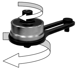
The Torque correction coefficient is given by the following formula:
Torque correction coefficient = Torqueoutput / Torqueinput
How to Calculate the Angle Correction
When a wrench extension is used, the Angle Correction allows linear compensation of the extension torsion based on the torque applied. The correction value is expressed in degrees at the smartHEAD Max torque.
On the Power Focus, configure a Torque (Control) / Angle (Monitor) tightening program with the following values:
Rundown complete torque = smartHEAD Min torque value (5% of smartHEAD Max torque)
Final angle monitoring torque = Rundown complete torque
Target torque = 75% of smartHEAD Max torque
Do three tightenings at 75% of the smartHEAD Max torque.
For each torque and angle value measured, do the following calculation:
Angle correction = Angle measured x (smartHEAD Max torque - smartHEAD Min torque) / (Torque measured - smartHEAD Min torque)
Make sure the minimum and maximum angle values calculated do not differ by more than 10% of the maximum value calculated:
Angle correctionmax - Angle correctionmin ≤ Angle correctionmax / 10
If they differ by more than 10%, repeat the procedure from the beginning.
Average the three angle values calculated to obtain the Angle correction.
When a torque multiplier is used on the STRwrench, the Angle correction value must be left to zero; in this case the STRwrench cannot compensate the angle measurement.
I/O Expander and Stacklight Signals
Output signals
Signal | Signal Type | Value Type | Size Min [bit] | Size Max [bit] | Meaning |
|---|---|---|---|---|---|
Batch Completed - 30 | Event | Boolean | 1 | 1 | Batch Completed is an output signal which is triggered when the batch is complete. The batch result status (OK or NOK) has no effect on the Batch Completed signal. |
Batch Completed NOK - 37 | Event | Boolean | 1 | 1 | Batch finished with status NOK. |
Batch Completed OK - 36 | Event | Boolean | 1 | 1 | Batch finished with status OK. |
Batch Running - 32 | State | Boolean | 1 | 1 | Indicates that a batch in a batch sequence is running. |
Batch Sequence Completed NOK - 46 | Event | Boolean | 1 | 1 | Batch sequence finished with status NOK. |
Batch Sequence Completed OK - 45 | Event | Boolean | 1 | 1 | Batch sequence finished with status OK. |
Batch Sequence Done - 48 | Event | Boolean | 1 | 1 | Indicates when a sequence is completed, both in case Batch Sequence Completed OK and Batch Sequence Completed NOK. |
Batch Sequence Running - 47 | State | Boolean | 1 | 1 | Indicates if the Batch Sequence is running or not. |
High Angle - 10 | Event | Boolean | 1 | 1 | Angle result is higher than maximum angle limit. |
High Torque - 7 | Event | Boolean | 1 | 1 | Torque result is higher than maximum torque limit. |
Identifier Received - 100 | Event | Boolean | 1 | 1 | Identifier received by the system. |
Low Angle - 9 | Event | Boolean | 1 | 1 | Angle result is lower than minimum angle limit. |
Low Torque - 6 | Event | Boolean | 1 | 1 | Torque result is lower than minimum torque limit. |
Max Consecutive NOK Reached - 35 | Event | Boolean | 1 | 1 | Max coherent NOK tightening counter is reached. |
Open Protocol Disconnected - 95 | State | Boolean | 1 | 1 | If Open Protocol is set to off in the Virtual Station, "Open Protocol Disconnected" signal is set to False. If Open Protocol is turned on in the Virtual Station the "Open Protocol Disconnected" signal is set to True. When at least one client (several Open Protocol clients can connect to the same Virtual Station) is connected the "Open Protocol Disconnected" signal is set to False |
Sequence Aborted - 160 | Event | Boolean | 1 | 1 | Sequence canceled. |
Tightening is Locked - 27 | State | Boolean | 1 | 1 | The tightening is disabled; it is not possible to make any tightening. |
Tightening NOK - 4 | Event | Boolean | 1 | 1 | At least one result of the tightening is outside the specified limits. |
Tightening OK - 3 | Event | Boolean | 1 | 1 | The result of the tightening is within the specified limits. |
Tool Battery Low - 90 | State | Boolean | 1 | 1 | Tool battery level below a certain threshold. |
Tool Disabled - 158 | State | Boolean | 1 | 1 | Tool Disabled is an output signal which is activated when the tool is externally disabled. |
Tool Enabled - 159 | State | Boolean | 1 | 1 | Tool Enabled is an output signal which is activated when the tool is not externally disabled. |
Tool Running - 23 | State | Boolean | 1 | 1 | Indicates that the tool is rotating (clockwise [CW] or counter-clockwise [CCW]). |
Input signals
Signal | Signal Type | Value Type | Size Min [bit] | Size Max [bit] | Description |
|---|---|---|---|---|---|
Abort sequence - 10012 | Event | Boolean | 1 | 1 | When a Batch sequence abort request is received, the Batch sequence functionality terminates the batch sequence only after getting the ongoing tightening result. |
Batch Decrement - 10002 | Event | Boolean | 1 | 1 | Incrementally decreases the batch counter by one. |
Batch Increment - 10001 | Event | Boolean | 1 | 1 | Incrementally increases the batch counter by one. |
Bypass Tightening Program - 10008 | Event | Boolean | 1 | 1 | Skips the next tightening program in the running batch sequence. |
Reset Batch - 10003 | Event | Boolean | 1 | 1 | Resets the batch counter to 0. No batch OK (nxOK). If batch OK is activated, it will be deactivated. |
Reset Batch Sequence - 10053 | Event | Boolean | 1 | 1 | Resets the Batch Sequence. |
Input/Output signals
Signal | Signal Type | Value Type | Size Min [bit] | Size Max [bit] | Description |
|---|---|---|---|---|---|
Disable Open Protocol Commands - 10060 | State | Boolean | 1 | 1 | Disables the possibility to send commands over Open Protocol to the Virtual Station. |
List of Third-Party Licenses
STRwrench controllers incorporate third-party components whose licenses require us to publish copies of the licensing language and/or copyright notices. In compliance with those requirements, here are copies of the licenses. Please, click on any of the licenses below to show a copy of the license text.
Software | Version | Licenses |
|---|---|---|
acl | 2.2.52 | |
alsa-lib | 1.1.2 | |
alsa-state | 0.2.0 | |
alsa-tools | 1.1.0 | |
alsa-utils | 1.1.2 | |
anybus | 1.1 |
|
atftp | 0.7.1 + gitAUTOINC + be3291a18c | |
attr | 2.4.47 | |
barebox | 2018.06.0 | |
base-files | 3.0.14 | |
base-files-px2-base | 1.0 | |
base-passwd | 3.5.29 | |
bash | 4.3.30 | |
bash-completion | 2.4 | |
bluez5 | 5.41 | |
boost | 1.61.0 | |
busybox-px2base | 1.24.1 | |
bzip2 | 1.0.6 | |
ca-certificates | 20160104 | |
cppunit | 1.13.1 | |
cryptodev-linux | 1.8 | |
curl | 7.50.1 | |
db | 3.0.35 | |
dbus | 1.10.10 | |
dhcp | 4.3.4 | |
dosfstools | 4.0 | |
dt-utils | 2017.03.0 | |
e2fsprogs | 1.43 | |
ecryptfs-tools | 1.0 | |
elfutils | 0.166 | |
eudev | 3.2.2 | |
expat | 2.2.0 | |
fbset | 2.1 | |
fb-test | 1.1.0 | |
fcgi | 2.4.0 | |
finit | 3.1 | |
firmware-imx | 5.4 |
|
flac | 1.3.1 | |
flatbuffers | 1.9.0 | |
fruit | 3.4.0 + gitAUTOINC + ece0f7218c | |
fuse | 2.9.4 | |
gcc-runtime | 6.2.0 | |
gdb | 8.0.1 | |
gdbm | 1.12 | |
glib-2.0 | 2.48.2 | |
glibc | 2.24 | |
gmp | 6.1.1 | |
gnutls | 3.5.3 | |
grep | 2.25 | |
gstreamer1.0 | 1.8.3 | |
gstreamer1.0-plugins-base | 1.8.3 | |
hostpad | 2.6 | |
htop | 1.0.3 | |
icu | 57.1 | |
init-ifupdown | 1.0 | |
initscripts | 1.0 | |
iproute2 | 4.7.0 | |
iptables | 1.6.0 | |
ipwatchd | 1.2 | |
iw | 4.7 | |
json-spirit | 4.08 | |
keyutils | 1.5.9 | |
kmod | 23 + gitAUTOINC + 65a885df5f | |
kmsfbwrap-px2base | 12.0 | |
libarchive | 3.2.2 | |
libbsd | 0.8.3 |
|
libcap | 2.25 | |
libdrm | 2.4.70 | |
libestr | 0.1.10 | |
libevent | 2.0.22 | |
libfastjson | 0.99.4 | |
libffi | 3.2.1 | |
libgcc | 6.2.0 | |
libgcrypt | 1.7.3 | |
libgpg-error | 1.24 | |
libidn | 1.33 | |
libite | 2.0.2 | |
libjpeg-turbo | 1.5.0 | |
liblogging | 1.0.5 | |
libnet | 1.2-rc3 | |
libnfsidmap | 0.25 | |
libnl | 3.2.28 | |
libogg | 1.3.2 | |
libpcap | 1.8.1 | |
libpcre | 8.39 | |
libpng | 1.6.24 | |
librcf | 2.2.0.0 | |
libsamplerate0 | 0.1.8 | |
libsndfile1 | 1.0.27 | |
libtinyxml | 2.6.2 | |
libtirpc | 1.0.1 | |
libuev | 2.2.0 | |
libusb1 | 1.0.20 | |
libvorbis | 1.3.5 | |
libxml2 | 2.9.4 | |
libxslt | 1.1.29 | |
lighttpd | 1.4.51 | |
linux-atlas | 4.14 | |
linux-libc-headers | 4.14.13 | |
logrotate | 3.9.1 | |
lua | 5.1.5 | |
luabind | git | |
lzo | 2.09 | |
lzop | 1.03 | |
memlog | 2.0 | |
mesa | 12.0.1 | |
mg | 20161005 |
|
minizip | 1.2.8 | |
mmc-utils | 0.1 | |
mtd-utils | 1.5.2 | |
nano | 2.2.5 | |
ncurses | 6.0 + 20160625 | |
netbase | 5.3 | |
netcat-openbsd | 1.105 | |
nettle | 3.2 | |
nfs-utils | 2.1.1 | |
ntp | 4.2.8p8 | |
openssh | 7.6p1 | |
openssl | 1.0.2n | |
opkg | 0.3.3 | |
opkg-arch-config | 1.0 | |
opkg-utils | 0.3.2 + gitAUTOINC + 3ffece9bf1 | |
orc | 0.4.25 | |
os-release | 1.0 | |
packagegroup-atlas-qt5 | 1.0 | |
packagegroup-atlas-sxb | 1.0 | |
packagegroup-base | 1.0 | |
packagegroup-core-boot | 1.0 | |
packagegroup-core-eclipse-debug | 1.0 | |
packagegroup-core-nfs | 1.0 | |
packagegroup-core-ssh-openssh | 1.0 | |
packagegroup-px2it | 1.0 | |
parted | 3.2 | |
perl | 5.22.1 | |
pm-utils | 1.4.1 | |
poco | 1.9.0 | |
pointercal | 0.0 | |
popt | 1.16 | |
procps | 3.3.12 | |
protobuf | 2.6.1 + gitAUTOINC + bba83652e1 | |
python | 2.7.12 | |
qtbase | 5.7.1 + gitAUTOINC + a55f36211e | |
qtdeclarative | 5.7.1 + gitAUTOINC + 2a992040e2 | |
qtlocation | 5.7.1 + gitAUTOINC + de5be121d8 | |
qtsensors | 5.7.1 + gitAUTOINC + 5a57beaaa5 | |
qtwebkit | 5.7.1 + gitAUTOINC + 76e2732f01 | |
qtwebsockets | 5.7.1 + gitAUTOINC + 60cede232a | |
qtxmlpatterns | 5.7.1 + gitAUTOINC + 89dbcc4f80 | |
rauc | 0.4 | |
readline | 6.3 | |
rpcbind | 0.2.3 | |
rsync | 3.1.2 | |
rsyslog | 8.22.0 | |
run-postinsts | 1.0 | |
shadow | 4.2.1 | |
shadow-security | 4.2.1 | |
sqlite3 | 3.14.1 |
|
squashfs-tools | 5.7.1 + gitrAUTOINC + 9c1db6d13a |
|
st-load | 1.0 |
|
stm32flash | git | |
strace | 4.13 | |
sysfsutils | 2.1.0 | |
sysvinit-bootlogd | 2.88dsf | |
tcf-agent | 1.4.0 + gitAUTOINC + 2dddd5f440 | |
tcpdump | 4.7.4 | |
tcp-wrappers | 7.6 | |
tslib | 1.1 | |
tzdata | 2016i |
|
u-boot-atlas | 2017.09 | |
u-boot-fw-utils | 2017.09 | |
unzip | 6.0 | |
usbutils | 008 | |
util-linux | 2.28.1 | |
wireless-tools | 30.pre9 | |
wpa-supplicant | 2.5 | |
xerces-c | 2.7.0 | |
xz | 5.2.2 |
|
yaml-cpp | 0.6.2 | |
zip | 3.0 | |
zlib | 1.2.8 |