Loose
Parameter | Description |
|---|---|
Required tag number | A specific number must be written in the TAG of the end fitting tool. |
Name | Name of the tightening program. |
Program start | Torque value from which the tightening operation starts. |
Torque min | Lower torque limit. |
Torque max | Higher torque limit. |
Maximum torque limit | If the torque applied reaches this limit, the message Change screw is shown on the wrench display. |
Target angle | The angle target. |
Torque units | This parameter is not editable. |
Torque correction coefficient | When extensions are used, the wrench measurement might be compensated to show a more accurate torque value. To calculate the correction coefficient, please refer to How to calculate the Torque Correction Coefficient. When extensions are not used, Torque correction coefficient = 1. |
Angle correction | When extensions cause additional wrench bending, the wrench angle measurement can be compensated to show a more accurate angle value. When extensions are not used, Angle correction = 0. |
Batch size | Number of tightenings the batch will perform. |
End cycle time | Starts when the torque goes below the Program start after reaching the Target angle. |
Ratchet time | Starts when the torque goes below the Program start without reaching the Target angle value. |
This strategy is used to loosen a tightened screw. This is typically used in the sequence of a Multistep program.
For example:
Tighten the screw to 40 Nm
Loosen the screw by 30°
Tighten the screw to 50 Nm
The torque result is measured at the specified Target angle value.
If the Target angle is left at zero, this strategy automatically looks for torque / angle values to detect if the loosening process has been completed.
If a Target angle value is specified, loosening must reach the Target angle value in order to consider the result as OK.
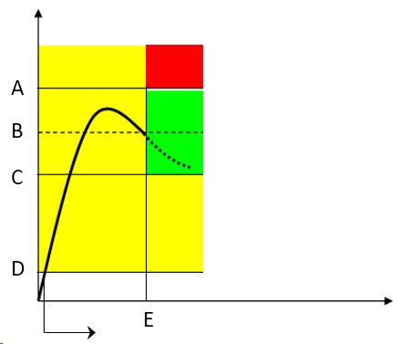
A | Torque max | B | Target torque |
C | Torque min | D | Program start |
E | Target angle |
The green area defines the OK result area.
During the tightening operation, LEDs, buzzer and vibration are activated as follows:
LED:
White LED: activated when the torque value goes over the smartHEAD's Min load value.
First, second and third radial gradient LEDs turn green in sequence when the three thresholds defined for the tool in use are reached.
For further information, refer to Tool LEDs.All three radial gradient LEDs green: torque between Torque min and Torque max.
All three radial gradient LEDs red: torque over Torque max.
Buzzer:
The beep starts when the torque goes over the Program start value; the signal increases when the Target angle is reached / the loosening process has been completed.
Vibration:
Starts when the Target angle is reached.
At the end of the tightening operation, LEDs, buzzer and vibration are activated as follows:
LEDs behave according to the configuration of Result Indicator and Duration defined for the tool in use.
For further information, refer to Tool LEDs.Buzzer
Two beeps indicate the end of the operation; if the final result is in the red area, the signal in continuous.
To stop the buzzer, start a new tightening operation or press a button on the tool controller.
Vibration:
Stays active until the torque applied is released.


