GFA-COT
Geared Front Attachment
Product Information
General Information
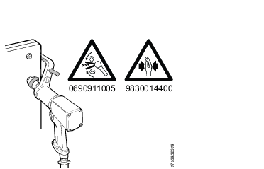
Safety Signal Words
The safety signal words Danger, Warning, Caution, and Notice have the following meanings:
DANGER | DANGER indicates a hazardous situation which, if not avoided, will result in death or serious injury. |
WARNING | WARNING indicates a hazardous situation which, if not avoided, could result in death or serious injury. |
CAUTION | CAUTION, used with the safety alert symbol, indicates a hazardous situation which, if not avoided, could result in minor or moderate injury. |
NOTICE | NOTICE is used to address practices not related to personal injury. |
Country of Origin
For the Country of Origin, please refer to the information on the product label.
Overview
System Description
The Gear Front Attachment (GFA) system is used for tightening and loosening of screws and nuts. The system can be used for screw connections in locations that are difficult to access.
The tightening operation is controlled by a separate drive unit to which the system is fitted. The drive unit can be of either pneumatic or electric type.
The modular structure of the system allows for a wide range of configurations available for different screw connections and tightening processes.
System Components
The modular GFA system is made up of the following main components:
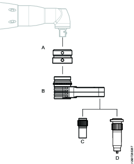
Position | Component | Function |
|---|---|---|
A | Adapter | With an adapter the GFA system can be fitted to different interfaces. The interface varies depending on the drive unit model. The adapter can be of either fixed index or quick index type. With a fixed index adapter the angle of the GFA system is specified from the factory. With a quick index adapter generation the operator can easily change the angle depending on the application. The adapters come in generation 1 and generation 2. |
B | Gear Front Attachment (GFA) head | The GFA head comes in various sizes for different torques and with different gear stages. |
C | Standard Socket | With different sockets the GFA system can be used for various screw profiles. |
D | Hold and Drive | With a hold and drive socket the screw is kept fixed while the nut is being tightened. |
GFA Shaft Lid generations
The closed end GFA module's shaft lid comes in two generations (1 and 2). Assembly of the GFA module with a shaft lid of generation 1 or 2 are the same, until the shaft lid is assembled on the module, then the assembly varies between generation 1 and 2.
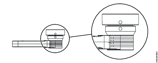
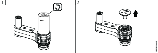
To identify the shaft lid generation
The shaft lid generation 1 does not have splines and the shaft lid is tightened with a pin spanner. The shaft lid generation 2 has splines and the shaft lid is assembled on the module by tightening two screws securing the shaft lid plate.
GFA Adapter generations
The fixed index adapter and quick index adapter come in generation 1 and generation 2.
Assembly of the fixed index adapter vary between generation 1 and generation 2. There is no difference in assembly instructions between the generations for the quick index adapter. For identification of adapter generation see information below.
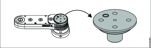
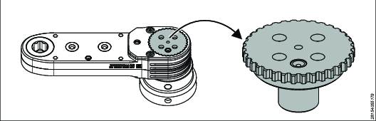
To identify fixed index adapter generation
Fixed adapter generation 2 can be identified from the exterior by the tracks. Generation 1 does not have this feature. See the pictures below.
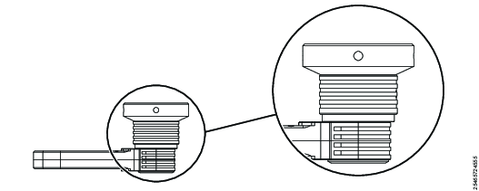
To identify quick index adapter generation
The adapter is generation 1, if the indexing function is activated by pulling the GFA. See the picture below.
The adapter is generation 2, if the indexing function is activated by pulling the indexing ring. See the picture below.
GFA performance
For maximum recommended torque see SI.
Accuracy 3σ: 7%.
Never exceed the recommended maximum torque.
The estimated product life of the COT is 500,000 tightenings.
The socket will be subject to wear and is therefore considered as a consumable product.
Installation
Installation Instructions
Assembling Instructions
Assembling the GFA Module with Shaft Lid generation 1
For service tool, see Service Equipment for the specific GFA model.
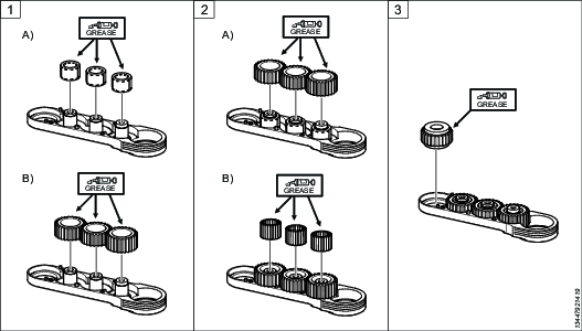
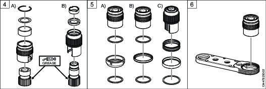
Depending on the type of needle bearings, assembled with needle carrier (A) or loose pins (B), do the following:
A) Add grease to the needle carrier. Put the needle carrier over the shafts.
B) Add grease to the middle gears. Put the middle gears over the shafts.
Depending on the type of needle bearings, assembled with needle carrier (A) or loose pins (B), do the following:
A) Add grease to the middle gears. Put the middle gears over the needle carriers.
B) Add grease to the needles. Insert the loose needles between the shafts and the middle gears. Make sure all the needles go in - there should be no gaps.
Add grease to the output gear. Place the output gear in the housing. Position the gear with the same orientation (hexagonal shape pointing up or down), as when dismantling.
Add grease to the input gear. Insert the input gear into the bearing housing and put back the snap ring, shim ring and needle carrier (if they were removed):
A) GFA system with fixed index or quick index adapter generation 1.
B) GFA system with fixed index or quick index adapter generation 2.
Depending on the adapter type the bearing house can be prepared in one of the following ways, before inserted into the GFA housing:
A) GFA system with fixed index adapter generation 1:
Insert the bearing housing into the upper locking ring, nut, and lower locking ring.B) GFA system with quick index adapter generation 1:
Insert the bearing housing into the upper locking ring, guide ring, and lower locking ring.C) GFA system with fixed index or quick index adapter generation 2:
Insert the bearing housing into the upper locking ring, guide ring, and lower locking ring.

Locking rings are not used in all GFA models, refer to the spare parts list of the GFA model in question.
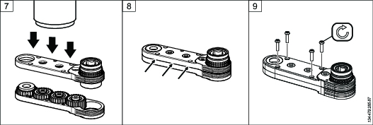
Insert the bearing housing, prepared as in the step above, into the GFA module housing.
The bearing housing can be inserted from the top or from below, depending on the GFA model.
Use a press tool to press the upper and lower parts of the housing together.
It is important to press evenly over the housing.
Make sure there is no gap between the upper and lower part of the housing.
Tighten the screws to the specified torque. The number and type of screws depend on the GFA model.
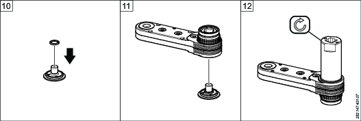
If applicable, put the bearing support washer over the shaft lid. The bearing support is not available of all GFA models.
Insert the shaft lid into the housing.
Turn the GFA upside down, put it in a vice and tighten the shaft lid.
Assembling the GFA Module with Shaft Lid generation 2
For service tool, see Service Equipment for the specific GFA model.
Depending on the type of needle bearings, assembled with needle carrier (A) or loose pins (B), do the following:
A) Add grease to the needle carrier. Put the needle carrier over the shafts.
B) Add grease to the middle gears. Put the middle gears over the shafts.
Depending on the type of needle bearings, assembled with needle carrier (A) or loose pins (B), do the following:
A) Add grease to the middle gears. Put the middle gears over the needle carriers.
B) Add grease to the needles. Insert the loose needles between the shafts and the middle gears. Make sure all the needles go in - there should be no gaps.
Add grease to the output gear. Place the output gear in the housing. Position the gear with the same orientation (hexagonal shape pointing up or down), as when dismantling.
Add grease to the input gear. Insert the input gear into the bearing housing and put back the snap ring, shim ring and needle carrier (if they were removed):
A) GFA system with fixed index or quick index adapter generation 1.
B) GFA system with fixed index or quick index adapter generation 2.
Depending on the adapter type the bearing house can be prepared in one of the following ways, before inserted into the GFA housing:
A) GFA system with fixed index adapter generation 1:
Insert the bearing housing into the upper locking ring, nut, and lower locking ring.B) GFA system with quick index adapter generation 1:
Insert the bearing housing into the upper locking ring, guide ring, and lower locking ring.C) GFA system with fixed index or quick index adapter generation 2:
Insert the bearing housing into the upper locking ring, guide ring, and lower locking ring.
Locking rings are not used in all GFA models, refer to the spare parts list of the GFA model in question.
Insert the bearing housing, prepared as in the step above, into the GFA module housing.
The bearing housing can be inserted from the top or from below, depending on the GFA model.
Use a press tool to press the upper and lower parts of the housing together.
It is important to press evenly over the housing.
Make sure there is no gap between the upper and lower part of the housing.
Tighten the screws securing the upper housing to the specified torque. The number and type of screws depend on the GFA model.
If applicable, put the bearing support washer over the shaft lid. The bearing support is not available for all GFA models.
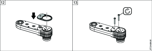
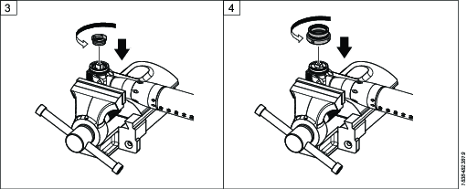
Turn the GFA module upside down. Insert the shaft lid into the housing. In the case that the GFA module has keys, check that the keys are in the correct position.
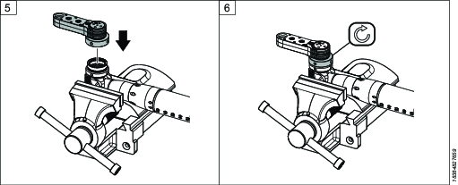
Put the shaft lid plate onto the shaft lid, the shaft lid should fit into the hole in the middle. Use a pin spanner to make sure that the shaft lid plate is in the correct position.
Tighten the screws securing the shaft lid plate to the specified torque.
Assemble COT250 GFA Module with Shaft lid generation 2
Apply grease to needle carrier and assemble the needle carrier over the shafts.
Apply grease to middle gears and assemble the middle gears over the needle carriers.
Add grease to the output gear. Place the output gear in the housing. Position the gear with the same orientation (hexagonal shape pointing up or down), as when dismantling.
Add grease to the input gear. Insert the input gear into the bearing housing and put back needle carrier (if they were removed):
A) GFA system with fixed index or quick index adapter generation 1.
B) GFA system with fixed index or quick index adapter generation 2.
Depending on the adapter type the bearing house can be prepared in one of the following ways, before inserted into the GFA housing:
GFA system with fixed index or quick index adapter generation 2:
Insert the bearing housing into the cover ring, index spring, quick index ring and spring ring.
Locking rings are not used in all GFA models, refer to the spare parts list of the GFA model in question.
Insert the bearing housing, prepared as in the step above, into the GFA module housing.
The bearing housing can be inserted from the top or from below, depending on the GFA model.
Use a press tool to press the upper and lower parts of the housing together.
It is important to press evenly over the housing.
Make sure there is no gap between the upper and lower part of the housing.
Tighten the housing with the help of screws, spacer and nut securing the upper housing to the specified torque. The number and type of screws depend on the GFA model.
If applicable, put the bearing support washer over the shaft lid. The bearing support is not available for all GFA models.
Turn the GFA module upside down. Insert the shaft lid into the housing. In the case that the GFA module has keys, check that the keys are in the correct position.
Put the shaft lid plate onto the shaft lid, the shaft lid should fit into the hole in the middle. Use a pin spanner to make sure that the shaft lid plate is in the correct position.
Tighten the screws securing the shaft lid plate to the specified torque.


Attaching a Fixed Index Adapter Generation 1 and 2
For service tool, see Service Equipment for the specific GFA model.
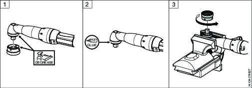
Clean the threads of the drive unit and the adapter.
Apply Loctite 2701, or similar, to the threads of the drive unit.
Fasten the drive unit in a vice and tighten the adapter to specified torque.
Attach the adapter to the nut.
Tighten the nut with a C-spanner to specified torque.
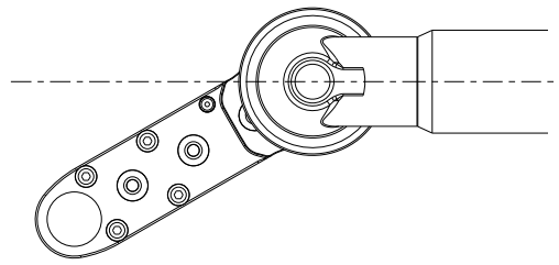
Attaching a Fork Adapter
For service tool, see Service Equipment for the specific GFA model.
Remove the bearing shell from the angle head of the tool.
Attach the fork adapter to the angle head.
Fasten the tool to a vice. Clean the threads. Apply Loctite 2701, or similar, to the bearing shell adapter, push it into the fork adapter and tighten to specified torque. Note: this is not the same bearing shell as the one for the angle head, in Step 1.
Clean the threads. Apply Loctite 2701, or similar, to the threads of the adapter. Screw it onto the fork adapter and tighten to specified torque, using a C-spanner.
Attach the nut with the GFA module to the adapter of the drive unit.
Tighten the nut, using a C-spanner.
Attaching a Quick Index Adapter Generation 1 and 2
For service tool, see Service Equipment for the specific GFA model.
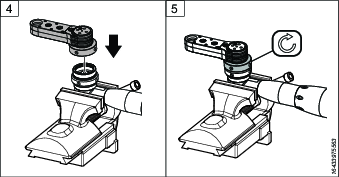
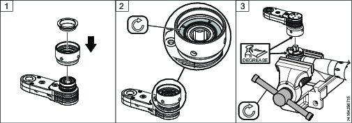
Attach the adapter and ring to the GFA unit.
Make sure the spring is inserted in the adapter before attaching the ring.
Tighten the ring inside the adapter to specified torque.
Fasten the drive unit to a vice. Clean the threads of the drive unit and the adapter.
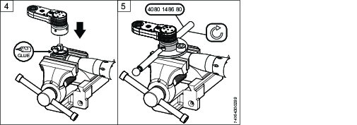
Apply Loctite 2701, or similar, to the threads of the drive unit.
Attach the adapter to the drive unit and use a C-spanner to tighten the adapter to specified torque.
Dismantling Instructions
Dismantling the GFA Module with Shaft lid generation 1
The instruction below shows an example of a GFA module. Details may vary depending on the GFA model.
For service tool, see Service Equipment for the specific GFA model.
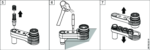
Loosen the shaft lid.
Remove the shaft lid.
Loosen and remove the screws. The number and type of screws depend on the GFA model.
Place the GFA module on a rubber mat. Hit the shafts to loosen the upper and lower part of the housing.
Separate the housings.
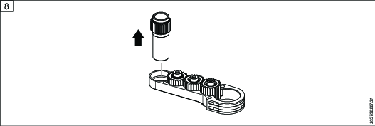
Remove the bearing housing and the snap ring, shim ring and needle carrier.
Remove the output gear, middle gears and input gears.
Note the direction of the output gear (hexagonal shape up or down). It should be placed in the same way when assembling the GFA module.
Remove the needle rollers.
Depending on the GFA model the needle rollers can be loose or assembled in bearing rings.


Dismantling the GFA Module with Shaft lid generation 2
The instruction below shows an example of a GFA module. Details may vary depending on the GFA model.
For service tool, see Service Equipment for the specific GFA model.
Loosen the screws securing the shaft lid plate.
Remove the shaft lid plate.
Remove the shaft lid.
Loosen the screws securing the upper housing. The number and type of screws depend on the GFA model.
Place the GFA module on a rubber mat. Hit the shafts to loosen the upper and lower part of the housing.
Separate the housings.
Remove the bearing housing and the snap ring, shim ring and needle carrier.
Remove the output gear, middle gears and input gears.
Note the direction of the output gear (hexagonal shape up or down). It should be placed in the same way when assembling the GFA module.
Remove the needle rollers.
Depending on the GFA model the needle rollers can be loose or assembled in bearing rings.
Dismantling COT250 GFA Module with Shaft lid generation 2
For service tool, see Service Equipment for the specific GFA model.
Loosen the screws securing the shaft lid plate.
Remove the shaft lid plate.
Remove the shaft lid.
Loosen the screws and remove spacer and nut securing the upper housing. The number and type of screws depend on the GFA model.
Place the GFA module on a rubber mat. Hit the shafts to loosen the upper and lower part of the housing.
Separate the housings.
Remove the bearing housing and the cove ring, index spring, quick index ring and spring ring.
Remove the output gear, middle gears and input gears.
Note the direction of the output gear (hexagonal shape up or down). It should be placed in the same way when assembling the GFA module.
Remove the needle rollers.
Depending on the GFA model the needle rollers can be loose or assembled in bearing rings.


Removing a Fixed Index Adapter Generation 1 and 2
For service tool, see Service Equipment for the specific GFA model.
Fasten the drive unit, together with the GFA system, in a vice.
Loosen the nut from the adapter using a C-spanner.
Remove the GFA unit from the adapter.
Loosen the adapter with a C-spanner to remove it from the drive unit.
The adapter is fixed to the drive unit with Loctite. Loosening the tool from the adapter requires strong force. It is recommended to use a heat gun to facilitate the loosening.
Removing a Fork Adapter
For service tool, see Service Equipment for the specific GFA model.
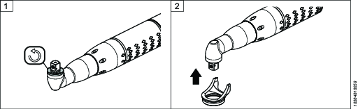
Fasten the drive unit in a vice and loosen the nut, using a C-spanner.
Remove the GFA module.
Loosen and remove the adapter from the fork adapter, using a C-spanner.
The adapter is fixed with Loctite. Loosening the adapter requires strong force. It is recommended to use a heat gun to facilitate the loosening.
Loosen and remove the bearing shell adapter from the fork adapter, using a C-spanner.
The bearing shell is fixed with Loctite. Loosening the bearing shell requires strong force. It is recommended to use a heat gun to facilitate the loosening.
Remove the fork adapter from the angle head.
If applicable, fasten the tool's bearing shell to the angle head. Note: this is not the same bearing shell as the one for the adapter, in Step 4.
Removing a Quick Index Adapter Generation 1 and 2
For service tool, see Service Equipment for the specific GFA model.
Fasten the drive unit together with the GFA system, in a vice. Use a C-spanner to loosen the adapter from the drive unit.
The adapter is fixed to the drive unit with Loctite. Loosening the adapter from the drive unit requires strong force. It is recommended to use a heat gun to facilitate the loosening.
Remove the adapter from the drive unit.
Loosen the ring inside the adapter.
Remove the ring and the adapter from the GFA unit.
Assembling XB-P Adapter Instructions
Preparation
For the COT assembly, remove the existing nose nut from the XB-P tool.

Attaching a XB-P Adapter
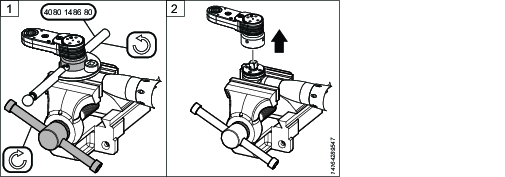
Fit the rotation locking ring to the XB-P housing. Slide the four internal fins into the corresponding grooves in the housing.

Tighten the nose nut to the XB-P housing using the following procedure:
Tighten to 20 Nm (counterclockwise) using a pin spanner.
Use the assembly tool 4080 1471 80 to tighten the nose nut.
Wait a minimum of 10 minutes (without loosening the initial applied torque).
Retighten to 20 Nm (counterclockwise) using a pin spanner.
The two-step tightening process is important because the plastic housing may relax after the first tightening.
When tightening, secure the rotation locking ring with a C-spanner.
For COT, temporarily remove the bit holder to access the nose nut. When using assembly tool 4080 1471 80, you can tighten the nose nut directly without removing the bit holder.

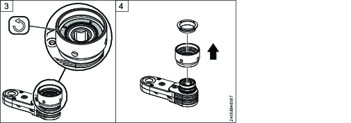
Insert the shaft into the bit holder to lock the shaft axially.

Tighten the threaded bushing to the rotation locking ring:
Apply Loctite 243 to the threads.
Tighten to 20 Nm in a counterclockwise direction.
When tightening, secure the rotation locking ring with a C-spanner.

Align the GFA with shaft. Make sure that shaft fits into the input gear of GFA. Tighten the adapter ring to the threaded bushing. For more details refer Assembling Instructions.
When tightening, secure the threaded bushing with a C-spanner.
Removing a XB-P Adapter
To remove the adapter from the XB-P tool, follow the assembly steps in reverse order.
Screw Tightening Instructions
For tightening the screws in the GFA module housings, see tightening torque in the table below.
GFA model | Screw Tightening Torque [Nm] |
|---|---|
COT14 | 1 |
COT26 | 1.3 |
COT41 | 1.3 |
COT62 | 2 |
COT81 | 2 |
COT250 | 4.8 |
Adapter Tightening Instructions
Crowfoot | Index locking ring (Quick Index Adapter) 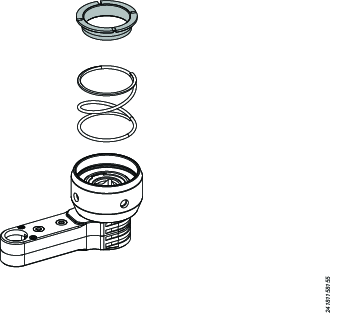 | Bearing Shell Fork Adapter 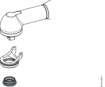 | Fixed Index Adapter 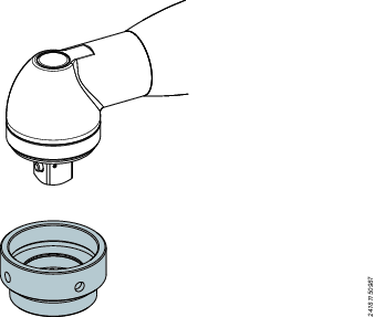 | Quick Index Adapter 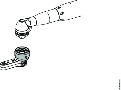 | Nut for Fix Index Adapter 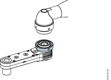 |
COT-14 | 10 Nm Loctite 243 | Acc. to tool spec. | 30 Nm Loctite 2701 | 20 Nm Loctite 243 | |
COT-26 | 10 Nm Loctite 243 | Acc. to tool spec. | 40 Nm Loctite 2701 | 30 Nm Loctite 243 | |
COT-41 | 10 Nm Loctite 243 | Acc. to tool spec. | 60 Nm Loctite 2701 | 30 Nm Loctite 243 | |
COT-62 | 15 Nm Loctite 243 | Acc. to tool spec. | 80 Nm Loctite 2701 | 40 Nm Loctite 243 | |
COT-81 | 15 Nm Loctite 243 | Acc. to tool spec. | 110 Nm Loctite 2701 | 40 Nm Loctite 243 | |
COT-250 | 20 Nm Loctite 243 | - | 250 Nm Loctite 2701 | - | |
Find the spline engagement closest to the specified position (angle).
Tighten the adapter to specified torque.
If the closest spline engagement is not a specified position (angle), tighten the adapter slightly more to the driving tool to align the driving tool and GFA.
Functional Test
The functional test is done on the GFA module disconnected from the tool.
Perform a functional test before the first tightening operation, and after any performed maintenance activities.
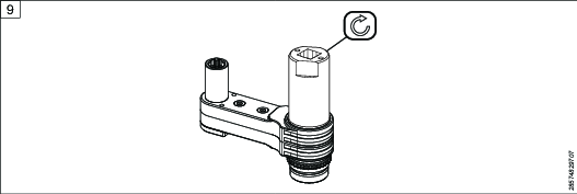
Turn the output gear wheel by hand or by using a socket. It should be turned easily.

If it is hard to turn, open the housing and check that all components are in the correct position. If issues persist, contact Atlas Copco Customer Center.
Lubricate the system.
Operation
Ergonomic Guidelines
Consider your workstation as you read through this list of general ergonomic guidelines to identify areas for improvement in posture, component placement, or work environment.
Take frequent breaks and change work positions frequently.
Adapt the workstation area to your needs and the work task.
Adjust for a convenient reach range by determining where parts and tools need to be located to avoid static load.
Use workstation equipment such as tables and chairs appropriate for the work task.
Avoid work positions above shoulder level or with static holding during assembly operations.
When working above shoulder level, reduce the load on the static muscles by lowering the weight of the tool, using for example torque arms, hose reels or weight balancers. You can also reduce the load on the static muscles by holding the tool close to the body.
Take frequent breaks.
Avoid extreme arm or wrist postures, particularly during operations requiring a degree of force.
Adjust for a convenient field of vision that requires minimal eye and head movements.
Use appropriate lighting for the work task.
Select the appropriate tool for the work task.
In noisy environments, use ear protection equipment.
Use high-quality inserted tools and consumables to minimize exposure to excessive levels of vibration.
Minimize exposure to reaction forces.
When cutting:
A cut-off wheel can get stuck if the cut-off wheel is bent or not guided properly. Always use the correct flange for the cut-off wheel and avoid bending the cut-off wheel during operation.
When drilling:
The drill might stall when the drill bit breaks through. Use support handles if the stall torque is high. The safety standard ISO11148 part 3 recommends using a device to absorb a reaction torque above 10 Nm for pistol grip tools and 4 Nm for straight tools.
When using direct-driven screwdrivers or nutrunners:
Reaction forces depend on the tool settings and joint characteristics. Strength and posture determine the amount of reaction force that an operator can tolerate. Adapt the torque setting to the operator's strength and posture and use a torque arm or reaction bar if the torque is too high.
In dusty environments, use a dust extraction system or wear a mouth protection mask.
Operating Instructions
Operating the GFA System
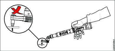
Bending on socket will reduce installed torque for all models.
If the operator puts a bending load on the socket (for example by not holding the tool weight, and letting the tool hang on the screw head) it will reduce the installed torque level. Even though the tool measures and reports a correct torque, the joint will not be properly tightened. This effect is more sensitive at low target torques.
Adjusting the Quick Index Adapter
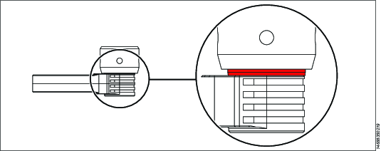
Unlock the GFA head: pull the GFA head down for generation 1 or pull down the index ring for generation 2.
Turn the GFA head and adjust the angle to the driving unit.

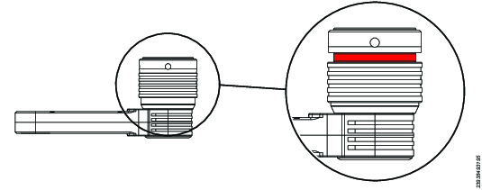
Lock the GFA head: pull the GFA head up for generation 1 or pull the index ring up for generation 2, and make sure the GFA head engages in the splines. In locked position the GFA head is not able to rotate, and the red ring is not visible from the side.
Quick Index adapter generation 1 in locked and unlocked position. Quick Index adapter generation 2 in locked and unlocked position. After each indexing, make sure the GFA head is in locked position before starting the tool.
Operating the GFA System with reaction bar
For angle tools using torque levels exceeding 50 Nm it is recommended to use a reaction bar, either mounted on the GFA reaction flange or on the tool.

Attach the tool to the application.
-
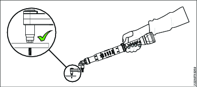
By using the reverse lever, the tool can be operated in both clockwise and counter-clockwise directions.
Make sure the tool is placed in the correct position on the work surface as described in the picture.
-
Press the push button to start the tool.
Continue pressing the push button while running down the nut. With pneumatic tools you can hear a sound, while the tool is running the nut down. When the sound decreases, release the push button to stop the tool. With electric tools the run down of the nut is controlled by the Power Focus.
Service
Service Overview
As the gear wheels of the GFA module are exposed to high surface pressure it is important to regularly check their condition. If any of the gear wheels are worn or damaged, all the gear wheels must be replaced. Needle bearings are to be replaced if damaged.
Unused gears may be subject to efficiency drift during break-in. After changing any of the input gear/socket/gears during service, it is recommended to increase the frequency of the calibration intervals during the first 3,000 tightenings.
At regular intervals between the service, additional grease is to be supplied through the grease nipples.
Service Instructions and Intervals
In case of faulty tightening results:
Inspect the input gear, output gear, and all interior parts for wear and change worn parts.
Daily service
Clean the GFA exterior.
Inspect the GFA for any damage.
Inspect all tightening elements on the GFA and the connection to the tool.
Run functional tests and listen for any abnormal noise.
Lubricate the system.
Yearly service
Clean the GFA interior.
Lubricate the GFA interior.
Run the GFA without load for 5 min to distribute the grease.
Calibrate the GFA to ensure correct torque.
Environment dependent service
Environment | Service interval |
|---|---|
Very dirty (e.g. heavy industry/outdoor environment) | Every 50,000 tightenings |
Dirty (e.g. industry where material removal on the same premises) | Every 125,000 tightenings |
Clean (e.g. typical assembly line) | Every 250,000 tightenings |
Very Clean (e.g. lab environment/office environment) | Every 500,000 tightenings |
Clean the GFA interior.
Lubricate the GFA interior.
Run the GFA without load for 5 min to distribute the grease.
Calibrate the GFA to ensure correct torque.
Maintenance Instructions
Changing a HAD Socket Bit
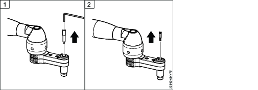
Loosen and remove the set screw from the socket, using an index key.
Remove the bit.
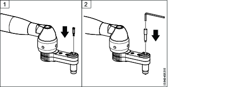
Insert the bit into the socket.
Insert the set screw into the socket and tighten.
Cleaning the System
Clean the exterior of the GFA
To clean the system, wipe carefully with a clean, smooth cloth.
Clean the interior of the GFA
It is recommended to use hand washer or ultrasonic cleaner as grease remover.
Dismantle the GFA system.
Clean the interior of the housing with grease remover.
Clean the cogs, needles and bearings separately with grease remover.
Clean parts from eventual remainder of grease remover, use brake cleaner or equivalent.
Assemble the GFA system.
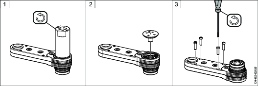
Changing a HAD Socket on a GFA Module with Shaft lid generation 1
To Remove the Socket:
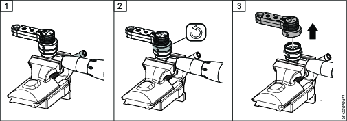
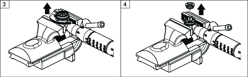
Loosen the shaft lid with a pin spanner.
Remove the shaft lid.
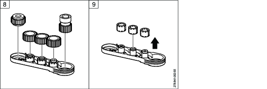
Remove the screws securing the housings and the HAD attachment plate.
The spring in the HAD socket will push the HAD attachment plate upwards. Ensure that the HAD attachment plate does not fly away.
A) If the HAD socket is an upward-facing socket, the screws securing the HAD attachment plate are put on the top.
B) If the HAD socket is a downward-facing socket, the screws securing the HAD attachment plate are put on top and on the bottom of the GFA module.
Remove the HAD attachment plate.
Remove the spring and the bit holder.
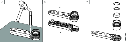
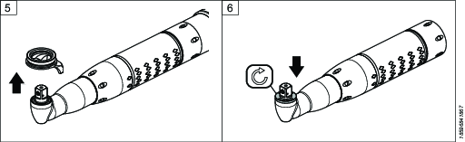
Place the GFA module on a rubber mat. Hit the shafts using a mandrel to loosen the upper and lower parts of the housing.
Separate the housings.
Remove the HAD socket.

To Install the Socket:
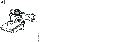
Add grease to the gear teeth and sliding surfaces of the HAD socket.
Put the new HAD socket in the housing together with the gears.
Use a press tool to press the upper and lower parts of the housing together.
It is important to press evenly over the housing.
Make sure there is no gap between the upper and lower part of the housing.
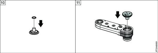
Insert the bit holder and the spring into the HAD socket.
Put the attachment plate on top of the spring, pressing it down.
Tighten the screws securing the housings and the HAD attachment plate to the specified torque:
A) If the HAD socket is an upward-facing socket, the screws securing the HAD attachment plate are put on the top.
B) If the HAD socket is a downward-facing socket, the screws securing the HAD attachment plate are put on top and on the bottom of the GFA module.
Insert the shaft lid into the housing.
Turn the GFA upside down, put it in a vice and tighten the shaft lid with a pin spanner.


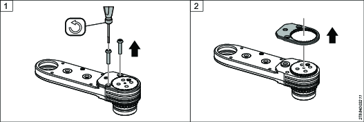
Changing a HAD Socket on the GFA Module with Shaft lid generation 2
To Remove the Socket:
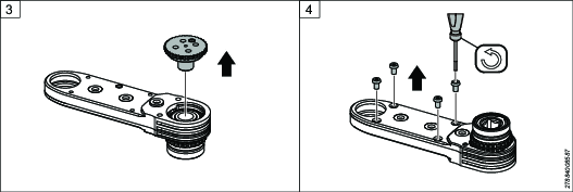
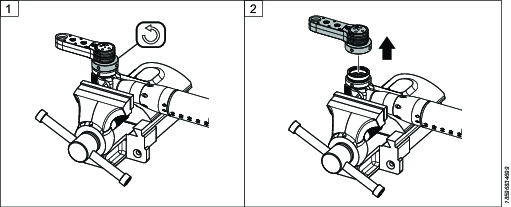
Remove the screws securing the shaft lid plate.
Remove the shaft lid plate.
Remove the shaft lid.
Remove the screws securing the housings and the HAD attachment plate. For COT250, also remove the spacer and nut.
The spring in the HAD socket will push the HAD attachment plate upwards. Ensure that the HAD attachment plate does not fly away.
A) If the HAD socket is an upward-facing socket, the screws securing the HAD attachment plate are put on the top.
B) If the HAD socket is a downward-facing socket, the screws securing the HAD attachment plate are put on top and on the bottom of the GFA module.
Remove the HAD attachment plate.
Remove the spring and the bit holder.
Place the GFA module on a rubber mat. Hit the shafts using a mandrel to loosen the upper and lower part of the housing.
Separate the housings.
Remove the HAD socket.


To Install the Socket:
Add grease to the gear teeth and sliding surfaces of the HAD socket.
Put the new HAD socket in the housing together with the gears.
Use a press tool to press the upper and lower parts of the housing together.
It is important to press evenly over the housing.
Make sure there is no gap between the upper and lower part of the housing.
Insert the bit holder and the spring into the HAD socket.
Put the attachment plate on top of the spring, pressing it down.
Tighten the screws securing the housings and the HAD attachment plate to the specified torque. For COT250, also assemble the spacer and nut with screws.
A) If the HAD socket is an upward-facing socket, the screws, spacer and nut securing the HAD attachment plate are put on the top.
B) If the HAD socket is a downward-facing socket, the screws, spacer and nut securing the HAD attachment plate are put on top and on the bottom of the GFA module.
Turn the GFA module upside down. Insert the shaft lid into the housing. In the case that the GFA module has keys, check that the keys are in the correct position.
Put the shaft lid plate onto the shaft lid, the shaft lid should fit into the hole in the middle. Use a pin spanner to make sure that the shaft lid plate is in the correct position.
Tighten the screws securing the shaft lid plate to the specified torque.


Lubrication Instructions
Lubrication for GFA
Component | Recommended | Quantity |
|---|---|---|
GFA module | Molykote Longterm 2 Plus | Until excess grease emerges on the output socket. |
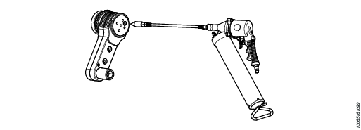
Use a grease gun to apply lubrication to every grease nipple of the GFA module.
The number of grease nipples varies with the design of the GFA module.
Run the system without load to distribute the grease.
Remove any excess grease from the exterior with a clean, smooth cloth.
Recycling
Environmental Regulations
When a product has served its purpose it has to be recycled properly. Dismantle the product and recycle the components in accordance with local legislation.
Batteries shall be taken care of by your national battery recovery organization.
Recycling Information
Fixed and quick index adapter generation 1
Recycle the GFA as steel.
Fixed and quick index adapter generation 2
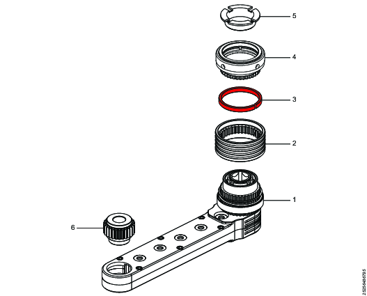
Pos. | Recycle as |
|---|---|
1-2, 4-6 | Steel |
3 | Aluminium |