Dismantling Instructions
Dismantling the GFA Module with Shaft lid generation 1
The instruction below shows an example of a GFA module. Details may vary depending on the GFA model.
For service tool, see Service Equipment for the specific GFA model.
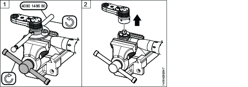
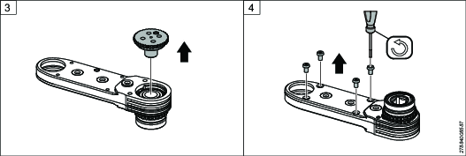
Loosen the shaft lid.
Remove the shaft lid.
Loosen and remove the screws. The number and type of screws depend on the GFA model.
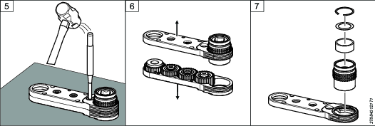
Place the GFA module on a rubber mat. Hit the shafts to loosen the upper and lower part of the housing.
Separate the housings.
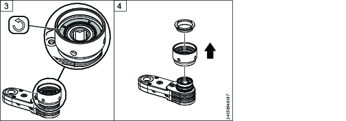
Remove the bearing housing and the snap ring, shim ring and needle carrier.
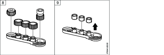
Remove the output gear, middle gears and input gears.

Note the direction of the output gear (hexagonal shape up or down). It should be placed in the same way when assembling the GFA module.
Remove the needle rollers.
Depending on the GFA model the needle rollers can be loose or assembled in bearing rings.


Dismantling the GFA Module with Shaft lid generation 2
The instruction below shows an example of a GFA module. Details may vary depending on the GFA model.
For service tool, see Service Equipment for the specific GFA model.
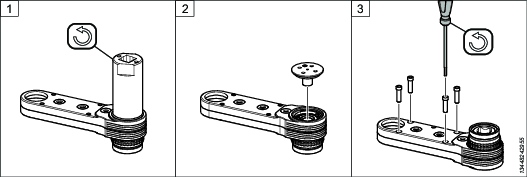
Loosen the screws securing the shaft lid plate.
Remove the shaft lid plate.
Remove the shaft lid.
Loosen the screws securing the upper housing. The number and type of screws depend on the GFA model.
Place the GFA module on a rubber mat. Hit the shafts to loosen the upper and lower part of the housing.
Separate the housings.
Remove the bearing housing and the snap ring, shim ring and needle carrier.
Remove the output gear, middle gears and input gears.
Note the direction of the output gear (hexagonal shape up or down). It should be placed in the same way when assembling the GFA module.
Remove the needle rollers.
Depending on the GFA model the needle rollers can be loose or assembled in bearing rings.
Dismantling COT250 GFA Module with Shaft lid generation 2
For service tool, see Service Equipment for the specific GFA model.
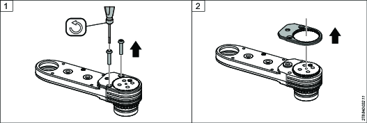
Loosen the screws securing the shaft lid plate.
Remove the shaft lid plate.
Remove the shaft lid.
Loosen the screws and remove spacer and nut securing the upper housing. The number and type of screws depend on the GFA model.
Place the GFA module on a rubber mat. Hit the shafts to loosen the upper and lower part of the housing.
Separate the housings.
Remove the bearing housing and the cove ring, index spring, quick index ring and spring ring.
Remove the output gear, middle gears and input gears.
Note the direction of the output gear (hexagonal shape up or down). It should be placed in the same way when assembling the GFA module.
Remove the needle rollers.
Depending on the GFA model the needle rollers can be loose or assembled in bearing rings.


Removing a Fixed Index Adapter Generation 1 and 2
For service tool, see Service Equipment for the specific GFA model.
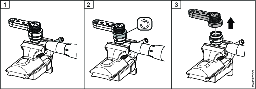
Fasten the drive unit, together with the GFA system, in a vice.
Loosen the nut from the adapter using a C-spanner.
Remove the GFA unit from the adapter.
Loosen the adapter with a C-spanner to remove it from the drive unit.
The adapter is fixed to the drive unit with Loctite. Loosening the tool from the adapter requires strong force. It is recommended to use a heat gun to facilitate the loosening.
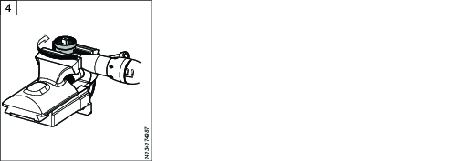
Removing a Fork Adapter
For service tool, see Service Equipment for the specific GFA model.
Fasten the drive unit in a vice and loosen the nut, using a C-spanner.
Remove the GFA module.
Loosen and remove the adapter from the fork adapter, using a C-spanner.
The adapter is fixed with Loctite. Loosening the adapter requires strong force. It is recommended to use a heat gun to facilitate the loosening.
Loosen and remove the bearing shell adapter from the fork adapter, using a C-spanner.
The bearing shell is fixed with Loctite. Loosening the bearing shell requires strong force. It is recommended to use a heat gun to facilitate the loosening.
Remove the fork adapter from the angle head.
If applicable, fasten the tool's bearing shell to the angle head. Note: this is not the same bearing shell as the one for the adapter, in Step 4.
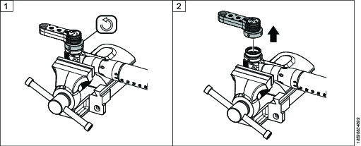
Removing a Quick Index Adapter Generation 1 and 2
For service tool, see Service Equipment for the specific GFA model.
Fasten the drive unit together with the GFA system, in a vice. Use a C-spanner to loosen the adapter from the drive unit.
The adapter is fixed to the drive unit with Loctite. Loosening the adapter from the drive unit requires strong force. It is recommended to use a heat gun to facilitate the loosening.
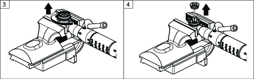
Remove the adapter from the drive unit.
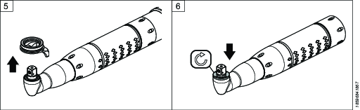
Loosen the ring inside the adapter.
Remove the ring and the adapter from the GFA unit.