Assembling Instructions
Assembling the GFA Module with Shaft Lid generation 1
For service tool, see Service Equipment for the specific GFA model.
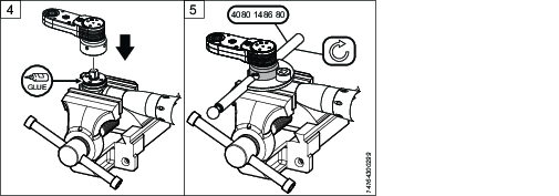
Depending on the type of needle bearings, assembled with needle carrier (A) or loose pins (B), do the following:
A) Add grease to the needle carrier. Put the needle carrier over the shafts.
B) Add grease to the middle gears. Put the middle gears over the shafts.
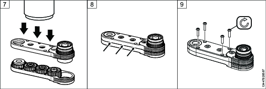
Depending on the type of needle bearings, assembled with needle carrier (A) or loose pins (B), do the following:
A) Add grease to the middle gears. Put the middle gears over the needle carriers.
B) Add grease to the needles. Insert the loose needles between the shafts and the middle gears. Make sure all the needles go in - there should be no gaps.
Add grease to the output gear. Place the output gear in the housing. Position the gear with the same orientation (hexagonal shape pointing up or down), as when dismantling.
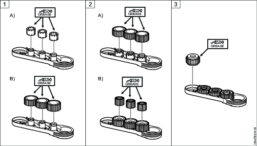
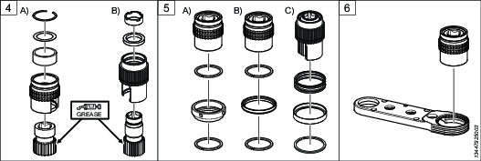
Add grease to the input gear. Insert the input gear into the bearing housing and put back the snap ring, shim ring and needle carrier (if they were removed):
A) GFA system with fixed index or quick index adapter generation 1.
B) GFA system with fixed index or quick index adapter generation 2.
Depending on the adapter type the bearing house can be prepared in one of the following ways, before inserted into the GFA housing:
A) GFA system with fixed index adapter generation 1:
Insert the bearing housing into the upper locking ring, nut, and lower locking ring.B) GFA system with quick index adapter generation 1:
Insert the bearing housing into the upper locking ring, guide ring, and lower locking ring.C) GFA system with fixed index or quick index adapter generation 2:
Insert the bearing housing into the upper locking ring, guide ring, and lower locking ring.

Locking rings are not used in all GFA models, refer to the spare parts list of the GFA model in question.
Insert the bearing housing, prepared as in the step above, into the GFA module housing.
The bearing housing can be inserted from the top or from below, depending on the GFA model.
Use a press tool to press the upper and lower parts of the housing together.
It is important to press evenly over the housing.
Make sure there is no gap between the upper and lower part of the housing.
Tighten the screws to the specified torque. The number and type of screws depend on the GFA model.
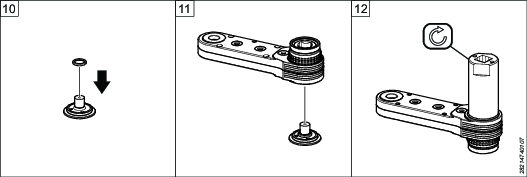
If applicable, put the bearing support washer over the shaft lid. The bearing support is not available of all GFA models.
Insert the shaft lid into the housing.
Turn the GFA upside down, put it in a vice and tighten the shaft lid.
Assembling the GFA Module with Shaft Lid generation 2
For service tool, see Service Equipment for the specific GFA model.
Depending on the type of needle bearings, assembled with needle carrier (A) or loose pins (B), do the following:
A) Add grease to the needle carrier. Put the needle carrier over the shafts.
B) Add grease to the middle gears. Put the middle gears over the shafts.
Depending on the type of needle bearings, assembled with needle carrier (A) or loose pins (B), do the following:
A) Add grease to the middle gears. Put the middle gears over the needle carriers.
B) Add grease to the needles. Insert the loose needles between the shafts and the middle gears. Make sure all the needles go in - there should be no gaps.
Add grease to the output gear. Place the output gear in the housing. Position the gear with the same orientation (hexagonal shape pointing up or down), as when dismantling.
Add grease to the input gear. Insert the input gear into the bearing housing and put back the snap ring, shim ring and needle carrier (if they were removed):
A) GFA system with fixed index or quick index adapter generation 1.
B) GFA system with fixed index or quick index adapter generation 2.
Depending on the adapter type the bearing house can be prepared in one of the following ways, before inserted into the GFA housing:
A) GFA system with fixed index adapter generation 1:
Insert the bearing housing into the upper locking ring, nut, and lower locking ring.B) GFA system with quick index adapter generation 1:
Insert the bearing housing into the upper locking ring, guide ring, and lower locking ring.C) GFA system with fixed index or quick index adapter generation 2:
Insert the bearing housing into the upper locking ring, guide ring, and lower locking ring.
Locking rings are not used in all GFA models, refer to the spare parts list of the GFA model in question.
Insert the bearing housing, prepared as in the step above, into the GFA module housing.
The bearing housing can be inserted from the top or from below, depending on the GFA model.
Use a press tool to press the upper and lower parts of the housing together.
It is important to press evenly over the housing.
Make sure there is no gap between the upper and lower part of the housing.
Tighten the screws securing the upper housing to the specified torque. The number and type of screws depend on the GFA model.
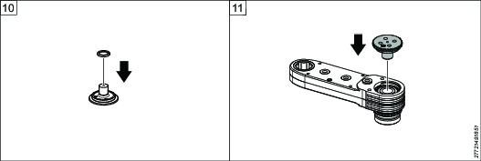
If applicable, put the bearing support washer over the shaft lid. The bearing support is not available for all GFA models.
Turn the GFA module upside down. Insert the shaft lid into the housing. In the case that the GFA module has keys, check that the keys are in the correct position.
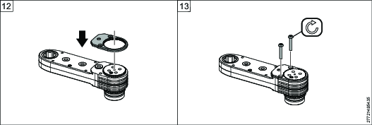
Put the shaft lid plate onto the shaft lid, the shaft lid should fit into the hole in the middle. Use a pin spanner to make sure that the shaft lid plate is in the correct position.
Tighten the screws securing the shaft lid plate to the specified torque.
Assemble COT250 GFA Module with Shaft lid generation 2
Apply grease to needle carrier and assemble the needle carrier over the shafts.
Apply grease to middle gears and assemble the middle gears over the needle carriers.
Add grease to the output gear. Place the output gear in the housing. Position the gear with the same orientation (hexagonal shape pointing up or down), as when dismantling.
Add grease to the input gear. Insert the input gear into the bearing housing and put back needle carrier (if they were removed):
A) GFA system with fixed index or quick index adapter generation 1.
B) GFA system with fixed index or quick index adapter generation 2.
Depending on the adapter type the bearing house can be prepared in one of the following ways, before inserted into the GFA housing:
GFA system with fixed index or quick index adapter generation 2:
Insert the bearing housing into the cover ring, index spring, quick index ring and spring ring.
Locking rings are not used in all GFA models, refer to the spare parts list of the GFA model in question.
Insert the bearing housing, prepared as in the step above, into the GFA module housing.
The bearing housing can be inserted from the top or from below, depending on the GFA model.
Use a press tool to press the upper and lower parts of the housing together.
It is important to press evenly over the housing.
Make sure there is no gap between the upper and lower part of the housing.
Tighten the housing with the help of screws, spacer and nut securing the upper housing to the specified torque. The number and type of screws depend on the GFA model.
If applicable, put the bearing support washer over the shaft lid. The bearing support is not available for all GFA models.
Turn the GFA module upside down. Insert the shaft lid into the housing. In the case that the GFA module has keys, check that the keys are in the correct position.
Put the shaft lid plate onto the shaft lid, the shaft lid should fit into the hole in the middle. Use a pin spanner to make sure that the shaft lid plate is in the correct position.
Tighten the screws securing the shaft lid plate to the specified torque.


Attaching a Fixed Index Adapter Generation 1 and 2
For service tool, see Service Equipment for the specific GFA model.
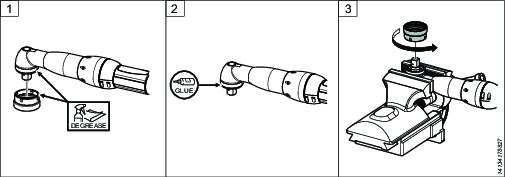
Clean the threads of the drive unit and the adapter.
Apply Loctite 2701, or similar, to the threads of the drive unit.
Fasten the drive unit in a vice and tighten the adapter to specified torque.
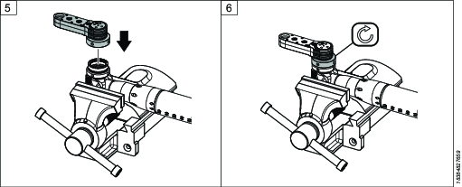
Attach the adapter to the nut.
Tighten the nut with a C-spanner to specified torque.
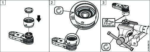
Attaching a Fork Adapter
For service tool, see Service Equipment for the specific GFA model.
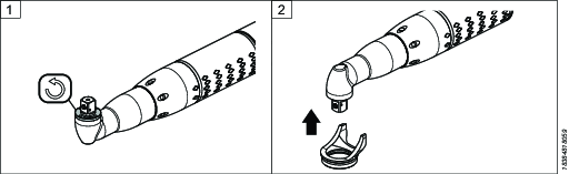
Remove the bearing shell from the angle head of the tool.
Attach the fork adapter to the angle head.
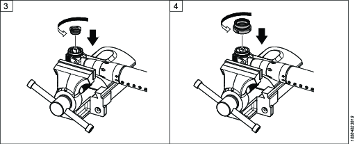
Fasten the tool to a vice. Clean the threads. Apply Loctite 2701, or similar, to the bearing shell adapter, push it into the fork adapter and tighten to specified torque. Note: this is not the same bearing shell as the one for the angle head, in Step 1.
Clean the threads. Apply Loctite 2701, or similar, to the threads of the adapter. Screw it onto the fork adapter and tighten to specified torque, using a C-spanner.
Attach the nut with the GFA module to the adapter of the drive unit.
Tighten the nut, using a C-spanner.
Attaching a Quick Index Adapter Generation 1 and 2
For service tool, see Service Equipment for the specific GFA model.
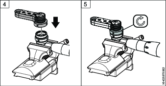
Attach the adapter and ring to the GFA unit.
Make sure the spring is inserted in the adapter before attaching the ring.
Tighten the ring inside the adapter to specified torque.
Fasten the drive unit to a vice. Clean the threads of the drive unit and the adapter.
Apply Loctite 2701, or similar, to the threads of the drive unit.
Attach the adapter to the drive unit and use a C-spanner to tighten the adapter to specified torque.