IRC-Connect
Data analyzer
Product Information
General Information
Safety Signal Words
The safety signal words Danger, Warning, Caution, and Notice have the following meanings:
DANGER | DANGER indicates a hazardous situation which, if not avoided, will result in death or serious injury. |
WARNING | WARNING indicates a hazardous situation which, if not avoided, could result in death or serious injury. |
CAUTION | CAUTION, used with the safety alert symbol, indicates a hazardous situation which, if not avoided, could result in minor or moderate injury. |
NOTICE | NOTICE is used to address practices not related to personal injury. |
Warranty
Product warranty will expire 12+1 months after dispatch from Atlas Copco's Distribution Center.
Normal wear and tear on parts is not included within the warranty.
Normal wear and tear is that which requires a part change or other adjustment/overhaul during standard tools maintenance typical for that period (expressed in time, operation hours or otherwise).
The product warranty relies on the correct use, maintenance, and repair of the tool and its component parts.
Damage to parts that occurs as a result of inadequate maintenance or performed by parties other than Atlas Copco or their Certified Service Partners during the warranty period is not covered by the warranty.
To avoid damage or destruction of tool parts, service the tool according to the recommended maintenance schedules and follow the correct instructions.
Warranty repairs are only performed in Atlas Copco workshops or by Certified Service Partners.
Atlas Copco offers extended warranty and state of the art preventive maintenance through its ToolCover contracts. For further information contact your local Service representative.
For electrical motors:
Warranty will only apply when the electric motor has not been opened.
Website
Information concerning our Products, Accessories, Spare Parts and Published Matters can be found on the Atlas Copco website.
Please visit: www.atlascopco.com.
ServAid
ServAid is a portal that is continuously updated and contains Technical Information, such as:
Regulatory and Safety Information
Technical Data
Installation, Operation and Service Instructions
Spare Parts Lists
Accessories
Dimensional Drawings
Please visit: https://servaid.atlascopco.com.
For further Technical Information, please contact your local Atlas Copco representative.
Country of Origin
For the Country of Origin, please refer to the information on the product label.
Dimensional Drawings
Dimensional Drawings can be found either in the Dimensional Drawings Archive, or on ServAid.
Please visit: http://webbox.atlascopco.com/webbox/dimdrw or https://servaid.atlascopco.com.
Overview
Applications
The IRC-Connect is designed to enable the wireless communication between a torque or torque/angle transducer and a remote device. After acquiring test results data from the transducer, the IRC-Connect communicates it wirelessly to the remote device.
The remote devices that communicate with the IRC-Connect are:
STa 6000 / STa 6000 Plus;
STpad;
STpalm.
For further information about the remote device's configuration and operations with the IRC-Connect, respectively refer to STa 6000 / Sta 6000 Plus User Guide, STpad Configuration Manual and STpalm Configuration Manual.
Tool overview
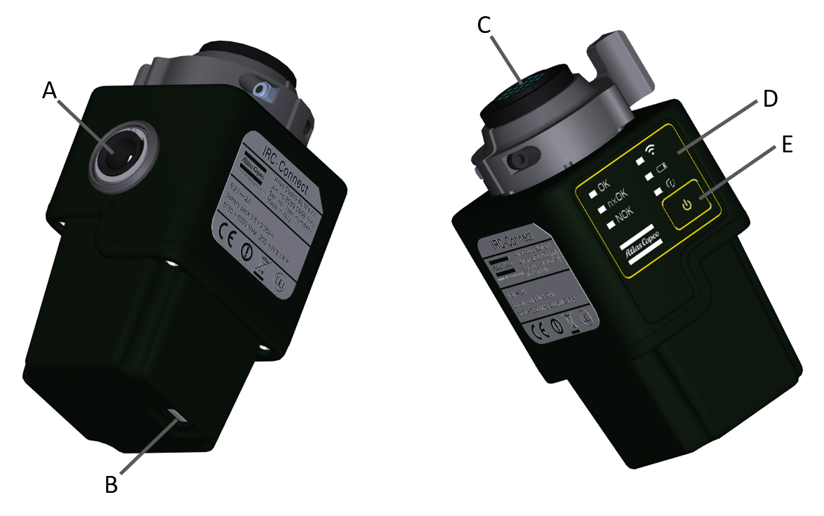
A | External power supply connector | B | USB port |
C | Connector for transducer | D | LED system |
E | Power switch / Remote pairing / Firmware upgrade button | ||
Radio module characteristics
IRC-B
Output frequency | 2.402 - 2.480 GHz, ISM band |
Maximum conducted output power | 11 dBm |
Maximum radiated output power | 14 dBm EIRP (including maximum antenna gain 3 dBi) |
Receiver conducted sensitivity | -90 dBm |
Environmental conditions
Indoor use only | |
Altitude | Up to 2000 m |
Ambient temperature range | +5 to +40 °C |
Maximum relative humidity 80 % for temperatures up to 31 °C decreasing linearly to 50 % relative humidity at 40 °C |
|
Environmental class | II |
Pollution degree | 2 |
Dimensions and weight
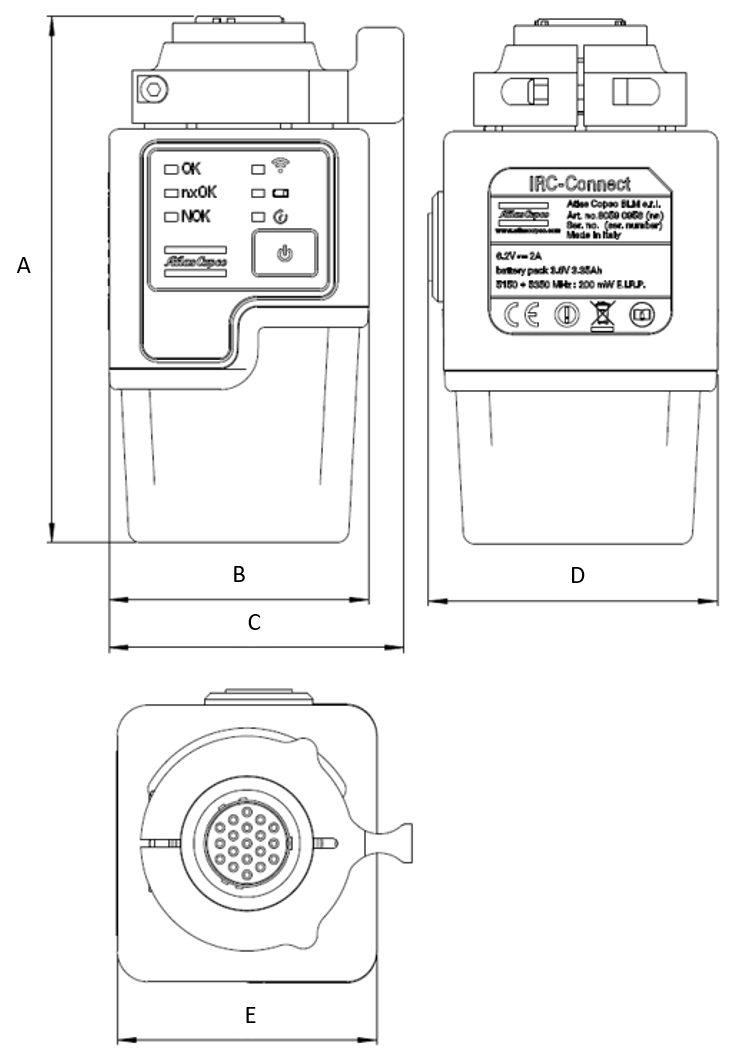
A | B | C | D | E | Weight |
|---|---|---|---|---|---|
110.1 | 55 | 62.5 | 61.3 | 55 | 360 |
Supported transducers
IRTT-B
Torque only models
Model | Capacity [Nm] | Drive | Ordering N. |
|---|---|---|---|
5-I06 | 5 | ¼” hex | 8059 0942 05 |
5-06 | 5 | ¼” square | 8059 0942 07 |
20-I06 | 20 | ¼” hex | 8059 0942 10 |
20-06 | 20 | ¼” square | 8059 0942 15 |
25-10 | 25 | 3/8” square | 8059 0942 20 |
75-10 | 75 | 3/8” square | 8059 0942 25 |
180-13 | 180 | ½” square | 8059 0942 30 |
500-20 | 500 | ¾” square | 8059 0942 35 |
750-25 | 750 | 1” square | 8059 0942 40 |
1400-25 | 1400 | 1” square | 8059 0942 45 |
3000-38 | 3000 | 1 ½” square | 8059 0942 52 |
5000-38 | 5000 | 1 ½” square | 8059 0942 56 |
Torque and Angle models
Models | Capacity [Nm] | Pulses per revolution [*] | Drive | Ordering N. |
|---|---|---|---|---|
1A-I06 | 1 | 256/1024 | ¼” hex | 8059 0943 96 |
2A-I06 | 2 | 256/1024 | ¼” hex | 8059 0943 01 |
5A-I06 | 5 | 256/1024 | ¼” hex | 8059 0943 06 |
5A-06 | 5 | 256/1024 | ¼” square | 8059 0943 08 |
20A-I06 | 20 | 256/1024 | ¼” hex | 8059 0943 11 |
20A-06 | 20 | 256/1024 | ¼” square | 8059 0943 16 |
25A-10 | 25 | 256/1024 | 3/8” square | 8059 0943 21 |
75A-10 | 75 | 256/1024 | 3/8” square | 8059 0943 26 |
180A-13 | 180 | 256/1024 | ½” square | 8059 0943 31 |
500A-20 | 500 | 256/1024 | ¾” square | 8059 0943 36 |
750A-25 | 750 | 256/1024 | 1” square | 8059 0943 41 |
1400A-25 | 1400 | 256/1024 | 1” square | 8059 0943 46 |
3000A-38 | 3000 | 384/1536 | 1 ½” square | 8059 0943 52 |
5000A-38 | 5000 | 384/1536 | 1 ½” square | 8059 0943 56 |
10000A-38 | 10000 | 512/2048 | 1 ½” square | 8059 0943 60 |
SRTT-B
Model | Capacity [Nm] | Drive | Ordering N. |
|---|---|---|---|
SRTT-B 0.5 – 13 | 0.5 | ½” square | 8059 0946 03 |
SRTT-B 2 – 13 | 2 | ½” square | 8059 0946 09 |
SRTT-B 5 – 13 | 5 | ½” square | 8059 0946 15 |
SRTT-B 10 – 13 | 10 | ½” square | 8059 0946 21 |
SRTT-B 25 – 36 | 25 | 36mm hex | 8059 0946 28 |
SRTT-B 50 – 36 | 50 | 36mm hex | 8059 0946 36 |
SRTT-B 100 – 36 | 100 | 36mm hex | 8059 0946 45 |
SRTT-B 250 – 36 | 250 | 36mm hex | 8059 0946 54 |
SRTT-B 500 – 50 | 500 | 50mm hex | 8059 0946 63 |
SRTT-B 1000 – 50 | 1000 | 50mm hex | 8059 0946 75 |
SRTT-B 2000 – 50 | 2000 | 50mm hex | 8059 0946 84 |
QRTT-B
Model | Capacity [Nm] | Drive | Ordering N. |
|---|---|---|---|
20A-10 | 20 | 3/8” square | 8059 0947 13 |
75A-10 | 75 | 3/8” square | 8059 0947 18 |
200A-13 | 200 | ½” square | 8059 0947 23 |
500A-20 | 500 | ¾” square | 8059 0947 28 |
1000A-25 | 1000 | 1” square | 8059 0947 33 |
Technical Product Data
Technical Product Data can be found on either ServAid, or the Atlas Copco website.
Please visit: https://servaid.atlascopco.com or www.atlascopco.com.
Accessories
Accessories Included
External Power Supply
The external power supply is used to recharge the IRC-Connect internal battery.
The IRC-Connect can be operated as usual when the battery is under charge.
Input: 100-240 V~ 50/60 Hz, 0.6 A
Output: 5.95 V
 3 A, 18 W
Overvoltage category: II
Battery
It is highly recommended a full battery charge before the first use of the IRC-Connect.
In order to stabilize the battery run time, it is recommended to perform a complete charge-discharge-recharge cycle.
Rechargeable Li-ion battery, 3.6 V 3.35 Ah and/or 6.2 V
 2 A
2 ABattery life:
6 hours (standalone usage)
5 hours (continued communication usage)
Charging time: maximum 4 hours
Interfaces
Power Switch
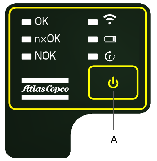
A | Power Switch |
Through the Power Switch, the user can:
Switch the IRC-Connect on and off. Press once to switch the tool on; keep pressed for three seconds to switch the tool off.
Pair the IRC-Connect with a remote device. For further information, refer to Pairing the IRC-Connect with a Remote Device.
Upgrade the IRC-Connect Firmware. For further information, refer to Manual Firmware upgrade.
LED system
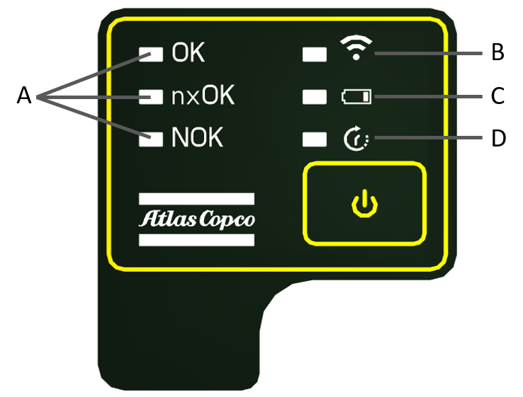
A | Results LEDs | B | Radio LED |
C | Battery LED | D | Measurement LED |
Radio LED
Behavior | Description |
|---|---|
Steady ON blue | Pairing procedure with remote device on going. |
Blinking blue | IRC communication active. |
Results LEDs
Signaling LED | Behavior* | Strategy | Description |
|---|---|---|---|
OK LED | Steady ON green | Tool test | Single test result OK. |
nxOK LED | 1 long blink yellow + 1 long pause | - | The date/hour is not set. Connect the IRC-Connect either to an STa 6000/STa 6000 Plus, to ToolsTalk BLM software or to QAT Calibrator software to synchronize date and hour. Do not make any measurement with the IRC-Connect. |
nxOK LED | Steady ON yellow | Tool test | Batch of tests completed with OK results. |
NOK LED | Steady ON red | Tool test | Single test result NOK. |
NOK LED | 1 long blink red + 1 long pause | All | The transducer has been overloaded. Reboot the IRC connect to double-check the Zero. |
NOK LED | 1 short blink red + 1 short pause | All | Transducer Zero Torque error, or Gyroscope Zero error. Reboot the IRC connect to double-check the Zero. |
NOK LED | 2 short blinks red + 1 long pause | All | At least one Pset parameter is not compatible with the transducer minimum load, or at least one Pset parameter is not compatible with the transducer capacity. |
NOK LED | 3 short blinks red + 1 long pause | All | The transducer connected to the IRC-Connect is not compatible with the Pset. |
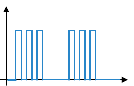
*Meaning of the main LED behaviors:
Steady ON | 1 short blink + 1 long pause | 1 long blink + 1 long pause | 2 short blinks + 1 long pause | 3 short blinks + 1 long pause |
 |  |  |  |  |
Measurement LED
Behavior | Description |
|---|---|
Steady ON red | The IRC-Connect is powering on. |
Blinking red | Measurement on going. |
Battery LED
Behavior | Description |
|---|---|
Steady green | Battery charge over 50%. |
Steady yellow | Battery charge between 25% and 50%. |
Steady red | Battery charge between 10% and 25%. |
Blinking red | Battery charge below 10%. |
Blinking green | Battery under charge (charge level below 95%). |
Connector for transducers
The IRC-Connect has a female 19-pole connector for the transducer connection.
USB port
The USB port is used to upgrade the IRC-Connect firmware (for further information, refer to Manual Firmware Upgrade).
When connecting the IRC-Connect with the PC of the user, it is mandatory to connect the USB cable either to USB1 port or to USB2 port.
Installation
Installation Instructions
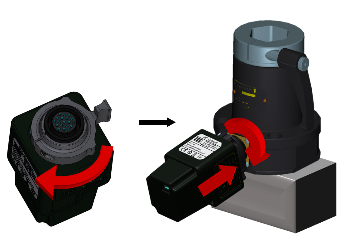
Connecting the SRTT-B to the IRC-Connect
In order to facilitate the operation, the SRTT-B must be placed on a raised support during the connection with the IRC-Connect, as shown in the picture below.
Rotate the IRC-Connect connector lever counter-clockwise (towards the Unlock position).
Connect the SRTT-B to the external connector of the IRC-Connect.

Make sure to align the transducer's pins with their respective housings on the IRC-Connect's connector.
Rotate the IRC-Connect connector lever clockwise to fasten the tool to the transducer.
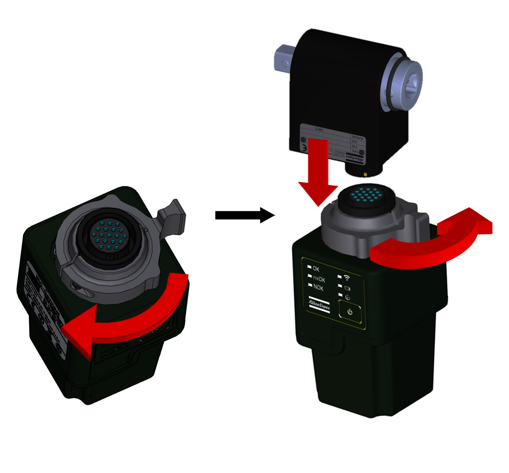
Connecting the IRTT-B / QRTT-B to the IRC-Connect
Rotate the IRC-Connect connector lever counter-clockwise (towards the Unlock position).
Connect the IRTT-B / QRTT-B to the external connector of the IRC-Connect.

Make sure to align the transducer's pins with their respective housings on the IRC-Connect's connector.
Rotate the IRC-Connect connector lever clockwise to fasten the transducer to the tool.
Operation
Ergonomic Guidelines
Consider your workstation as you read through this list of general ergonomic guidelines to identify areas for improvement in posture, component placement, or work environment.
Take frequent breaks and change work positions frequently.
Adapt the workstation area to your needs and the work task.
Adjust for a convenient reach range by determining where parts and tools need to be located to avoid static load.
Use workstation equipment such as tables and chairs appropriate for the work task.
Avoid work positions above shoulder level or with static holding during assembly operations.
When working above shoulder level, reduce the load on the static muscles by lowering the weight of the tool, using for example torque arms, hose reels or weight balancers. You can also reduce the load on the static muscles by holding the tool close to the body.
Take frequent breaks.
Avoid extreme arm or wrist postures, particularly during operations requiring a degree of force.
Adjust for a convenient field of vision that requires minimal eye and head movements.
Use appropriate lighting for the work task.
Select the appropriate tool for the work task.
In noisy environments, use ear protection equipment.
Use high-quality inserted tools and consumables to minimize exposure to excessive levels of vibration.
Minimize exposure to reaction forces.
When cutting:
A cut-off wheel can get stuck if the cut-off wheel is bent or not guided properly. Use the correct flange for the cut-off wheel and avoid bending the cut-off wheel during operation.
When drilling:
The drill might stall when the drill bit breaks through. Use support handles if the stall torque is high. The safety standard ISO11148 part 3 recommends using a device to absorb a reaction torque above 10 Nm for pistol grip tools and 4 Nm for straight tools.
When using direct-driven screwdrivers or nutrunners:
Reaction forces depend on the tool settings and joint characteristics. Strength and posture determine the amount of reaction force that an operator can tolerate. Adapt the torque setting to the operator's strength and posture and use a torque arm or reaction bar if the torque is too high.
In dusty environments, use a dust extraction system or wear a mouth protection mask.
Configuration Instructions
Pairing the IRC-Connect with a remote device
In order to connect the IRC-Connect to a remote device, tool and device must first be associated through a pairing procedure.
The pairing procedure is required only once before the first connection to a remote device: once the IRC-Connect is paired to the remote device, the user can directly connect them in every moment.
To pair the IRC-Connect with a remote device, do the following:
Switch both the remote device and the IRC-Connect on.
Set the remote device up in order to enable the IRC-Connect connection. For further information refer to the User Guide specific to the remote device in use.
On the IRC-Connect main panel:
press the power switch three times, if you are pairing the tool with an STa 6000 / STa 6000 Plus.
press the power switch five times, if you are pairing the tool with an STpad.

The reference STpad firmware version is 07.02a and later.
press the power switch five times, if you are pairing the tool with an STpalm.

During the pairing procedure, the Radio LED is steady on, while the Results LEDs blinks together.
Start the pairing procedure on the remote device.
For further information, respectively refer to STa 6000/STa 6000 Plus User Guide, STpad Configuration Manual and STpalm Configuration Manual.
Operating Instructions
Working with the IRC-Connect
The IRC-Connect operation workflow depends on the remote device connected to the tool.
For a detailed explanation on how to work with the IRC-Connect, refer to the User Guide specific to the remote device in use.
General workflow:
The remote device sends a Pset (Parameter set) to the IRC-Connect to run the test.
The IRC-Connect Measurement LED starts blinking.
The test(s) is performed.
The IRC-Connect sends each test result (and trace where applicable) to the remote device.
If the IRC-Connect gets disconnected from the remote device, the results of the test are stored in the IRC-Connect memory. Once the IRC-Connect is reconnected, the results/traces are sent to the remote device.
During the test/tightening operation, the Result LEDs on the IRC-Connect behave accordingly both to test results and to potential error conditions. for further information, refer to LED system.
For further information, refer to STa 6000/STa 6000 Plus User Guide, STpad Configuration Manual, STpalm Configuration Manual.
Working with ToolsTalk BLM
For information on how to work with the IRC-Connect using ToolsTalk BLM, refer to the IRC-Connect Configuration Manual.
Service
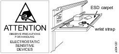
Preventing ESD Problems
The components inside the product and controller are sensitive to electrostatic discharge. To avoid future malfunction, make sure that service and maintenance is carried out in an ESD approved work environment. The figure below shows an example of an appropriate service work station.
Maintenance Instructions
Calibration
The tool must be calibrated at least once a year.
Contact Atlas Copco Service Personnel for the tool calibration.
Overhaul
Have the tool serviced by a qualified repair person using only identical replacement parts. This will ensure that the safety of the tool is maintained.
Service must only be carried out by qualified personnel who have been trained for service on this tool.
Service Recommendations
Preventive maintenance is recommended at regular intervals. See the detailed information on preventive maintenance. If the product is not working properly, take it out of service and inspect it.
If no detailed information about preventive maintenance is included, follow these general guidelines:
Clean appropriate parts accurately
Replace any defective or worn parts
Troubleshooting
Troubleshooting quick guide
If a problem occurs, before taking any action (i.e. replacing parts or contacting customer support) verify first that the IRC-Connect is being used properly; improper operation can cause failures even if the system is in good working order.
Problem | Possible causes | Solution |
|---|---|---|
The IRC-Connect does not connect to the STa 6000 / STa 6000 Plus | Pairing procedure not performed yet. | Ensure that the pairing procedure is performed. Then, connect the IRC-Connect to the STa 6000 / Sta 6000 Plus. |
Connection not enabled. | Ensure that the IRC-Connect connection is enabled on the STa 6000. | |
STa 6000 / STa 6000 Plus without IRC-W module, or module installed in the wrong slot. | Ensure that the IRC-W module is properly installed into the STa 6000. | |
The IRC-Connect is placed too far from the STa 6000 / STa 6000 Plus. | Switch off and on both the STa 6000 and the IRC-Connect leaving them on the same desk and verify that the connection becomes active. | |
The pairing procedure ends unsuccessfully. | Error occurred during the procedure. | Repeat the pairing procedure. |
Unable to connect the IRC-Connect to ToolsTalk BLM. | Drivers not correctly installed. | On the PC, open Control Panel > Device manager and uninstall the drivers. Reinstall ToolsTalk BLM making sure that the IRC-Connect is not connected via USB to the PC. |
Recycling
Environmental Regulations
When a product has served its purpose it has to be recycled properly. Dismantle the product and recycle the components in accordance with local legislation.
Batteries shall be taken care of by your national battery recovery organization.