STRwrench Controller Compact
Modular Electronic Wrench
Product Information
General Information
Safety Signal Words
The safety signal words Danger, Warning, Caution, and Notice have the following meanings:
DANGER | DANGER indicates a hazardous situation which, if not avoided, will result in death or serious injury. |
WARNING | WARNING indicates a hazardous situation which, if not avoided, could result in death or serious injury. |
CAUTION | CAUTION, used with the safety alert symbol, indicates a hazardous situation which, if not avoided, could result in minor or moderate injury. |
NOTICE | NOTICE is used to address practices not related to personal injury. |
Warranty
Product warranty will expire 12+1 months after dispatch from Atlas Copco's Distribution Center.
Normal wear and tear on parts is not included within the warranty.
Normal wear and tear is that which requires a part change or other adjustment/overhaul during standard tools maintenance typical for that period (expressed in time, operation hours or otherwise).
The product warranty relies on the correct use, maintenance, and repair of the tool and its component parts.
Damage to parts that occurs as a result of inadequate maintenance or performed by parties other than Atlas Copco or their Certified Service Partners during the warranty period is not covered by the warranty.
To avoid damage or destruction of tool parts, service the tool according to the recommended maintenance schedules and follow the correct instructions.
Warranty repairs are only performed in Atlas Copco workshops or by Certified Service Partners.
Atlas Copco offers extended warranty and state of the art preventive maintenance through its ToolCover contracts. For further information contact your local Service representative.
For electrical motors:
Warranty will only apply when the electric motor has not been opened.
Website
Information concerning our Products, Accessories, Spare Parts and Published Matters can be found on the Atlas Copco website.
Please visit: www.atlascopco.com.
ServAid
ServAid is a portal that is continuously updated and contains Technical Information, such as:
Regulatory and Safety Information
Technical Data
Installation, Operation and Service Instructions
Spare Parts Lists
Accessories
Dimensional Drawings
Please visit: https://servaid.atlascopco.com.
For further Technical Information, please contact your local Atlas Copco representative.
Safety Data Sheets MSDS/SDS
The Safety Data Sheets describe the chemical products sold by Atlas Copco.
Please consult the Atlas Copco website for more information www.atlascopco.com/sds.
Country of Origin
For the Country of Origin, please refer to the information on the product label.
Dimensional Drawings
Dimensional Drawings can be found either in the Dimensional Drawings Archive, or on ServAid.
Please visit: http://webbox.atlascopco.com/webbox/dimdrw or https://servaid.atlascopco.com.
Overview
System functionality
The wrench comprises a controller for configurations of tightening programs, batches and other tool functionality, such as input and output signals.
By connecting the wrench to a PC via USB, or by setting up a wireless connection to the factory network, the controller can be accessed through the STRwrench Web User Interface.
Tool Functionality

Position | Description |
|---|---|
1 | Battery |
2 | Handle |
3 | LED indicators |
4 | EHMI (Display with push buttons) |
5 | NFC |
6 | smartHEAD |
7 | Front LED light |
8 | End-fitting tool RFID TAG reader |
9 | Barcode scanner |
10 | USB-C port |
EHMI Description
The EHMI (Extended Human Machine Interface) is located on the wrench controller and comprises of five push buttons and a graphical display.
The display serves as a tool-integrated interface for the operator, showing a subset of the STRwrench Web User Interface.
The EHMI can be used to choose tightening programs, as well as display tightening results.
EHMI with first keyboard version

Position | Name | Description |
|---|---|---|
1 | Display | Screen showing a subset of the STRwrench Web User Interface. |
2 | ON / OFF button | Physical button for turning on/off the wrench. |
3 | Up button | Physical button for moving on-screen selection up. |
4 | Select button | Physical button for confirming on-screen selection. |
5 | Barcode / Front LED button | Physical button for triggering the barcode scanner and the front LED light. |
6 | Down button | Physical button for moving on-screen selection down. |
EHMI with new keyboard version
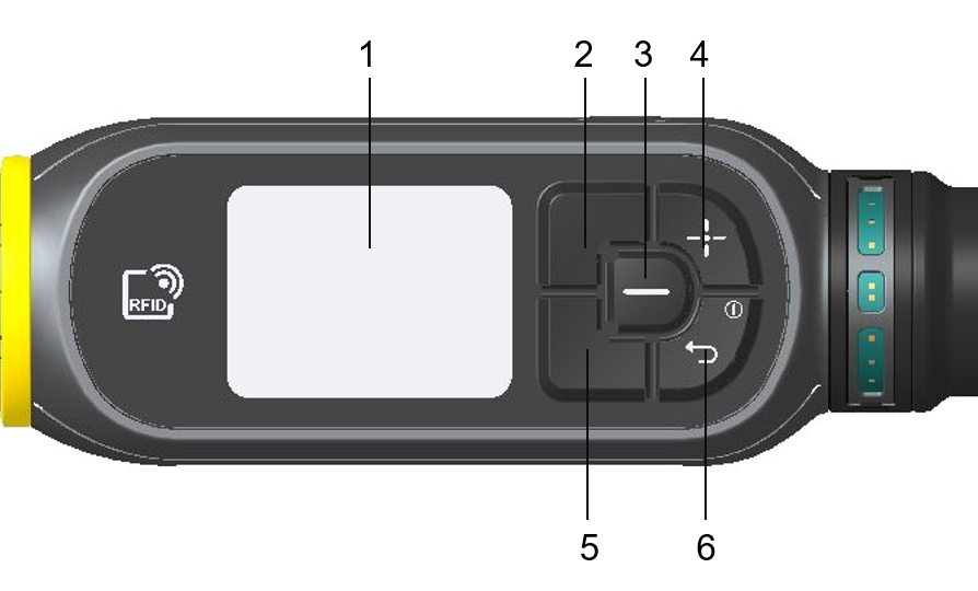
Position | Name | Description |
|---|---|---|
1 | Display | Screen showing a subset of the STRwrench Web User Interface. |
2 | Navigation button (up/left) | Physical button for moving on-screen selection up or left. |
3 | Select button | Physical button for confirming on-screen selection. |
4 | Barcode / Front LED button | Physical button for triggering the barcode scanner and the front LED light. |
5 | Navigation button (down/right) | Physical button for moving on-screen selection down or right. |
6 | on/off button / back button | Physical button for turning on/off the wrench and for moving back from on-screen selection. |
Indicator bar
The indicator bar is presented at the top of all menus. The icons in the indicator bar provide information on the elements listed below.
Icon | Description |
|---|---|
| The wireless connection icon indicates the signal strength of the tool's factory network connection. When no connection is established, the icon is crossed out. |
| The direction icon indicates whether the tightening must be done in clockwise (CW) or counterclockwise (CCW) direction. |
| The battery icon indicates the charge status of the battery attached to the tool. |


The battery charge levels are listed below:
Battery Icon | Icon behavior | Remark |
|---|---|---|
| Steady | Full charge |
| Steady | High charge |
| Steady | Medium charge. Charge battery when possible. |
| Flashing | Low charge. Charge battery. |
| Steady | Critical level, not possible to perform tightening. Charge battery. |


Product data
Operating torque measuring range | from 10 % to 100 % of the smartHEAD capacity |
Torque measurement accuracy (smartHEAD 15 Nm) | 0.5% readout ±1 digit (from 20% to 100% of nominal torque) |
Torque measurement accuracy (smartHEAD 80-1000 Nm) | 0.5 % readout ±1 digit (from 10% to 100% of nominal torque) |
Overload capacity | 120% of smartHEAD capacity |
Temperature stability of torque measurement | 0.1% of capacity/10°C |
Maximum angular speed | 150 °/s |
Angle measurement accuracy | ±1° over 360° without torque preload ±1% over 360° with torque preload |
Weight | 774 g |
Dimensions and weight

Product | L* | K | X | Y | Z | H | Weight | E |
|---|---|---|---|---|---|---|---|---|
STRwrench Controller Compact + smartHEAD 15 Nm | 374 | 437 | 145 | 278 | 13.4 | 356 | 1.42 | 9x12 |
STRwrench Controller Compact + smartHEAD 80 Nm | 374 | 437 | 145 | 278 | 13.4 | 356 | 1.45 | 9x12 |
STRwrench Controller Compact + smartHEAD 250 Nm | 499 | 554 | 262 | 278 | 13.4 | 473 | 2.05 | 14x18 |
STRwrench Controller Compact + smartHEAD 250 Nm Long | 699 | 754 | 462 | 278 | 13.4 | 673 | 2.16 | 14x18 |
STRwrench Controller Compact + smartHEAD 400 Nm | 820 | 874 | 583 | 278 | 13.4 | 795 | 2.80 | 14x18 |
STRwrench Controller Compact + smartHEAD 500 Nm | 825 | 874 | 583 | 278 | 13.4 | 795 | 3.25 | 14x18 |
STRwrench Controller Compact + smartHEAD 600 Nm | 1335 | 1352 | 1061 | 278 | 13.4 | 1272 | 4.63 | 21x26 |
STRwrench Controller Compact + smartHEAD 1000 Nm ALU | 1544 | 1470 | 1178 | 278 | 13.4 | 1390 | 8.43 | Ø28 |
STRwrench Controller Compact + smartHEAD 1000 Nm CAR | 1667 | 1593 | 1301 | 278 | 13.4 | 1513 | 6.36 | Ø28 |
*Dimension L is the standard arm, measured from the center of the handle to the center of the end fitting tool. This information is used to calculate the Torque Correction Coefficient when an extension is used. This dimension is calculated for the standard Atlas Copco end fitting tools used during calibration (L-H); if a different end fitting tool is used, this measure must be recalculated.
Refer to STRwrench Firmware User Guide for more information.
Extension length must be less than half of the wrench length including smartHEAD (L/2). If not, a new calibration is recommended.
Technical Product Data
Technical Product Data can be found on either ServAid, or the Atlas Copco website.
Please visit: https://servaid.atlascopco.com or www.atlascopco.com.
If the Technical Product Data is not available on either website, please contact the local Atlas Copco Customer Center for assistance.
Accessories
Accessory Information
Visit the tool's product page on ServAid for information about compatible accessories.
Installation
Installation Instructions
Connecting to STRwrench Web User Interface
Switch on the wrench and open the USB-C port cover.

Do not remove the cover of the USB-C port completely.
Connect the tool to the USB port of the PC. Open a web browser and type in the address of the STRwrench Web User Interface: 169.254.1.1.

Attaching the Battery
Unscrew the battery cap placed on the wrench handle.
Insert the battery into the wrench handle by aligning it with the nut inside until the mechanic stop.
Screw the battery cap on the wrench handle.

Removing the Battery
Make sure the wrench is OFF before removing the battery to avoid sudden shut down.
Unscrew the battery cap placed on the wrench handle.
Pull the battery out of the wrench handle.
Screw the battery cap on the wrench handle.

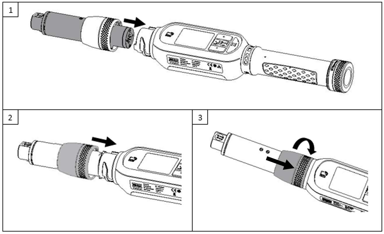
Attaching the smartHEAD
Switch off the wrench. Then, attach the smartHEAD to the wrench controller.
To optimize the vision of the EHMI during operations in special circumstances, the smartHEAD can be attached in 4 positions, each at 90° rotation.
Pull down the ferrule.
Rotate the ferrule clockwise while pushing it down to fasten the smartHEAD to the wrench controller.
Removing the smartHEAD
Push the ferrule down and rotate it counterclockwise to unlock the smartHEAD from the wrench controller.
Pull up the ferrule.
Remove the smartHEAD from the wrench controller.

Attaching the End-Fitting Tool
Insert the End-Fitting Tool by aligning the PIN with the reference guide inside the smartHEAD.
Push the End-Fitting Tool until the mechanic stops and the PIN is locked.
There is only one way to insert the End-Fitting Tool into the smartHEAD. The PIN must be inserted into its housing: do not force it in other positions.

Removing the End-Fitting Tool
Push the PIN on the smartHEAD to unlock it from its housing.
Remove the End-Fitting Tool from the smartHEAD.

Initial Configuration
Tool Configuration
For information about establishing a wireless connection, installing licenses, configuring and assigning tightening programs, refer to STRwrench Firmware User Guide.
Firmware Installation and Upgrade
For information about firmware installation and upgrade, refer to STRwrench Firmware User Guide.
Operation
Ergonomic Guidelines
Consider your workstation as you read through this list of general ergonomic guidelines to identify areas for improvement in posture, component placement, or work environment.
Take frequent breaks and change work positions frequently.
Adapt the workstation area to your needs and the work task.
Adjust for a convenient reach range by determining where parts and tools need to be located to avoid static load.
Use workstation equipment such as tables and chairs appropriate for the work task.
Avoid work positions above shoulder level or with static holding during assembly operations.
When working above shoulder level, reduce the load on the static muscles by lowering the weight of the tool, using for example torque arms, hose reels or weight balancers. You can also reduce the load on the static muscles by holding the tool close to the body.
Take frequent breaks.
Avoid extreme arm or wrist postures, particularly during operations requiring a degree of force.
Adjust for a convenient field of vision that requires minimal eye and head movements.
Use appropriate lighting for the work task.
Select the appropriate tool for the work task.
In noisy environments, use ear protection equipment.
Use high-quality inserted tools and consumables to minimize exposure to excessive levels of vibration.
Minimize exposure to reaction forces.
When cutting:
A cut-off wheel can get stuck if the cut-off wheel is bent or not guided properly. Use the correct flange for the cut-off wheel and avoid bending the cut-off wheel during operation.
When drilling:
The drill might stall when the drill bit breaks through. Use support handles if the stall torque is high. The safety standard ISO11148 part 3 recommends using a device to absorb a reaction torque above 10 Nm for pistol grip tools and 4 Nm for straight tools.
When using direct-driven screwdrivers or nutrunners:
Reaction forces depend on the tool settings and joint characteristics. Strength and posture determine the amount of reaction force that an operator can tolerate. Adapt the torque setting to the operator's strength and posture and use a torque arm or reaction bar if the torque is too high.
In dusty environments, use a dust extraction system or wear a mouth protection mask.
Configuration Instructions
Vibration
This tool is equipped with a vibrating device, which can be configured to signal specific events or warnings.
For more information on the vibration functionality and configuration, refer to STRwrench Firmware User Guide.
smartHEAD illuminating light
The smartHEAD illuminating light provides illumination under the end fitting tool; it can be helpful for a better view of joints in dark areas. It is activated for 10 seconds when the barcode button on the wrench keyboard is pressed.
For more information on the light functionality and configuration, refer to STRwrench Firmware User Guide.
Buzzer
This tool is equipped with a buzzer, which can be configured to signal specific events or warnings.
For more information on the buzzer functionality and configuration, refer to STRwrench Firmware User Guide.
Operating Instructions
Smart Zeroing
An automatic zero adjustment occurs every time the STRwrench is powered on and every time a smartHEAD is connected to the STRwrench controller.
During the zero adjustment, the wrench must lay steady without applying any torque constraint.
If the STRwrench detects any movement during the procedure, the zero adjustment will start over again.
EHMI Operations
Enabling EHMI Operations
To select and run tightening programs, batches and free mode operations through the STRwrench controller EHMI, enable the Keyboard Source option in the Tool Configuration's General Settings of the STRwrench Firmware web user interface.
For more information, refer to STRwrench Firmware User Guide.
When the Keyboard Source is not enabled in the STRwrench Firmware web user interface, the following menus are still available on the controller EHMI:
Info
Tool
Network
Events
Events in the system will generate event dialog boxes in the EHMI display, as well as in the STRwrench Web User Interface. To acknowledge events in the wrench controller, press the Select button once.
Some events are not possible to acknowledge. They will show for three seconds before automatically disappearing from the display.
Tightening
The EHMI can be used to select the tightening program for the device. The selection of a tightening program made on the EHMI overrides whatever task was set for the device in the STRwrench Firmware web user interface. Only tightening programs stored in the device's STRwrench Firmware can be selected from the EHMI.
The Tightening menu is available on the EHMI only if the Keyboard Source option is enabled in the STRwrench Firmware Web User Interface. For more information, refer to STRwrench Firmware User Guide.
Selecting a Tightening Program
Use the Navigation buttons to cycle through the main menu items to the Tightening menu.
Press the Select button to open the Tightening menu.
Use the Navigation buttons to select a tightening program from the list. The number of the currently selected tightening program is marked white.
Press the Select button to confirm.
Reading a Tightening Result

Position | Name | Description |
|---|---|---|
1 | Tightening result | OK result (green). |
2 | Tightening program | Name of the tightening program used. |
3 | Range limit indicator | Up arrow: indicates the final torque is too high. |
4 | Range limit indicator | Up arrow: indicates the final angle is too high. |
5 | Final torque | Torque when the program has concluded. |
6 | Final angle | Angle when the program has concluded. |
Gauge Indicator
On the EHMI, it is possible to set a gauge indicator that provides a visual feedback of the progress of the ongoing tightening. According to the operation's settings, the gauge indicator can display torque reading, angle reading or both.
To enable this feature, set Gauge indicator to On in the Tool Configuration's General Settings of the STRwrench Firmware web user interface. For more information, refer to STRwrench Firmware User Guide.
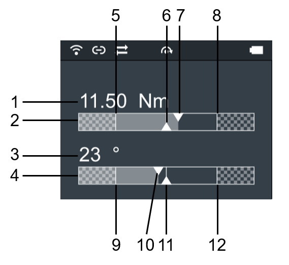
Position | Name | Description |
|---|---|---|
1 | Current torque value | Current numerical value of the ongoing torque reading. |
2 | Torque gauge indicator | Gauge indicator for torque reading. |
3 | Angle value | Current numerical value of the ongoing angle reading. |
4 | Angle gauge indicator | Gauge indicator for angle reading. |
5 | Lower torque limit | Visual display of the lower torque limit value set for the ongoing tightening operation. |
6 | Target torque indicator | Visual display of the target torque value set for the ongoing tightening operation. |
7 | Torque reading indicator | Visual display of the current torque value of the ongoing torque reading. |
8 | Upper torque limit | Visual display of the upper torque limit value set for the ongoing tightening operation. |
9 | Lower angle limit | Visual display of the lower angle limit value set for the ongoing tightening operation. |
10 | Target angle indicator | Visual display of the target angle value set for the ongoing tightening operation. |
11 | Angle reading indicator | Visual display of the current angle value of the ongoing torque reading. |
12 | Upper angle limit | Visual display of the upper torque limit value set for the ongoing tightening operation. |
Batch
Batch sequences are used when operators need to perform a series of tightenings in a single job, and can be restricted to only follow a specific order in which the tightenings are performed. Batch sequences consist of one or more batches, and each batch consists of one or more tightenings.
The EHMI can be used to select the batch sequence for the tool. The selection of a batch sequence made on the EHMI overrides whatever task was set for the tool in the STRwrench Firmware web user interface.
The Batch menu is available on the EHMI only if the Keyboard Source option is enabled in the STRwrench Firmware Web User Interface. For more information, refer to STRwrench Firmware User Guide.
Selecting a Batch Sequence
Use the Navigation buttons to cycle through the main menu items to the Batch menu.
Press the Select button to open the Batch menu.
Use the Navigation buttons to select the batch sequence from the list.
Press the Select button to confirm.
Viewing Tool Information
Use the Navigation buttons to cycle through the main menu items to the Tool menu.
Press the Select button to open the Tool menu.
Use the Navigation buttons to view the tool information.
The Tool menu provides the following information on the smartHEAD:
Tool Information | Description |
|---|---|
Serial no | smartHEAD serial number |
Software version | Software version installed on the tool |
Model | Tool model designation |
Production date | Date when the tool was manufactured |
Ordering number | Product number for ordering the tool |
Max torque | Highest torque output measured by the transducer. |
Number of tightenings | Number of tightenings performed so far |
Calibration date | Date the tool was last calibrated |
Next calibration date | Date when the tool should be calibrated next |
Next calibration date | Date of the next calibration expiration. |
Transducer calibration date (CW) | Date of the last transducer torque calibration in clockwise direction. |
Transducer calibration date (CCW) | Date of the last transducer torque calibration in counterclockwise direction. |
Gyro calibration date (CW) | Date of the last transducer gyro calibration in clockwise direction. |
Gyro calibration date (CCW) | Date of the last transducer gyro calibration in counterclockwise direction. |
Viewing EHMI Information
Use the Navigation buttons to cycle through the main menu items to the Information menu.
Press the Select button to open the Information menu.
Use the Navigation buttons to view the EHMI information.
The Information menu provides the following information on the EHMI:
EHMI Information | Description |
|---|---|
Software version | Controller software installed and date of installation |
Build date | Date when the Controller software was built |
Hardware revision | Revision number of the installed circuit board |
Serial no | Controller serial number |
Language | Display language |
Viewing Network Information
Use the Navigation buttons to cycle through the main menu items to the Network menu.
Press the Select button to open the Network menu.
Use the and Navigation buttons to view the network information.
The Network menu provides the following information about the network the tool is connected to:
Network Information | Description |
|---|---|
Radio type | Type of radio (WLAN) |
Configuration mode | Type of connection (DHCP) |
IP address | IP address of the tool |
Subnet mask | IP address subnet mask |
Channels | Available Wi-Fi channels that can be selected |
Current channel | Channel currently in use |
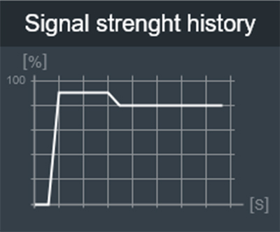
Use the Up- and Down buttons to cycle through the main menu items to the Network menu.
Press the Select button to open the Network menu.
Press the Down button to reach the Signal strength history option, and press the Select button. The graph can be used to detect potential connection blind spots for the tool on a production line.
Free Mode
The Free Mode menu allows running operations without configuring the wrench with specific programs.
When running operations in Free Mode, the results are not stored in the wrench memory and are not transferred to any external controller.
The RFID TAG of the end fitting tool is not read in free mode, meaning that the torque and angle correction coefficients, possibly set for a wrench extension, are not taken into consideration during the operation.
The Free Mode menu is available on the EHMI only if the Keyboard Source option is enabled in the STRwrench Firmware Web User Interface. For more information, refer to STRwrench Firmware User Guide.
Running an Operation in Track Mode
This mode can be used to perform a simple tightening operation while monitoring in real time the applied torque and the angle rotation.
Use the Navigation buttons to cycle through the main menu items to the Free Mode menu.
Press the Select button to open the Free Mode menu.
Press the Select button to start the Track Mode operation.
Apply torque either clockwise (positive torque) or counterclockwise (negative torque): the STRwrench EHMI will display in real time the values of the applied torque and of the angle rotation.
To set the zero point at a given torque value, press the Select button. The zero point is valid only for the current Track Mode operation and not as general reference for all operations performed by the STRwrench.
To exit the track mode operation, press the Back button.
LED indicators Flash Patterns
The standard flash patterns of the LED indicators are shown below:
General description | Light pattern description | Light color | Illustration* |
|---|---|---|---|
Starting up / booting | Pulse light All LEDs | White |
On (left image) - Off (right image) |
Tightening initiation | Spot light Central LED in both front and back view light up. | White |
|
Tightening progress | Radial gradient light, 2 directions LEDs light from the center towards the sides in both front and back view simultaneously. | Green |
|
OK Result | Solid light All LEDs | Green |
|
NOK Result | Alternating light All LEDs | Red |
|
Batch Done | Radial gradient light, 1 direction Starts from central LED in the front view, and continues radially until reaching the central LED. | White |
|


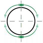

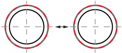

*Illustration description:

A | Light behavior | B | Back |
C | LED ring (section) | D | Front |
Battery charge LED indicators
The wrench is powered by a Lithium-ion battery.
The LED indicators on the battery indicate the State of Charge (SOC) of the battery. To activate the LEDs, press the button placed on the battery.
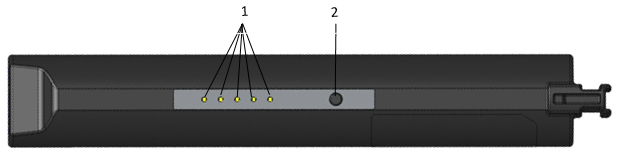
1 | LED indicators | 2 | Button |
The LEDs indicate the remaining capacity of the battery as follows:
Battery charge indicator | Remark |
|---|---|
1 LED | Critical level, not possible to perform tightening. Charge battery. |
2 LEDs | Low charge. Charge battery. |
3 LEDs | Medium charge. Charge battery, when possible. |
4 LEDs | High charge. |
5 LEDs | Full charge. |
Charging the battery
The STRwrench battery has to be charged by means of the STRwrench charger (Article nr. 8059 0924 10).
Automatic Shutdown on Empty Battery
When the battery charge level dips below the critical threshold (12%), the STRwrench is configured to automatically shutdown. As soon as the critical level is reached, the tool starts emitting an intermittent acoustic notification and turns off after 5 minutes.
When the battery charge level is below 12%, it is not possible to perform tightening. When trying to perform tightenings with this charge level, a notification is displayed reminding of the inability to operate.
Service
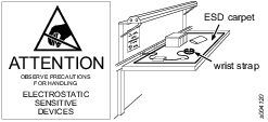
Preventing ESD Problems
The components inside the product and controller are sensitive to electrostatic discharge. To avoid future malfunction, make sure that service and maintenance is carried out in an ESD approved work environment. The figure below shows an example of an appropriate service work station.
Maintenance Instructions
Overhaul
Have the tool serviced by a qualified repair person using only identical replacement parts. This will ensure that the safety of the tool is maintained. Service must only be carried out by qualified personnel who have been trained for service on STRwrench tools.
Tool Calibration
The STRwrench must be calibrated at least once a year. Contact Atlas Copco Service Personnel for the tool calibration.
Service Recommendations
Preventive maintenance is recommended at regular intervals. See the detailed information on preventive maintenance. If the product is not working properly, take it out of service and inspect it.
If no detailed information about preventive maintenance is included, follow these general guidelines:
Clean appropriate parts accurately
Replace any defective or worn parts
smartHEAD Service Recommendations
It is recommended to replace the following smartHEAD components with the frequency specified in the table below:
Component | Frequency |
|---|---|
STR SH Gear | Every 10000 cycles |
STR SH Wave Spring | Every 2000 cycles |
Troubleshooting
Tool connection via USB fails
Cause: the USB cable in use might not support data transmission.
Solution: make sure to use a USB data transfer cable (standard 2.0 or higher).
Events and Error Codes
For a full list of tool event and error codes, refer to STRwrench Firmware User Guide.
Recycling
Environmental Regulations
When a product has served its purpose it has to be recycled properly. Dismantle the product and recycle the components in accordance with local legislation.
Batteries shall be taken care of by your national battery recovery organization.
Recycling Instructions
Wrench controller

Position | Part | Recycle as |
|---|---|---|
1 | Spring & Electronic support | Steel |
2 | Pin support | Polyamide |
3 | Pin connectors | Copper |
4 | PCB supports | Steel |
5 | Display | WEEE |
6 | Display support | Polyamide |
7 | Base PCB | WEEE |
8 | Screws | Steel |
9 | PCB supports | Polyamide |
10 | Radio PCB | WEEE |
11 | Barcode & Coil support | Polyamide |
12 | Screws | Steel |
13 | Controller cover | Polyamide |
14 | Screws | Steel |
15 | Barcode glass support | Glass |
16 | Glass | Glass |
17 | Keyboard | Mixed waste |
18 | Glass | Glass |
19 | Sponge | Foam |
20 | Metal label | Steel |
21 | Coupling | Steel |
22 | Body & ring | Aluminum |
23 | Vibro support | Polyamide |
24 | Vibro | WEEE |
25 | Screws | Steel |
26 | Hole closure | Polyamide |
27 | LED ring cover | Steel |
28 | LED overlay | Polyamide |
29 | LED label fixture | Polyamide |
30 | LED PCB | WEEE |
31 | Foam tape | Foam |
32 | LED suspension ring | Polyamide |
33 | Screw | Steel |
34 | Handle | Polyamide |
35 | Handle end | Steel |
36 | USB C Cover | Rubber |
smartHEAD

Position | Part | Recycle as |
|---|---|---|
1 | Ferrule | Steel |
2 | Transducer | Mixed waste |
3 | Electronic support 1 | Steel |
4 | Electronic board 1 | WEEE |
5 | Tube | Mixed waste |
6 | Cable | WEEE |
7 | Electronic board 2 | WEEE |
8 | Electronic support 2 | Steel |
9 | Screw | Steel |
Standard screws and washers | Iron |