Fieldbus Overview
A typical factory management control system that uses fieldbus communication can look like the figure below when it communicates with a controller.
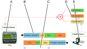
A | Fieldbus master (PLC) | B | Frame header |
C | User data to and from several virtual stations inside the Process Data Frame | D | Virtual station |
E | Controller vith multiple virtual stations |
A fieldbus master, normally a PLC, exchanges information with a number of remote nodes which are called fieldbus subordinates. The master communicates with one subordinate at a time. The master transmits a frame to the subordinate and receives another frame in response.
The PLC transmits data to a anybus module which then communicates to the controller that may contain identification data, task selection information and other signals.
A controller sends responses to the PLC through the anybus module that may contain event signals, status signals, tightening results and other signals.
The update frequencies of the process data may differ. The update frequency between the controller and the anybus module is around 100Hz and the update frequency between the anybus module and the PLC is around 500Hz.
The physical transmission link depends on the selected fieldbus type. A transmission consists of a Frame Header, containing address information, and a Process Data Frame, which contains all the data.
If the controller supports virtual stations, it is important to direct the correct information to each virtual station. The Process Data Frame may contain one or more Fieldbus maps, one for each virtual station.


