STT Tensioners
Tensioner
Product Information
General Information
Safety Signal Words
The safety signal words Danger, Warning, Caution, and Notice have the following meanings:
DANGER | DANGER indicates a hazardous situation which, if not avoided, will result in death or serious injury. |
WARNING | WARNING indicates a hazardous situation which, if not avoided, could result in death or serious injury. |
CAUTION | CAUTION, used with the safety alert symbol, indicates a hazardous situation which, if not avoided, could result in minor or moderate injury. |
NOTICE | NOTICE is used to address practices not related to personal injury. |
Warranty
Product warranty will expire 12+1 months after dispatch from Atlas Copco's Distribution Center.
Normal wear and tear on parts is not included within the warranty.
Normal wear and tear is that which requires a part change or other adjustment/overhaul during standard tools maintenance typical for that period (expressed in time, operation hours or otherwise).
Puller bars have its fatigue life and warrantied for 5000 cycles.
The product warranty relies on the correct use, maintenance, and repair of the tool and its component parts.
Damage to parts that occurs as a result of inadequate maintenance or performed by parties other than Atlas Copco or their Certified Service Partners during the warranty period is not covered by the warranty.
To avoid damage or destruction of tool parts, service the tool according to the recommended maintenance schedules and follow the correct instructions.
Warranty repairs are only performed in Atlas Copco workshops or by Certified Service Partners.
Atlas Copco offers extended warranty and state of the art preventive maintenance through its ToolCover contracts. For further information contact your local Service representative.
Website
Information concerning our Products, Accessories, Spare Parts and Published Matters can be found on the Atlas Copco website.
Please visit: www.atlascopco.com.
ServAid
ServAid is a portal that is continuously updated and contains Technical Information, such as:
Regulatory and Safety Information
Technical Data
Installation, Operation and Service Instructions
Spare Parts Lists
Accessories
Dimensional Drawings
Please visit: https://servaid.atlascopco.com.
For further Technical Information, please contact your local Atlas Copco representative.
Safety Data Sheets MSDS/SDS
The Safety Data Sheets describe the chemical products sold by Atlas Copco.
Please consult the Atlas Copco website for more information www.atlascopco.com/sds.
Country of Origin
For the Country of Origin, please refer to the information on the product label.
Dimensional Drawings
Dimensional Drawings can be found either in the Dimensional Drawings Archive, or on ServAid.
Please visit: http://webbox.atlascopco.com/webbox/dimdrw or https://servaid.atlascopco.com.
Overview
Unpacking and Storage
Open the package carefully to avoid damaging fixed accessories. Check the contents of the package for obvious damage upon receiving. Check the contents against the delivery note.
Storage for less than two months:
Preferably in its original packaging, protected from the elements.
Storage for longer than two months:
Preferably in its original packaging, protected from direct sunlight, placed vertically in a dry place.
A frame with a certified lifting point is not included in tensioners alone. It is included in tensioner kits. Tensioner kit also includes a case (box).
Technical Product Data
Technical Product Data can be found on either ServAid, or the Atlas Copco website.
Please visit: https://servaid.atlascopco.com or www.atlascopco.com.
Product Identification
Markings containing basic product related identification can be found on 2 places on the tensioner. One marking is on the back of the tensioner and one on the top of the endcap.
1 | Marking on the back of the tensioner Contains basic product related identification |
1 | Marking on the top of the endcap Contains basic product related identification |
These markings contain, for example:
Serial number
Model
Maximum pressure
Maximum load
Certification
Installation
Installation Instructions
Pre-Checks
Check the working load of the lifting equipment and weight of the tool.
Make sure that the lifting device is attached to the tensioner frame.
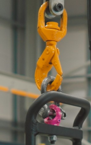
Make sure that all hydraulic and electric connections are connected properly.
Installing the STT Tensioner
Remove the tensioner from the pelicase.
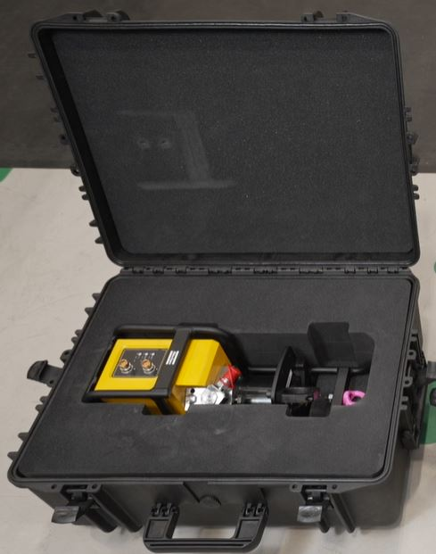
Insert the battery nutrunner (BCV) through the holder.
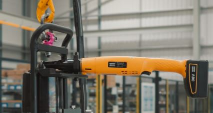
Align pin (ball) on the male square drive with female drive.
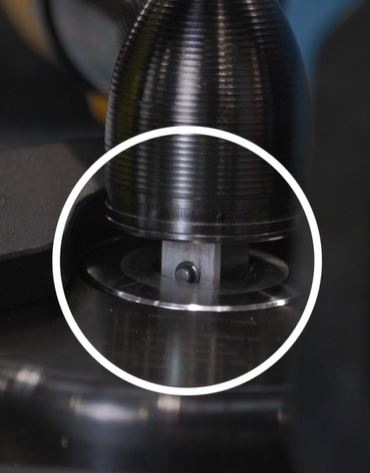
Push the pin (ball) by using the nutrunner disengagement key.
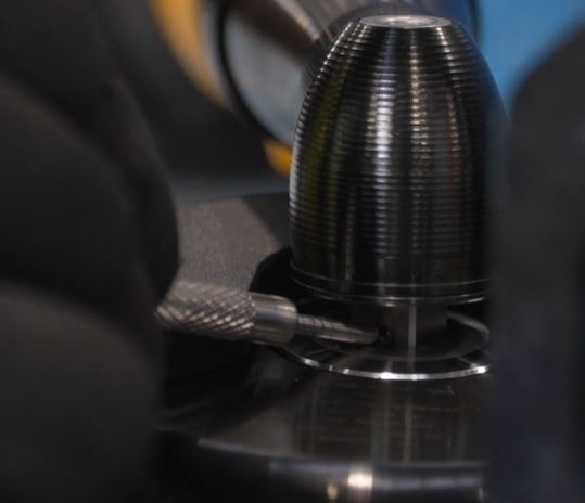
Tighten the nutrunner holder with rotating screw located below the frame.
Engage the click wrench to 3/8” square drive on the manifold.
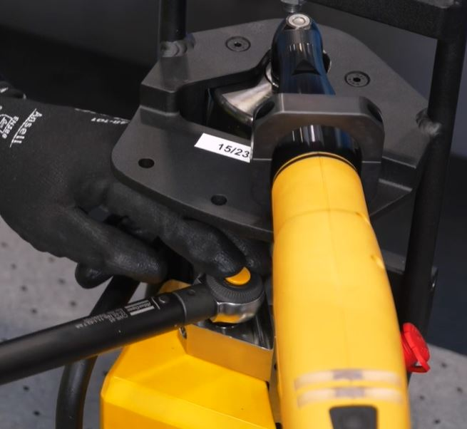
Battery Nutrunner and Wrench Disengagement
To disengage the click wrench, press the yellow push pin.
To disengage the nutrunner, push the puller bar to open the collar. Press the collar or the pin (ball) with the disengagement key.
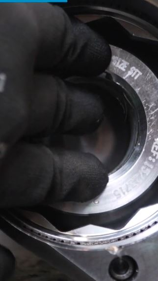
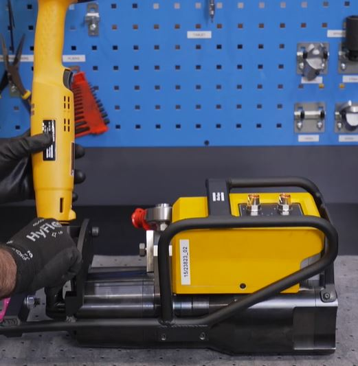
For more information about BCV, please visit https://servaid.atlascopco.com/AssertWeb/en-US/AtlasCopco/Catalogue/2247
Fore more information about CWR-85, please visit https://servaid.atlascopco.com/AssertWeb/en-US/AtlasCopco/Catalogue/8658
Operation
Ergonomic guidelines
Consider your workstation as you read through this list of general ergonomic guidelines and see if you can identify areas for improvement in posture, component placement, or work environment.
Take frequent breaks and change work positions frequently.
Adapt the workstation area to your needs and the work task.
Adjust for convenient reach range by determining where parts or tools should be located to avoid static load.
Use workstation equipment such as tables and chairs appropriate for the work task.
Avoid work positions above shoulder level or with static holding during assembly operations.
When working above shoulder level, reduce the load on the static muscles by reducing the weight of the tool, using for example torque arms, hose reels or weight balancers. You can also reduce the load on the static muscles by holding the tool close to the body.
Make sure to take frequent breaks.
Avoid extreme arm or wrist postures, particularly for operations requiring a degree of force.
Adjust for convenient field of vision by minimizing movement of the eyes and head during the work task.
Use the appropriate lighting for the work task.
Select the appropriate tool for the work task.
Use ear protection equipment in noisy environments.
Use high-quality inserted tools or consumables to minimize exposure to excessive levels of vibration.
Minimize exposure to reaction forces.
Operating Instructions
Preparation
Check that the bolt threads are not damaged.
Pre-tighten the nut to set the stud down.

The pre-tightening is very important as it will stop the bolt moving.
Wind the nut down to stop the stud rotation.
-
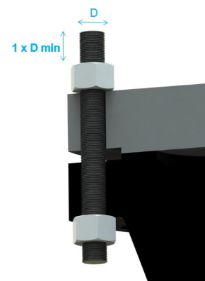
Measure the bolt protrusion before mounting the tensioner. Minimum bolt protrusion must be equal to the 1 x D of the bolt. If bolt protrusion is below the minimum, the tensioner can cause serious personal injury.
Mounting the Tensioner
Connect the balancer to the lifting eye bolt, see the picture.
Point and click on image to see more information:1
Lifting eye bolt

Do not lift the tensioner from any other point.
Move the tensioner above and in line with the bolt, close to the top mounting position.
Run down the tensioner on the top of the bolt keeping clear from the adjacent bolt/washer till it touches the flange face.

Hold or secure the tensioner with a lifting device.
Engage the manual click wrench to the 3/8” square drive on the top of the manifold.

The click wrench should not be set to more than 75 Nm as it can damage the IRTT inside the tensioner.
Turn the click wrench clockwise to engage the socket inside the tensioner.
Connecting the Tensioner
Connect the system cable to the tensioner and the pump. Any port on the pump can be used to connect the system cable, see the picture.
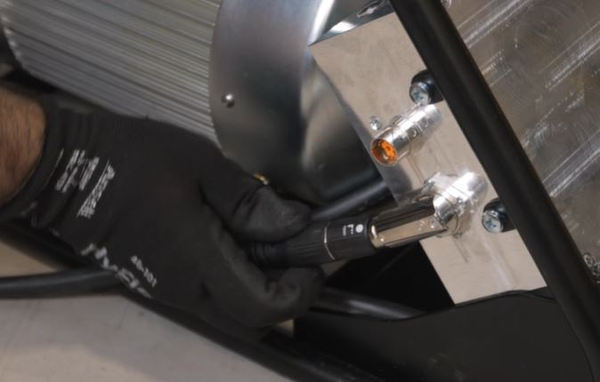
Any port on the tensioner can be used to connect with the pump, see the picture below.
Point and click on image to see more information:1
Status indicator with LEDs
Connect the hydraulic hose to the pump and the tensioner.
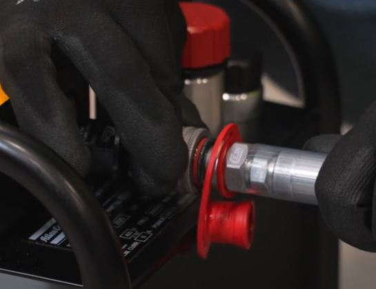
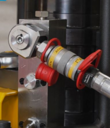
Connect the pump to the main power supply.

Keep the power button of the pump in the OFF position.
Connect the hand controller to the pump.

It is possible to connect the hand controller to the second port on the tensioner if needed.
Status Indicator - LED Lights
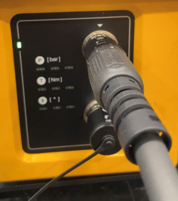
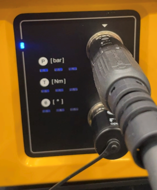
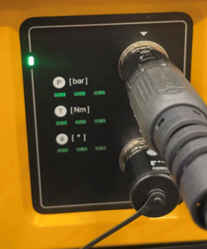
LED on the top left appears in different colors to show the status while the tool is connecting:
Lighter green light appears when the tool is trying to connect.
Blue light appears when the connection process is in progress.
Darker green light appears when the connection process is completed.
LEDs for pressure, torque and angle can appear in sequences shifting from left to right, or from right to left:
When LED lights illuminate in sequence from left to right, start increasing the pressure, torque, or angle, depending on which row is illuminated.
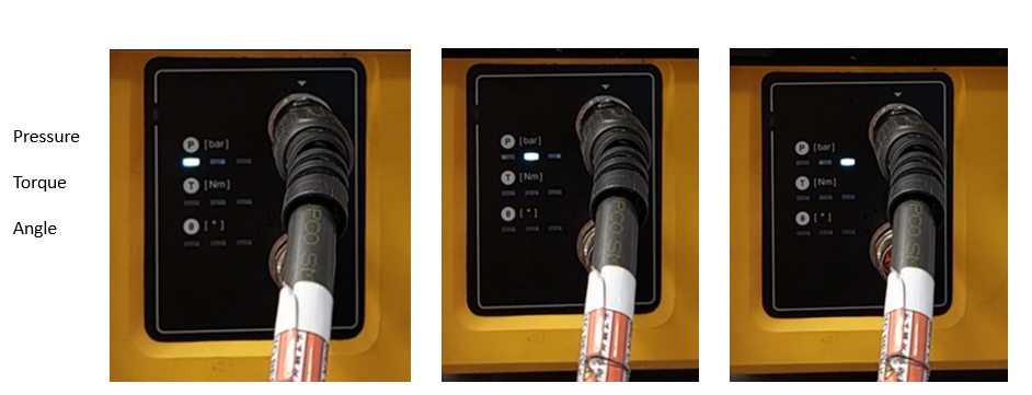
When LED lights illuminate in sequence from right to left, start decreasing the pressure, torque, or angle, depending on which row is illuminated.
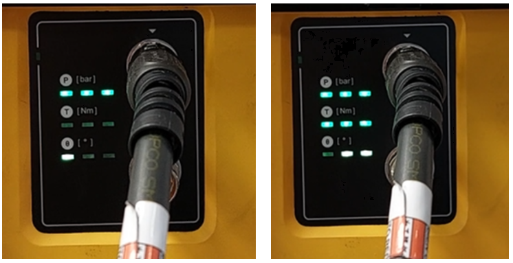
When the pressure reaches the target pressure, all 3 LEDs in the first row (pressure) will turn green which means that the pressure is OK. The same is valid for torque and angle.
Generally, LEDs indicate the following:
Red light means error.
White light - check the instruction on the hand controller.
Green light means OK.
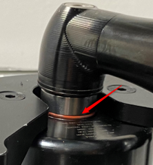
The max stroke indicator on the puller bar should not be visible while pressuring the tensioner. If visible, stop and adjust the position of the puller bar on bolt so that the max position is not reached until the required pressure is achieved. Otherwise, if done repeatedly, it can physically damage the internal components of the tensioner.
Service
Preventing ESD Problems
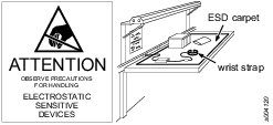
The components inside the product and controller are sensitive to electrostatic discharge. To avoid future malfunction, make sure that service and maintenance is carried out in an ESD approved work environment. The figure below shows an example of an appropriate service work station.
Maintenance Instructions
Service Recommendations
Preventive maintenance is recommended at regular intervals. See the detailed information on preventive maintenance. If the product is not working properly, take it out of service and inspect it.
If no detailed information about preventive maintenance is included, follow these general guidelines:
Clean appropriate parts accurately
Replace any defective or worn parts
Overhaul
It is important to plan the maintenance of the tool on time, because the tool will stop working after 5000 cycles. The hand controller prevents the tool exceeding 5000 cycles.
The warning will be displayed several times:
When 250 cycles are left.
When100 cycles are left.
When 50 cycles are left.
The last 10 times the warning will be displayed each time. After that, the system will stop the tensioning work.
General Service and Maintenance Safety
Always wear impact-resistant eye and face protection when involved with or near the operation, repair or maintenance of the tool or changing accessories on the tool.
Disconnect the power supply and depressurize the hydraulic system before disconnecting or connecting hoses, fittings, or accessories or adjusting or dismantling the tool.
All investigation, maintenance or repair work should only be carried out when the tensioner is at zero pressure.
Always examine the condition of the elements that assemble the hydraulic circuit. If there are any faulty elements, contact the customer center to replace it with another element with the same characteristics in proper condition. Only qualified and trained personnel can do maintenance and improvement services on this device.
Cleaning Instruction
Equipment should be wiped off with a damp/wetted cloth.
Contact your Atlas Copco service technician for cleaning advice as per current recommendations and for your particular tool.
Regular Cable Inspections
Regularly inspect the power cable and the tool cable. If the cables show any sign of damage, replace them.
Recycling
Environmental Regulations
When a product has served its purpose it has to be recycled properly. Dismantle the product and recycle the components in accordance with local legislation.
Batteries shall be taken care of by your national battery recovery organization.