Tightening Steps
This section lists the tightening steps that are valid for the Power Focus XCPower Focus XC Controller.
General Parameters
Name
It is possible to rename each step, if needed.
Rotational direction
Each of the tightening steps can run either forward, that is to make a tightening, or reverse, to loosen the screw slightly. The arrows indicate this direction. Many of the tightening steps have a direction hard-coded to forward, for example Tighten to Angle, or Tighten to Torque. Steps such as Loosen to Angle or Loosen to Torque have their direction automatically set to reverse.
The reverse setting is not allowed for tools configured with Gear Front Attachment (GFA) of type open end. The tightening direction of the tightening program must be the same as the tightening direction of the open end tool for a tightening to be allowed to be run. It is possible to assign a loosening program to a tightening program for an open end tool, but if the direction switch is set to run the loosening program, the tool will be locked.
Step category
For each step, there is an option to choose a step category. By selecting step category, the NOK tightenings will be listed in the event result view with related detailed status together with the corresponding multistep error information. If no selection is made, the detailed status will be set to "uncategorized multistep error". The related detailed status can be customized.
Angle window
A joint is considered Hard if the screw is tightened to its full torque and it rotates 30 degrees (or less) after it has been tightened to its snug point. A Soft joint rotates 720 degrees or more after it has been tightened to its snug point. The hardness parameter defines the Angle Window for the gradient calculation. The harder the joint - the smaller the angle window.
Speed Ramp / Acceleration (only available in ToolsTalk 2)
For most of the steps it is possible to specify how the acceleration to the target speed should be achieved. Three different settings are possible; Hard, Soft and Manual. The acceleration defined will be used whenever a step is started. Regardless whether the tool is already running with speed at the beginning of the step, the ramp will be used to accelerate to the target speed of the step. This will be the case even if the speed at the start of the step is higher, or lower than the target speed.
Speed ramp - Hard and Soft mode:
Acceleration | Speed ramp used |
|---|---|
Hard | 2000 rpm/s (Speed Ramp between 1000 and 10000 rpm/s is a Hard acceleration.) |
Soft | 500 rpm/s (Speed Ramp between 200 and 1000 rpm/s is a Soft acceleration.) |
Speed ramp - Manual mode:
Parameter | Default value | Minimum limit | Maximum limit |
|---|---|---|---|
Speed | 60 rpm | Must be > 0 | Must be <= Tool Max Speed |
Acceleration | 500 rpm/s | Must be > 0 | Must be <= Tool Max Acceleration |
Using speed shifts
You can define 1-5 angle triggers or torque triggers during a step, where the speed will shift.
The speed shifts can be added in the Configuration field.
Within one step, all the speed shift triggers are based on the same property (either torque or angle). They cannot be mixed within one step.
To add a speed shift:
In the dialog box of a step that can have speed shifts, select Add speed shift. Then, select an angle range or a torque range.
The Speed Shift Angle/Torque fields open.Add values according to the table below:
Parameter
Description
Angle/Torque trigger
Must be > 0
Speed
Must be >0
Speed ramp type
Hard or soft
The Torque triggers and Angle triggers must be less than the step target, depending on the type of the step and the trigger type.
The Torque trigger and Torque speed also validate against the Max torque and Max speed of the tool.
A warning or error indicator occurs whenever the Speed Shift settings exceed either the tool max values or step max values.
Controlling braking behavior (Ergo stop/Inertia)
The braking behavior of a Multistep tightening program can be controlled at two possible locations in the program: in a step preceding a reversal of direction of the tightening, and/or at the final step of the tightening program. At other locations in the Multistep program, the braking parameters will not be available in the step's general settings. Braking can be set to either Ergo stop or Inertia. Inertia will brake the tool completely, while Ergo stop will allow for a more ergonomic slowing down of the tightening.
To set the type of braking, go into the settings for the step, and set the Brake configuration dropdown to Ergo stop or Inertia. Inertia has no additional parameters.
Ergo stop parameters
Parameter | Description |
|---|---|
Adaptive brake | Set the Adaptive Brake to On or Off |
Ramp time | Only available when Adaptive Brake is set to Off. Insert time in ms. |
List of individual steps
The following tightening steps are not supported for tools configured with Gear Front Attachment (GFA) of type open end:
A - Loosen to Angle
TrR - Loosen to Trigger Release
T - Loosen to Torque
E - Engage
SR - Socket Release
DT - Tighten to DynaTork
TP - TensorPulse
C - Clutch
This step will run the tool with the programmed Speed in forward direction until the Clutch has been released. When the tool has reported the release of the Clutch the step will finish with OK status.
A tightening program using the Clutch step cannot have any other step assigned.
This step is only valid for the Clutch tools BCV-RE and BCP-RE.
Parameter | Description |
|---|---|
Speed Control | One Speed or Two Speed |
Final Speed | Sets the final speed of the program [rpm] |
Speed Ramp | Switch where speed ramp can be chosen [Hard, Soft] |
Rehit | Rehit detection set to On or Off |
Rehit angle | Sets the rehit angle [°] |
CL - Clutch Loosening
This step will run the tool with the programmed speed in reverse direction until the tool trigger is released.
A loosening program using the Clutch step can't have any other step assigned.
This step is only valid for the Clutch tools BCV-RE and BCP-RE.
Parameter | Description |
|---|---|
Final | Sets the speed of the program [rpm] |
W – Wait
In this step the tool waits the specified amount of time. The tool does not rotate while waiting.
The tool waits the specified time. If the hold position is set to On the tool holds the position during the Wait time.
SR - Socket Release
This step runs the tool with speed n in the backward direction until the target angle is reached. The target angle is measured from the start of the step.
This step is only allowed to use as the last step in the tightening path of a multistep tightening program. However, it is possible to add a sync point after this step.
Parameter | Description |
|---|---|
Target angle | The angle target. Default: 3º , must be > 0 |
Speed ramp type | Hard, soft, or manual. Default: Hard. If you select Manual, the Speed ramp field opens. |
Speed ramp | If Speed ramp type is Manual, this field opens. Default: 500 rpm/s. |
Speed | Default: 60 rpm. |
DI – Run Until Digital Input
This steps runs the tool, in the direction defined by parameter Direction, until the input specified by Digital Input goes high or low depending on the value of Stop Condition.
This step is not available for STB tools.
Parameter | Description |
|---|---|
Direction | Forward, or Backward |
Digital Input | One of the following local digital inputs on the controller can be selected:
|
Stop Condition |
|
Speed (rpm) | Default: 60 rpm. |
Speed ramp type | Hard, soft, or manual. Default: Hard. If you select Manual, the Speed ramp field opens. |
Speed ramp | Available if Speed ramp type is Manual. Default: 500 rpm/s. |
A – Tighten to Angle
This step runs the tool until the target angle is reached. The target angle is measured from the start of the step.
Parameters
Parameter | Description |
|---|---|
Target angle | The angle target. Must be > 0. |
Speed | Default: 60 rpm. |
Speed ramp type | Hard, soft, or manual. Default: Hard. If you select Manual, the Speed ramp field opens. |
Speed ramp | If Speed ramp type is Manual, this field opens. Default: 500 rpm/s. |
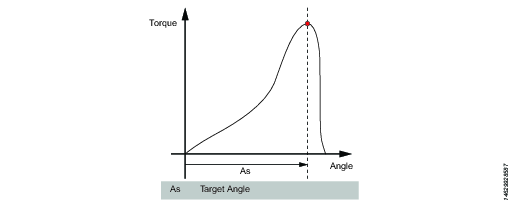
A – Loosen to Angle
This step runs the tool with the speed n in the backward direction until the angle target is reached. The target angle is measured from the start of the step.
Parameters
Parameter | Description |
|---|---|
Target angle | The angle target. Must be > 0. |
Speed | Default: 60 rpm. |
Speed ramp type | Hard, soft, or manual. Default: Hard. If you select Manual, the Speed ramp field opens. |
Speed ramp | If Speed ramp type is Manual, this field opens. Default: 500 rpm/s. |
TrR – Loosen to Trigger Release
This step runs in the backward direction until the tool trigger is released (loosen). It can only be used as a last step in a program.
For STB tools, this step is only applicable for loosening programs.
Parameter | Description |
|---|---|
Speed | Numerical value for rotation speed; in rpm. |
Speed Ramp Type | List of options where speed ramp can be chosen [Hard, Soft, Manual] |
TTTR – Tighten to Trigger Release
This step runs until the tool trigger is released (tighten). It can only be used as a last step in a tightening program.
Parameter | Description |
|---|---|
Speed | Numerical value for rotation speed; in rpm. |
Speed Ramp Type | List of options where speed ramp can be chosen [Hard, Soft, Manual] |
Tighten to yield, method 2 (YM2)
This step runs the tool with the specified speed in the forward direction until the yield point is detected.
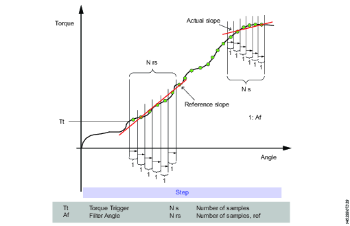
Search for the yield point starts when the torque has reached Tt. The average of the torque over Af degrees is calculated. This procedure is repeated N rs times.
A reference slope is calculated with linear regression over the N rs points. After that, new average values are continuously calculated over A f degrees.
The actual slope is calculated with linear regression over the last N s average points. The yield point is reached when the slope is less than Py % of the reference slope.
Parameter | Description |
|---|---|
Target torque | Must be > 0. |
Filter angle | Default: 1. Must be > 0. |
Number of samples | Default: 6. Must be >=4. |
Number pf samples, reference | Default: 6. Must be >=4. |
Yield point percentage | Default: 90%. Must be >20%. |
Speed | Default: 60 rpm. Must be > 0. |
Speed ramp type | Hard, soft, or manual. Default: Hard. If you select Manual, the Speed ramp field opens. |
Speed ramp | If Speed ramp type is Manual, this field opens. Default: 500 rpm/s. |
T - Tighten to Torque
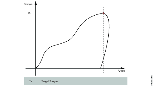
This step runs the tool with the programmed speed in forward direction until the target torque is reached.
Parameter | Description |
|---|---|
Target torque | The torque target. Must be > 0. |
Speed ramp type | Hard, soft, or manual. Default: Hard. If you select Manual, the Speed ramp field opens. |
Speed | Default: 60 rpm. Must be > 0. |
Speed ramp | If Speed ramp type is Manual, this field opens. Default: 500 rpm/s. |
T – Loosen to Torque
This step runs the tool with the speed in the backward direction. For the step to be active, the torque must first exceed 110 % of the Target torque. The Target torque should be set to a positive value. After reaching the target torque, the step runs until the torque drops below the target torque.
Parameter | Description |
|---|---|
Target torque | The torque target. Must be > 0. |
Speed ramp type | Hard, soft, or manual. Default: Hard. If you select Manual, the Speed ramp field opens. |
Speed | Default: 60 rpm. Must be > 0. |
Speed ramp | If Speed ramp type is Manual, this field opens. Default: 500 rpm/s. |
T+A – Tighten to Torque Plus Angle
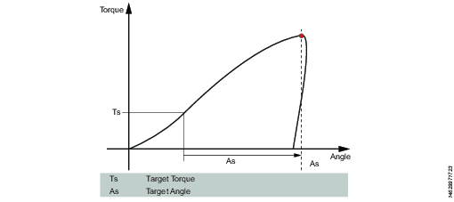
This step runs the tool until the target torque is reached. From this point it continues to run an additional target angle.
Parameter | Description |
|---|---|
Target torque | The torque target. Must be > 0. |
Target angle | The angle target. Must be > 0. |
Speed ramp type | Hard, soft, or manual. Default: Hard. If you select Manual, the Speed ramp field opens. |
Speed ramp | If Speed ramp type is Manual, this field opens. Default: 500 rpm/s. |
Speed | Default: 60 rpm. |
T|A – Tighten to Torque or Angle
This step runs the tool with the speed n in the forward direction until the first of either torque target or angle target is reached. The torque and angle measurements start at the beginning of the step.
Parameter | Description |
|---|---|
Target torque | Must be > 0. |
Target angle | Must be > 0. |
Speed | Default: 60 rpm. Must be > 0. |
Speed ramp type | Hard, soft, or manual. Default: Hard. If you select Manual, the Speed ramp field opens. |
Speed ramp | If Speed ramp type is Manual, this field opens. Default: 500 rpm/s. |
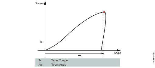
T&A – Tighten to Torque and Angle
The tool runs until with the specified speed in the forward direction until both target torque and target angle are reached. The target torque and the target angle must be set to > 0.
Parameter | Description |
|---|---|
Target torque | Must be > 0. |
Target angle | Default: 0. Must be > 0. |
Speed | Default: 60 rpm. Must be > 0. |
Speed ramp type | Hard, soft, or manual. Default: Hard. If you select Manual, the Speed ramp field opens. |

DT – Tighten to DynaTork
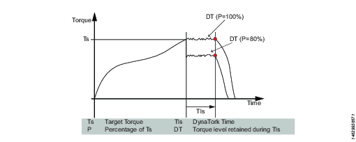
This step runs the tool with speed n in the forward direction until the Target torque is reached. The tool will then hold the current constant at the DynaTork Percentage of Target torque during the DynaTork time.
To avoid overheating of the tool, it is strongly recommended to never run DynaTork to more than 40% of the maximum torque of the tool.
Parameter | Description |
|---|---|
Target torque | The torque target. Must be > 0. |
DynaTork Time | The time DynaTork will be active. |
DynaTork Percentage | The percentage of Torque target. |
Speed ramp type | Hard, soft, or manual. Default: Hard. If you select Manual, the Speed ramp field opens. |
Speed ramp | If Speed ramp type is Manual, this field opens. Default: 500 rpm/s. |
Speed (rpm) | Default: 60 rpm. |
Y – Tighten to Yield
This step is not available for STB tools.
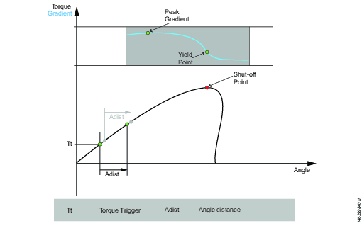
This strategy runs the tool with the speed in the forward direction until the yield point is detected. The yield point is found by monitoring the torque gradient from the point where the torque goes above the Trigger Torque level, calculated based on Torque and Angle distance measurements. The Angle distance parameter is set according to the specified hardness of the joint.
Set the Gradient angle window (for hard joint, for soft joint or for manually setting of the Angle window). If Manual is selected, the Angle Window must be set. A joint is considered Hard if the screw is tightened to its full torque and it rotates 30 degrees or less after it has been tightened to its snug point. A Soft joint rotates 720 degrees or more after it has been tightened to its snug point. The hardness parameter defines the Angle Window for the gradient calculation. The harder the joint - the smaller the angle window.
Parameter | Description |
|---|---|
Gradient Angle Window | Specifies Angle Window:
|
Angle Window | Available when Gradient Angle Window is set to Manual. Must be > 0 and <= 100. |
Trigger Torque | The angle measurement starts at this trigger. Must be >= 0 and < Tool MaxTorque. |
Damping | Frequency in which the gradient is being calculated. Must be > 0 and < 100 and < Angle window. |
Yield Point Percentage | Must be >= 20 % |
Speed | Default: 60 rpm. Must be > 0. |
Speed ramp type | Hard, soft, or manual. Default: Hard. If you select Manual, the Speed ramp field opens. |
Torque Filter Type | The type of the filter:
|
Cut-off Frequency | Needs to be specified when Torque Filter Type is set to Low pass:
|
Number of Samples | Needs to be specified when Torque Filter Type is set to Sliding Average:
|
ThCT – Thread Cutting to Torque
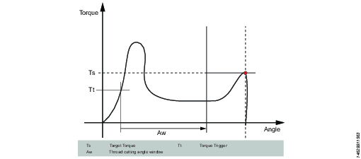
The Thread Cutting to Torque function enables tightening where the Rundown torque required is greater than the Rundown complete torque, for example when tightening thin layers of metal using self-threading (or selftapping) screws. The tool runs in forward direction until the Thread Cutting Angle (Aw) is reached. The thread cutting angle window is measured from when the torque passes Thread Cut Trigger Torque (Ttc) for the first time. From the point where Thread cutting angle is reached, the step continues to run until the Target Torque (Tt) is reached.
Parameter | Description |
|---|---|
Target torque | Must be > 0. |
Thread Cutting Angle Window | Default: 0. Must be > 0. |
Trigger Torque | The angle measurement starts at this trigger. |
Speed | Default: 60 rpm. Must be > 0. |
Speed ramp type | Hard, soft, or manual. Default: Hard. If you select Manual, the Speed ramp field opens. |
RD – Rundown
This step is not available for STB tools.
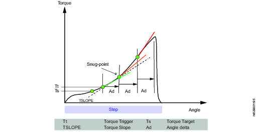
Rundown step is the part of the tightening from when the screw enters the thread until just before the screw head touches the underlying surface and snug point is reached. The torque required during rundown does not contribute to any clamping force.
This step runs the tool with the speed in the forward direction, and depending on the Rundown Type, Torque or Snug the step behavior is as follows:
Rundown Type: To Torque: The step stops when the specified target torque is found.
Rundown Type: To Snug: The snug gradient calculation starts at the specified torque trigger level Tt. If no torque trigger is set the gradient calculation is started at the start of the step.
The slope calculation is made between two angle points Ad degrees apart and is calculated as: (Tn – Tn-1) / (An – An-1) and as soon as two slopes after each other are larger than TSLOPE the snug point is found.
Parameter | Description |
|---|---|
Rundown type | To Torque or To Snug. |
Target torque | Default: "not set". Must be > 0. |
Speed | Default: 60 rpm. Must be > 0. |
Speed ramp type | Hard, soft, or manual. Default: Hard. If you select Manual, the Speed ramp field opens. |
Speed ramp | If Speed ramp type is Manual, this field opens. Default: 500 rpm/s. |
Trigger Torque | If Rundown type is To Snug, the Trigger torque field is displayed. Default: "not set". Must be > 0. |
Delta Angle | If Rundown type is To Snug, the Delta angle field is displayed. Default: "0". Must be > 0. |
Torque Rate | If Rundown type is To Snug, the Torque rate field is displayed. Default: "0". Must be > 0. |
E - Engage
This step is not available for STB tools.
This step runs the tool in both directions until the socket engages the screw. The step continues until Target torque or Target angle is reached, provided that Continue if not Engaged is set to Yes. If Target Angle is reached in any direction, the direction is reversed. Limit the search iterations by entering Max Engage Attempts. If Target Torque is reached in any direction the step will finish with OK status.
Ext - External Result
External result is a strategy used when an OK tightening is indicated by an external digital signal (and not by torque or angle values measured during tightening). This external signal can be provided through any means that can provide a digital signal into the Power Focus XC.
When the signal is sent, the result view (logged data) will show the value of the Target parameter provided in the tightening program (specified torque value, angle value, or text string). These (torque and angle) values do not represent actual measured values, but only inserted text.
Parameter | Description |
|---|---|
Torque <Target torque> | Numerical value for desired displayed target torque value. A signal could for example come from a Click Wrench and display <Target torque>. |
Angle <Target angle> | Numerical value for desired displayed target angle value. A signal could for example come from a Click Wrench and display <Target angle>. |
Text | Alphanumerical string for desired displayed text. For example: "Oil has been changed". |
MWR - Mechatronic Wrench
Mechatronic Wrench is a specialized step that can be used only in conjunction with the Mechatronic Wrench (MWR).
This step cannot be used in combination with other steps. No restrictions can be used with this step. By default, the step has three monitors: Peak Torque, Angle, and Click.
Parameter | Description |
|---|---|
Loosening limit | Numerical value for negative torque (i.e. torque in the loosening direction) at which point the tightening result is marked as NOK (False direction of tightening (loosen)); in Nm. |
Tool Size | Numerical value for the specific length of the end fitting tool installed on the MWR-TA; in mm. |
Tool Bend | Numerical value for the end fitting tool installed on the MWR-TA; in °/Nm. |
Rehit Angle Window | Numerical value for the angle for determining if the screw was already tightened if the torque is reached; in °. |
Max Angular Rate | Numerical value for the max rate at which the screw can be tightened; in °/s. |
WP - Wrench Production
Strategy used for the quality test of the tightening performed with the STwrench.
Parameter | Description |
|---|---|
Control Strategy | The Wrench Production step type can be configured with the following control strategies.
|
Based on the control strategy selected, a combination of some of the parameters listed below will be displayed.
Parameters | Description |
|---|---|
Target Torque | Defines the target torque for tightening step. |
Measure torque at | Specifies where the torque will be measured. Choose between Peak torque or Peak angle.
|
Angle search limit | This is an offset that is used to the set the torque result value for a tightening. Measure torque at must be set to Peak Angle for this parameter to be available. |
Ratchet time | Numerical value for ratchet time which is by default 5000 ms. This allows the operator to release the torque for a while and recharge during the tightening operation. If the Ratchet time is exceeded the result of the tightening is marked as NOK with the reason "Tightening timeout". |
End cycle time | Numerical value in ms to indicate the end cycle time. Applied when torque goes below the rundown complete |
Torque correction coefficient | The parameter is used to correct the torque reading when using an extension or torque multiplier on the wrench. Default value is 1. |
Angle correction | The parameter is used to correct the angle reading when using an extension or torque multiplier on the wrench. Default value is 0. |
Target Angle | Defines the target angle for tightening step. |
Rehit detection | On or Off. Rehit detection can be used to determine when a tightening is a rehit based on the angle limit setting. Angle limit for rehit is enabled if Rehit direction is set to On. |
Linear slope coefficient | Linear slope coefficient characterizes the joint stiffness in the linear part of the curve, as torque/angle slope in the Nm/Deg measurement unit. |
Compensate value | Choose between Average torque and Peak torque. The Compensate value specifies how the PVT will be calculated. Average torque - The PVT will be based on an average calculated using the following:
Peak torque - The PVT will be based on the peak value measured before snug was detected. |
Delay monitoring | PVT calculation will not start before this window has been passed, starts at tightening start. |
PVT interval | Sets how many degrees the PVT window shall be calculated for, start from the PVT distance point. |
PVT distance | Sets how many degrees prior to snug the system shall start the PVT window. |
Prevailing torque min | Prevailing torque minimum limit. |
Prevailing torque max | Prevailing torque maximum limit |
WQ - Wrench Quality
Strategy used for quality test of tightenings with the STwrench.
Parameter | Description |
|---|---|
Control Strategy | The Wrench Quality strategy can be configured with the following control strategies.
|
Based on the control strategy selected, a combination of some of the parameters listed below will be displayed.
Parameters | Description |
|---|---|
Ratchet time | Numerical value for ratchet time which is by default 5000 ms. This allows the operator to release the torque for a while and recharge during the tightening operation. If the Ratchet time is exceeded the result of the tightening is marked as NOK with the reason "Tightening timeout". |
Torque correction coefficient | The parameter is used to correct the torque reading when using an extension or torque multiplier on the wrench. Default value is 1. |
Angle correction | The parameter is used to correct the angle reading when using an extension or torque multiplier on the wrench. Default value is 0. |
Target Angle | Defines the target angle for tightening step. |
Rehit detection | On or Off. Rehit detection can be used to determine when a tightening is a rehit based on the angle limit setting. Angle limit for rehit is enabled if Rehit direction is set to On. |
Linear slope coefficient | Linear slope coefficient characterizes the joint stiffness in the linear part of the curve, as torque/angle slope in the Nm/Deg measurement unit. |
TP - TensorPulse
Before using TensorPulse tightening step, it is mandatory that the following license type is installed on the controller:
Low Reaction Strategies
TensorPulse is valid only for the following tools: ETV-STR61-100-13, ETV-STR61-70-13, ETV-STR61-50-10.
This step generates tightening pulses in the forward direction, until the torque target is reached.
If running TensorPulse tightening step, use the necessary PulseDrive socket/adapter.
If TensorPulse tightening step runs without the PulseDrive socket/adapter, all the tightenings are NOK. The step error “PulseDrive socket/adapter not detected” shows for no PulseDrive socket/adapter.
Parameter | Description |
|---|---|
Torque Target - Ts | Torque Target must range from 0 through the maximum torque of the tool. |
Pulse Energy - Pe | Pulse Energy is used to control the amount of energy/current in each pulse. Pulse Energy must range from 10% through 100 %. |
Reaction Force Tuning Factor | Retention Force Tuning Factor is used to tune the reaction force when running TensorPulse step. It is the power that moves the tool in the opposite direction after each pulse. Retention Force Tuning Factor must range from 0 through 100 %. |
In the trace, the angle reversal means that the tool rotates backward to enable pulsing, but the bolt head does not necessarily rotate backward because of the PulseDrive socket/adapter.


