Torque (Control) / Prevailing Torque (Monitor)
This strategy guides the operator in tightening joints with prevailing torque to the torque target value. It is particularly useful when the joint's prevailing torque value is higher than the final torque target.
The strategy calculates the prevailing torque value in a defined angle Window Length in order to subtract the prevailing torque value from the tightening's absolute peak torque value and confirm whether the desired torque target value is actually reached or not.
Parameter | Description |
|---|---|
Required tag number | A specific number must be written in the TAG of the end fitting tool. |
Name | Name of the tightening program. |
Program start | Torque value from which the tightening operation starts. |
Torque min | Lower torque limit. |
Torque max | Higher torque limit. |
Maximum torque limit | If the torque applied reaches this limit, the message Change screw is shown on the wrench display. |
Target torque | Torque target value. |
Trigger torque | Torque value from which the angle measurement starts (usually set to 50% of the Target torque). |
Delay monitoring | Angle value after which the angle reading must start. |
Start Angle Distance | Angle value that, spanning in reverse direction from the snug point, defines where the angle Window Lenght starts. |
Window Length | Angle interval during which the compensate value is calculated. |
Compensation | Method to define the tightening result:
|
High Limit | Upper torque limit value to get an OK result. High Limit must be > 0 |
Low Limit | Lower torque limit value to get an OK result. Low Limit must be ≥ 0 |
Use value | Method to define how to calculate the prevailing torque value in the angle Window Length interval:
|
Torque units | This parameter is not editable. |
Torque correction coefficient | When extensions are used, the wrench measurement might be compensated to show a more accurate torque value. To calculate the correction coefficient, please refer to How to calculate the Torque Correction Coefficient. When extensions are not used, Torque correction coefficient = 1. |
Angle correction | When extensions cause additional wrench bending, the wrench angle measurement can be compensated to show a more accurate angle value. When extensions are not used, Angle correction = 0. |
Batch size | Number of tightenings the batch will perform. |
Max consecutive NOK | Number of accepted consecutive NOK to have an OK result. |
End cycle time | Starts when the torque goes below the Program start after reaching the 3rd percentage. |
Ratchet time | Starts when the torque goes below the Program start without reaching the 3rd percentage value. This allows the operator to release the torque for a while and recharge during the tightening operation. |
The angle Window Length, in which the prevailing torque value is calculated, starts at the angle degrees set in Start Angle Distance measured in reverse direction from the snug point, which is automatically calculated by the system in real time. The angle window then spans in opposite direction for the angle degrees set in Window Length. The calculated prevailing torque value can be either the mean or the peak torque value measured during the Window Length according to the Use value set for the tightening operation.
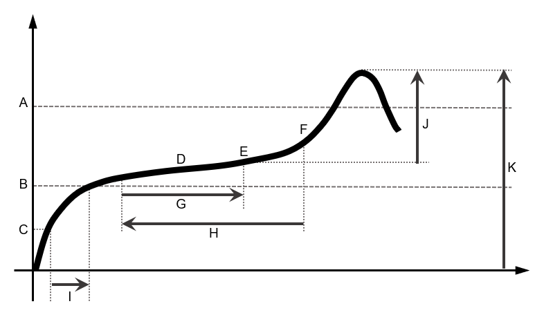
A | High limit | G | Window Length |
B | Low limit | H | Start Angle Distance |
C | Trigger torque | I | Delay monitoring |
D | Mean torque during angle Window Length | J | Peak torque value compensated with the subtraction of he prevailing torque. |
E | Peak torque during angle Window Length | K | Peak torque value without compensation. |
F | Snug point |
Torque results:
If Compensation is set to On, the calculated prevailing torque value is subtracted from the absolute peak torque value, and the torque final result value is the difference between the torque peak value and the prevailing torque value.
If Compensation is set to Off, the calculated prevailing torque value is not subtracted from the absolute peak torque value, and the torque final result value is the tightening's peak value.
During the tightening operation, LEDs, buzzer and vibration are activated as follows:
LEDs:
White LED: activated when the torque value goes over the smartHEAD's Min load value.
First, second and third radial gradient LEDs turn green in sequence when the three thresholds defined for the tool in use are reached.
For further information, refer to Tool LEDs.All three radial gradient LEDs green: torque between Low limit and High limit.
All three radial gradient LEDs red: torque over High limit.
Buzzer:
Starts when the torque goes over the Program start value; the signal increases when the 1st percentage, the 2nd percentage, the 3rd percentage.
Vibration:
Starts together with the third radial gradient LEDs.
At the end of the tightening operation, LEDs, buzzer and vibration are activated as follows:
LEDs behave according to the configuration of Result Indicator and Duration defined for the tool in use.
For further information, refer to Tool LEDs.Buzzer
Two beeps indicate the end of the operation; if the final result is in the red area, the signal in continuous.
To stop the buzzer, start a new tightening operation or press a button on the tool controller.
Vibration:
Stays active until the torque applied is released.


