Smart Tensioning System Working Guide
Instruction Supplement
Overview
System Overview
1 | Smart Tentec Tensioner (STT) |
2 | Power Focus Hand Controller (PFHC) |
3 | SP2000 pump - Hydraulic power pack |
4 | Hydraulic hose |
5 | System cables (2 pieces) |
6 | Battery nutrunner BCV BL-30-10 (clutch type) |
7 | Reversible torque wrench CWR-85 |
System Components
1 | Power focus hand controller (PFHC) |
2 | STS system cable, 6 meters - 2 pieces |
3 | BCV BL-30-10 - Click type battery nutrunner |
4 | BCV Battery 36V |
5 | Battery charger |
6 | CWR-85 Click wrench |
7 | 3/8" reversible head |
8 | Place for BCV disengage key |
Always place the articles back in the box to avoid loss. Check that the batteries are fully charged before taking in field.
STT - Smart Tentec Tensioner
1 | Lifting point |
2 | Engagement for the battery nutruner |
3 | Engagement point for the click wrench |
4 | Hydraulic connection |
5 | Pressure sensor Torque transducer Angle sensor |
6 | Status indicators |
Important:
The eye bolt on the frame is a secure lifting point.
Overshooting the click wrench can damage sensors.
Avoid pressurised hose movements.
Before transportation, remove the nutrunner and the click wrench.
Stop the operation immediately in the event of oil leakage.
Do not use any other tools as a replacement for nutrunner and click wrench.
SP2000 Hydraulic Power Pack
1 | Hydraulic coupling |
2 | Oil filing neck (red cap) |
3 | Certified lifting point |
1 | Phase rotation slot |
Important:
Check the oil level since it can drop at first start which will cause the system to stop if it is too low. Top up with the same grade of oil.
Use the correct cap, black or red accordingly. The black cap for transportation, the red cap when the pump is in use.
Power supply is 400V, 50/60 HZ, 3 phase. If no pressure builds up the first time, change phase by rotating the pins inside the socket.
Make sure to lock the coupler after engagement.
The system cables can be connected from any of two ends. To lock the system cable to the connector, push until it clicks. To remove the cable, twist and pull.
PFHC - Power Focus Hand Controller
1 | Display |
2 | USB hatch |
3 | Display keypad |
1 | Barcode scanner |
2 | Magnets |
3 | De-pressurize button |
4 | Pressurize button |
Important:
The PFHC can be connected with a cable to the hydraulic pump or to the tensioner.
The magnets on the hand protection make it possible to stick the controller on the tower body.
The screen of the hand controller is not a touch screen for safety reasons.
BCV - Clutch Type Battery Nutrunner
The clutch type battery nutrunner, model BCV BL-30-10 has range 10-30 Nm.
1 | Bright LED Illuminates the application in the dark |
2 | LEDs For visual feedback |
3 | Buzzer For additional feedback |
4 | Trigger |
5 | Battery The position is flexible, it can be reversed |
6 | Ergonomic handgrip Reduces user's fatigue |
7 | Direction switch Single press |
Important:
Check battery status by removing the battery and pressing the button inside.
To change direction, press the direction switch button shortly and release, do not hold it for long. Holding the direction switch button for longer than 3 seconds can change its function.
To remove the nutrunner from the tensioner, use the disengage key.
For more information about BCV, please visit https://servaid.atlascopco.com/AssertWeb/en-US/AtlasCopco/Catalogue/2247
CWR - Torque Wrench
Torque wrench model CWR-85 has range 15-85 Nm.
1 | Disengagement pin Press and lift |
2 | Direction switch Turn to change the direction of rotation |
3 | 3/8" reversible head |
4 | Lever arm Do not grip for tightening |
5 | Tactile and audible "click" feedback |
Important:
Do not overshoot the click.
Do not push hard to achieve torque. It can break the internal sensors of the tensioner.
Hold from the grip, not from the lever arm.
Keep it disengaged during transportation.
Fore more information about CWR-85, please visit https://servaid.atlascopco.com/AssertWeb/en-US/AtlasCopco/Catalogue/8658
Installation
Installation Instructions
Precautions
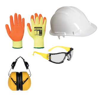

Impact resistant gloves
Helmet
Ear plugs
Safety glasses
Safety shoes
Transportation
System components
System components come in one box which includes: batteries, battery nutrunner, click wrench, hoses and hand controller (PFHC).
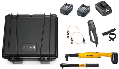
Before sending tools onsite, check that the following is done:
Batteries are charged
Click wrench is set to 75 Nm
Nutrunner is adjusted to max torque and medium speed.
Tensioner
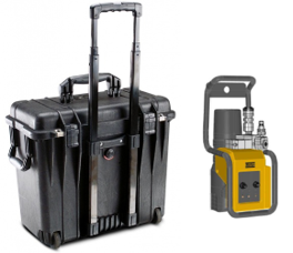
Tensioner is supplied as a kit with a frame installed in an individual box and it includes a pressure test and calibration certificates.
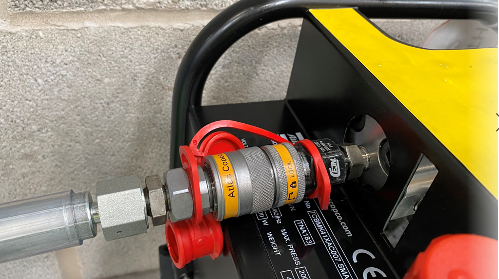
Keep the connector protection caps always connected when the tensioner is not in use.
Hydraulic pump/power pack
The pump is supplied without oil and has two caps, red and black. The red cap should be used when the pump is in use, and when the pump is being transported use the black cap.


Make sure to use the right grade of oil as per ambient temperature. Only ISO VG oil with high viscosity index over 140 is permitted.
Pre-Installation Checks
This chapter is a general description of pre-installation checks that needs to be done on the SP2000 pump in order to ensure its continued use.
In case of any concerns about the standard of the equipment or the information in this document, please contact the local Atlas Copco sales representative.
Hydraulic connection
Check the main quick disconnect hydraulic outlet for any dirt ingress. Any ingress must be carefully removed. In case of any concerns about its condition or operation, replace the main quick disconnect hydraulic outlet.
Check that the locking ring functions correctly.
Check the main hydraulic connection for correct connection and operation to a mating connection. If the connection is difficult to make up, or remove, replace the main hydraulic connection.
Hydraulic gauge
Check that the needle on hydraulic gauge reads zero when the hydraulic pump pressure is zero. In case of any doubt about its operation, re-calibrate or replace the hydraulic gauge.
If the front glass is cracked, or if glycerin is leaking, or has leaked, replace the gauge.
Electrical plug socket and cable
The cable must be free from any cuts or tears. No wires should be exposed along its length.
The cable must be securely connected at each end to the pump unit and plug.
In case of any concerns about the security of the cable, or plug socket, replaced the cable or the plug socket.
Communication cable connections
The connections must be secure to the electrical enclosure, without any wiring exposed.
The cable must be free from any cuts or tears. No wires should be exposed along its length.
Oil filler cap
When the pump is in use, use the orange filler cap. The orange cap is breathable allowing air to escape and to eradicate any pressure build up within the oil reservoir.
When the pump is not in use, or when it is transported, use the black filler cap. The black cap is a blanking cap that seals off the oil filling tube and prevents oil spillage.
Frame
Wiping the frame down occasionally can help in identifying any issues.
The hoisting point at the rear of the frame must be without corrosion.
The hoisting point must move freely.
The hoisting point must be secure in its position.
Motor / Powerpack
A general periodic wiping down of the powerpack will help in identifying any issues.
It is extremely important to use the correct grade of oil in order to protect the internal pumping elements of the powerpack.
It is advisable to indicate the oil type/grade that is used by adding an identification label to the assembly.
Do not tamper with the high pressure relief valve and make sure that it has the locking wire in place, see the picture below. The high pressure relief valve is the safety protection valve that prevents the powerpack from being over pressurized.
Point and click on image to see more information:1
The locking wire must be in place
Hoses
See Safety Instructions for Hydraulic Hoses. Printed Matter number is 98392524.
Installation Instructions
Unpack the tensioner, hose and system cables from the respective boxes.
Check the pump oil level and power specifications. The required power to be connected is 400V, 50/60 Hz, 3 phase.

The system will not start if the oil level is below the minimum level mark. It triggers the Pump motor oil level low alarm.
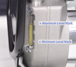
Top up oil and make sure that the in-use red cap is on the mouthpiece of the oil inlet. Do not use the pump with the black cap on as it can choke the system leading to no pressure built up.

SP2000, 400V is a 3 phase pump. When starting it the first time, no pressure is built if phases are reversed.
Connect one side of the hose to the pump and the other side to the tensioner. Secure the joint with locking rings.

Locking ring on hydraulic coupling Connect the system cables, use one system cable to connect the pump with the tensioner and the other to connect the pump with the hand controller.

Hand controller can be connected with system cables to the pump or to the tensioner.


Engage battery nutrunner on to the square drive at the top of the tensioner's head. The nutrunner is set at 30 Nm and an optimum speed for proper operation for all sizes of tensioners.


Check the battery charge level. The tensioner cannot rundown or be de-mounted after tensioning if the battery level is too low.
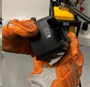

Do not remove the ring shaped holder from the frame. It supports the battery nutrunner.
Engage the click wrench on the tensioner. The click wrench is pre-set at 75 Nm from the warehouse. It should not be changed or set on site.
-
Before placing the tensioner on the top of the bolt, check the following:
The system is building pressure in manual mode at 200 bar.
The bolt protrusion is as per guide plate provided in the kit. Minimum bolt protrusion must be equal to the 1 x D of the bolt. If bolt protrusion is below the minimum, the tensioner can cause serious personal injury.
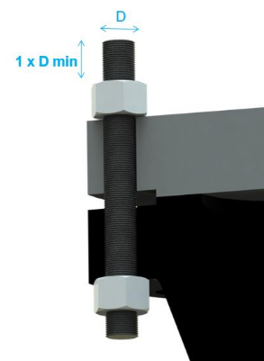
Bolts are pre-tightened to a minimum required torque/load. For more information, contact Atlas Copco representatives.
Bolt threads and nut are lubricated.
Rundown the tensioner straight on top of the bolt while keeping clear from the wall. Make sure that the base of the tensioner touches flat the flange. Make sure it is not inclined or rocking on the top of the flange. Avoid uneven gaps as shown on the picture.
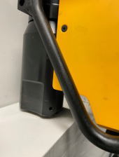

Take corrective actions to ensure smooth rundown every time, as misaligned flanges or inclined bolts can lead to load losses in joint.

Never use any other nutrunner or drive than the ones supplied with equipment.

Do not push hard to rotate the puller bar or the nut to achieve snug.
When the screen on the hand controller lights up and the Tasks menu is highlighted, the system is ready to use.
Check the status of connected device in the Connected Devices menu.
Check the number of tensioning cycles on the Puller Bar Count before maintenance or replacement. The maximum number of tensioning cycles is 5000.
Select the required program and follow the instructions at the bottom of the screen.
Operation
Configuration Instructions
Manual Mode
On the Tasks tab on the hand controller, select Manual mode, then set pressure in the Set Target Pressure. Accept to start the pump.
Start building pressure by pressing the pressurize button. Press and hold.
Tighten the nut while holding the pressurize button pressed until all LEDs are green and then release the pressurize button.
Use manual mode for tensioning in the following cases:
To initially check if the system is working and building pressure. Do not perform the phase Check Cycle at higher than 200 bar pressure.
De-tensioning the nut.
De-tensioning the nut
Turn back the tensioner by 3 mm from the face contact of flange.
Select Manual mode on the hand controller, then set pressure at which bolt was tensioned originally and start building pressure while holding the click wrench with positive force in counterclockwise direction.
When the applied load reaches break opening point, the click wrench moves freely opening the nut. Turn the click wrench 6-7 times its limited window cycle.
Release pressure and check that the bolt is loose.

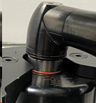
The max stroke indicator on the puller bar should not be visible while pressuring the tensioner. If visible, stop and adjust the position of the puller bar on bolt so that the max position is not reached until the required pressure is achieved. Otherwise, if done repeatedly, it can physically damage the internal components of the tensioner.

Batch Assembly Mode - Program 1
On the Tasks tab on the hand controller, select Batch assembly, then, select Program 1.
Scan the bar codes and accept it by pressing the forward button. There is an option for adding the bar codes manually by pressing the center button and selecting the manual input.
Enter batch count.
Select the bolt position number on the Position tool on bolt.
Start the program and follow the instructions at the bottom of the screen.
Installation phase
Press and hold the pressurize button on the hand controller until it stops building pressure.
Turn the nut clockwise.
Achieve torque by tightening the nut with the click wrench. When the torque is achieved all 3 LEDs will turn green. .
Release force on the click wrench.
Make sure the click wrench does not move in counterclockwise direction. When torque position is achieved, hold the click wrench for 0.3 seconds.
Pressurization phase
Press the pressurize button on the hand controller.
Rotate the click wrench gently.
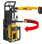
When the pressure reaches the set pressure, rotate the click wrench while holding the pressurize button until all LED's are green.
Do not make any aggressive movements or over torque with the click wrench. This will damage the internal components and the sensors.
Pressure release
This manual pressure release is optional since it is also possible to configure an automatic pressure release.
Press the de-pressurize button.
If the hand controller shows OK, press the forward right button on the keypad to go to the next bolt.
If the hand controller shows NOK, go back by pressing the left button on the keypad, select Position tool on bolt, and start initialization phase again.
Try for five times, and if it is still NOK, change the bolt or check the conditions of the joint.
Repeating aggressive click wrench tightening to achieve required torque and angle will damage internal components of the tensioner permanently.
Check that the puller bar is completely closed before starting the next bolt cycle.
Batch Assembly Mode - Program 2
Program 2 is optional and specific for particular applications.
On the Tasks tab on the hand controller, select Batch assembly, then select Program 2.
Scan the bar codes and accept it by pressing the forward button. There is an option for adding the bar codes manually by pressing the center button and selecting the manual input.
Enter batch count, then select the bolt position number on Position tool on bolt.
Start the program and follow the instructions at the bottom of the screen.
Follow the same procedure as for Batch assembly mode - First pass: Installation phase, Pressurization phase with nut rotation, and Pressure release.
When program 2 is completed on all bolts, batch will end and the main screen will appear. At this stage a report from the system can be generated.
Generating Report
Open the side cover on the hand controller to expose USB port.
Connect an empty USB memory drive.
Select Reports, then select Start generation. Wait for the message about the generated report to appear on the screen. Now the report in xml format is saved on the USB memory drive.
Remove the USB memory drive.
Service Mode
Service mode is used for periodical service operations.
Preparation
Mark the number of bolts to be tested.
Make sure the threads are clean from the rust and lubricated.
Rundown the tensioner on the bolt threads until it touches down the flange.
On the Tasks tab on the hand controller, select Batch Bolt service, then Bolt Service. Scan the bar codes and accept it by pressing the forward button. For exapleScan Tower Section ID, Scan Bolt Data ID and Scan Operator ID, then add batch of bolts to be serviced, select bolt position on Position tool on bolt and start the program.
Installation
Press the pressurize button to install the tensioner.
Rotate the click wrench clockwise until all three LEDs on the tensioner or the hand controller are green.
Change the rotational direction on the click wrench to counterclockwise and rotate till all LEDs on the middle row are green.
Release hand from the click wrench and finger from the trigger before starting the next step.
Both clockwise and counterclockwise rotation must be done gently.
Pressurization
Press again the pressurize button and hold it till the pressure reaches the set pressure and all the LEDs in the first row are green.
Rotate the nut for minimum of 10 degree counterclockwise.
Change direction of the click wrench to clockwise and rotate gently until the minimum required torque is achieved.
Pressure release
When all parameters are within the set limits and all LEDs are green, pressure will be released automatically or manually depending on the chosen initial setup. A tightening OK or NOK message will appear on the screen of the hand controller to take further actions.
Move to the next bolt and repeat all the steps from Installation phase until the batch is completed.
Service
Maintenance Instructions
Safe Storage
When the work is finished, make sure the following is done:
The pressure is completely released from the tensioner which means it shows zero pressure on the hand controller and also on the analogue gauge of the pump.
Take a backup of all reports before leaving site.
The bar codes of the flange or other identifiers were scanned or noted related to the tightening results.
In case of no bar code is available, the manual bar code can be entered.
Mark the last completed bolt in case of a short break.
Disconnect the pump from the main supply during overnight.
Use the black cap on the pump inlet during transportation. It prevents oil from spilling during transit up and down the tower.
Always use the certified lifting point on the frame marked at the back of the tensioner.
Point and click on image to see more information:1
Certified lifting point
Cover the electronic connectors on the tensioner and the pump with dust caps.
Point and click on image to see more information:1
Electronic connectors covered with dust caps
Point and click on image to see more information:1
Electronic connector covered with dust cap
Change the pump oil if the ambient temperature changes or if the pump is left unused for more than 90 days.
Put all articles back in the respective boxes in the allocated positions.
Troubleshooting
Troubleshooting and Alarms
The tables below describe different situations, problems and alarms with corresponding possible cause and solutions. The alarms will show an alert with a code on the hand controller for taking corrective actions.
Alarm | Possible cause | Solution |
|---|---|---|
Pump motor oil temperature high alarm | Oil temperature inside the pump is above the permissible temperature due to different reasons: Continuous working | Leave the pump idle to let it cool down for few minutes. |
Oil quality | Check for contamination. Change the oil. | |
External temperature | Change the oil to appropriate grade. | |
Pump motor oil level low alarm | When the oil level inside the pump is below the minimum level, the system stops. | Top up oil in the pump to resume the work. |
Leakage in the system | Check for leakage in the system, then repair or replace. | |
Pump motor protection alarm | Heavy current or unusual power activity inside the motor. This alarm is triggered for safety of electronics and electrical parts connected to the motor. | Open the small front window on the pump. Reposition the black knob to I position resumes the power supply to the motor. If the error repeats, check the main electrical supply. |
Tool communication disturbance | Overcurrent flowing for an excessive period of time is the most common. This alarm is triggered for the safety of the electronics and electrical parts within the electrical enclosure. | Open the small front window on the pump. Rearm the circuit breaker to resume work. If the breaker keeps tripping within seconds of the rework, stop the work and take corrective actions.
|
An electrical short circuit. | ||
An electrical ground fault. |
Problem | Possible cause | Solution |
|---|---|---|
Tensioner stuck on the bolt after tensioning | Low charge level of the battery nutrunner. | Replace the battery of the nutrunner with a charged battery. |
No gap between the wall and the tensioner. | Check the wall clearance at the back of the tensioner. If no gap, de-tension the bolt by using the manual mode. | |
Hole alignment, lubrication and bolt threads. | Check also the hole alignment, lubrication and bolt threads. If any doubts, change the bolt and try again. | |
Tensioner does not run down on bolt | Bolt threads are damaged. | Replace the bolt. |
Bolt threads are not lubricated. | Lubricate bolt threads. | |
Debris inside the tensioner threads. | Remove debris from the threads with a wire brush. | |
Bolt protrusion exceeds the maximum limit. | Adjust the protrusion by loosening the bolt so that it does not exceed the maximum limit. | |
Pressure not building over 200 bar in the pump | Leakage on the pump. | Check for leakage on the pump or in the hydraulic line of the system. Check the oil level. Top up with oil if too low. Send the pump for maintenance or repair if the problem persists. |
Wrong grade of oil. | Make sure to use the right grade of oil. | |
Hard to disconnect hydraulic line coupler from the pump | The nipple on the hose is worn out. | Change nipples on the hose and tensioner as soon as it becomes sticky and harder to disconnect. |