Fixtured Tightening Module
Electric screwdriver
Declarations
Liability
Many events in the operating environment may affect the tightening process and shall require a validation of results. In compliance with applicable standards and/or regulations, we hereby require you to check the installed torque and rotational direction after any event that can influence the tightening result. Examples of such events include but are not limited to:
initial installation of the tooling system
change of part batch, bolt, screw batch, tool, software, configuration or environment
change of air- or electrical connections
change in line ergonomics, process, quality procedures or practices
changing of operator
any other change that influences the result of the tightening process
The check should:
Ensure that the joint conditions have not changed due to events of influence.
Be done after initial installation, maintenance or repair of the equipment.
Occur at least once per shift or at another suitable frequency.
Noise Declaration Statement
Sound pressure level < 74.4 dB(A) , uncertainty 3 dB(A), in accordance with ISO 15744.
Sound power level 71.7 dB(A) , uncertainty 3 dB(A), in accordance with ISO 15744.
These declared values were obtained by laboratory type testing in accordance with the stated standards and are suitable for comparison with the declared values of other tools tested in accordance with the same standards. These declared values are not adequate for use in risk assessments and values measured in individual work places may be higher. The actual exposure values and risk of harm experienced by an individual user are unique and depend upon the way the user works, the workpiece and the workstation design, as well upon the exposure time and the physical condition of the user.
We, , cannot be held liable for the consequences of using the declared values, instead of values reflecting the actual exposure, in an individual risk assessment in a work place situation over which we have no control.
We recommend a programme of health surveillance to detect early symptoms which may relate to noise exposure, so that management procedures can be modified to help prevent future impairment.
The noise emission is given as a guide to the machine-builder. Noise emission data for the complete machine should be given in the instruction manual for the machine.
Regional Requirements
Safety
DO NOT DISCARD - GIVE TO USER
Statement of Use
For professional use only.
This product and its accessories must not be modified in any way.
Do not use this product if it has been damaged.
If the product data or hazard warning signs on the product cease to be legible or become detached, replace without delay.
The product must only be installed, operated and serviced by qualified personnel in an industrial environment.
Safety Signal Words
The safety signal words Danger, Warning, Caution, and Notice have the following meanings:
DANGER | DANGER indicates a hazardous situation which, if not avoided, will result in death or serious injury. |
WARNING | WARNING indicates a hazardous situation which, if not avoided, could result in death or serious injury. |
CAUTION | CAUTION, used with the safety alert symbol, indicates a hazardous situation which, if not avoided, could result in minor or moderate injury. |
NOTICE | NOTICE is used to address practices not related to personal injury. |
Product Specific Instructions
Installation
General Installation Safety
Always make sure that the drive unit/controller is switched off before connecting/disconnecting the tool cable.
Always disconnect the tool from the drive unit/controller before making any adjustments on or inside the tool.
The tool with its drive/controller box is designed to operate at any setting within its torque range at a primary voltage of nominal 230V/ 50Hz alternatively 115V/ 60Hz, single phase. Refer to the manual for the drive unit or controller.
Make sure that the tool is in good working order and that the controller is correctly programmed before use to avoid unexpected behavior from the tool which may result in operator injury.
Additional Installation Safety Messages
Operation
General Operation Safety
Due to entanglement risk, do not wear gloves.
Be prepared of the reaction force which will occur when the tool is used.
This product is only intended for industrial use and shall only be operated indoor in dry rooms. This product must not be used in explosive atmospheres.
Only use power sockets.
When using a suspension yoke, make sure that it is in good condition and correctly fastened.
Be prepared of the reaction force which will occur when the tool is used.
Make sure that the tool is in good working order and that the controller is correctly programmed before use to avoid unexpected behavior from the tool which may result in operator injury.
Be aware of the rotational direction of the spindle before starting the tool, the reaction force may work in an unexpected direction with risk of crush injuries.
The tool with its drive/controller box is designed to operate at any setting within its torque range at a primary voltage of nominal 230V/ 50Hz alternatively 115V/ 60Hz, single phase. Refer to the manual for drive unit.
Always keep the drive unit/controller locked.
The tool is intended for intermittent use. A typical operating cycle is 1 s on, 4 s off. This may vary substantially depending on the application. The acceptable duty cycle depends on many factors including torque and joint type. The tool contains protective mechanisms that ensure that the acceptable duty cycle is not exceeded.
Avoid using tightening strategies in applications outside their limitations.
Major changes in joint characteristics will affect the operator reaction force.
Consider that a joint failure or a tool error can cause sudden unexpected reaction force and possibly injure the operator.
Recommended value for Rundown Complete is 10% of target torque.
The product must only be operated by qualified person in an industrial assembly environment. Make sure that the tool bit does not come in contact with the conductors in the controller cord, or any other concealed conductors or live electrical parts.
Additional Operation Safety Messages
Service and Maintenance
Additional Maintainance Safety Messages
General Service and Maintenance Safety
Always keep the controller switched off during service in order to avoid unexpected start-up.
The product must only be installed, operated and serviced by qualified personnel in an industrial environment.
Cleaning Instruction
Equipment should be wiped off with a damp/wetted cloth.
Only use water, no cleaners containing solvents should be used.
Contact your Atlas Copco service technician for cleaning advice as per current recommendations and for your particular tool.
Regular Cable Inspections
Regularly inspect the power cable and the tool cable. If the cables show any sign of damage, replace them.
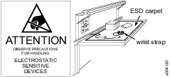
Preventing ESD Problems
The components inside the product and controller are sensitive to electrostatic discharge. To avoid future malfunction, make sure that service and maintenance is carried out in an ESD approved work environment. The figure below shows an example of an appropriate service work station.
Signs and Stickers
The product is fitted with signs and stickers containing important information about personal safety and product maintenance. The signs and stickers shall always be easy to read. New signs and stickers can be ordered by using the spare parts list.

Country of Origin
For the Country of Origin, please refer to the information on the product label.
Intended use of the Fixtured Tightening Module
This product is designed to feed and hold the screws in position and apply the specified Torque to the joint in an automated process. The tightening process is controlled by the Power Focus 6000. No other use is permitted.
The partly completed machine is a fixtured screw feeding system intended for producing screw connections. The screw feeding is proceeded automatically by a Screw Feeding Unit. The Fixtured Screw Feeding Tightening Module and the Screw Feeding Unit are powered and controlled by the Power Focus 6000 and customer PLC (Programmable Logic Controller).
The tightening module should be used only indoors.
The tightening module should be put into operation only with the system components described here.
Permitted use of the Fixtured Tightening Module components
Fixtured Tightening Module and Driving Tool - Requires a defined torque or a defined angle of rotation.
Cables (electrical) - Provides electrical supply and controls the screw fastening system.
Hoses (pneumatic) - Supplies the Fixtured Tightening Module with pneumatic energy from the Screw Feeding Unit.
Feeding Tube - Transports fasteners from the Screw Feeding Unit to the feeding head.
Power Focus 6000 - Controls and monitors the screw fastening process.
Screw Feeding Unit - Feeds the Fixtured Tightening Module with screws.
Publication Information
Publication Version | Software Version | Revision Date | Change Description |
1.0 | No software chapter has been included | First version 14-06-2022 | None |
Warranty
Product warranty will expire 12+1 months after dispatch from 's Distribution Center.
Normal wear and tear on parts is not included within the warranty.
Normal wear and tear is that which requires a part change or other adjustment/overhaul during standard tools maintenance typical for that period (expressed in time, operation hours or otherwise).
The product warranty relies on the correct use, maintenance, and repair of the tool and its component parts.
Damage to parts that occurs as a result of inadequate maintenance or performed by parties other than or their Certified Service Partners during the warranty period is not covered by the warranty.
To avoid damage or destruction of tool parts, service the tool according to the recommended maintenance schedules and follow the correct instructions.
Warranty repairs are only performed in workshops or by Certified Service Partners.
offers extended warranty and state of the art preventive maintenance through its contracts. For further information contact your local Service representative.
For electrical motors:
Warranty will only apply when the electric motor has not been opened.
General Data Protection Regulation (GDPR)
This product offers the possibility to process personal identifiable information such as system user name, role and IP-address. The purpose of this processing capability could be to enhance quality control through traceability and proper access management.
If you decide to process personal data you need to be aware of and comply with relevant personal data protection rules, including, in the EU the GDPR as well as other applicable laws, directives and regulations. Atlas Copco can in no way be held liable for any use made by you of the product.
Packaging and Storage
Packaging
The packaging is intended to protect the individual components from transport damage, corrosion, and other damage during transport until assembly. The packaging must not be damaged under any circumstances and should only be removed immediately before assembly.
Storage
The devices and, if necessary, spare parts should be stored in a packaged condition, which provides further protection against environmental influences. The following conditions for storage must be observed.
Never store outdoors - not even for a short time.
The components should be stored in a dry place, and should be protected from dust and aggressive media.
Protect from sunlight.
Avoid mechanical vibration.
Storage temperature: + 10 ° C to + 55 ° C. High variations of temperature should be avoided.
Relative humidity: 5% to 95% (not condensing).
If the device is stored for longer than a month, the condition of all parts and the packaging should be checked regularly, if necessary, refresh/renew the preservation.
Where to find information
The Fixtured Tightening Module User Guide contains all information about the product, including the following:
Safety
System Description
Installation
Operation
Maintenance
Troubleshooting
The Safety chapter contains important safety information. You must read the safety instructions before operating the Fixtured Tightening Module.
The System Description chapter describes different parts of the Fixtured Tightening Module and also the main components and connections of the entire Fixtured Screw Feeding System.
The Installation chapter describes mounting procedures, installation workflow, and cable management.
The Operation chapter describes the operating sequences of the Fixtured Tightening Module.
The Maintenance chapter helps you to maintain the different parts of the Fixtured Tightening Module and also provides information on the maintenance schedule and the respective tightening torques.
The Troubleshooting chapter helps you to troubleshoot the most common issues.
System Description
The Fixtured Screw Feeding System consists of the Fixtured Tightening Module, Driving Tool, Power Focus 6000, Feeder, external Valve Control Unit, cables, and hoses. It is part of Atlas Copco’s Smart Connected Assembly concept and supports industrial production environments to become more efficient, ergonomic, and maximize the production output.
Fixtured Tightening Module
The Fixtured Tightening Module carries out the automatic feeding process. It consists of the following parts:
Feeding Head
Head-stroke and Bit-stroke version for fixed stations
Bit-stroke version for robot/cobot
The Fixtured Tightening Module components and functions are explained in the table below:

No | Components | Functions |
1 | Bit | Transmits the Torque to the screw. |
2 | Aligning Jaws | Guides the air-blown screw during the screw tightening process. The Aligning Jaws are connected to their holders with tension pins. The spring in the holders closes the Aligning Jaws. |
3 | Swivel Arm | Holds and loads the next screw while the previous screw is being tightened. The Swivel Arm guides the air-blown screws into the Aligning Jaws of the Feeding Head while it is in the loading position. In the working position, the Swivel Arm is swirled out by the Bit movement. |
4 | Feeding Head (in blue color) | Receives the screws through the swivel arm. The Aligning Jaws attached to the jaw holders, and thereby the feeding head guide the shift, and hold the screw in place for the bit to engage. |
5 | Swivel Arm Holder | Holds the Swivel Arm. |
6 | Quick-change Coupling | Helps to change the Feeding Head and Bit Assembly. |
7 | Feeding Tube Connector | Connects the Feeding Tube. |
8 | Sleeve | Helps to change the angle positions of the Feeding Head. Using these screws, the angle positions of the Feeding Head can be changed in -45°, -90°, 0°, 45°, and 90° degrees. Refer to the Angle Positions of the Feeding Head image below the table. |
9 | Feeding Tube | Transports the screws from the Screw Feeding Unit to the Swivel Arm by the pressurized air. |
10 | Ring Sensor | Detects the screw at the end of the Feeding Tube. |
11 | Inductive Sensor | Detects whether the Bit is completely retracted. |
12 | Stroke Position Sensor | Detects the position of the Bit-stroke. |
Bit-stroke version
The Bit-stroke only allows movement of the Bit in the front to push the screw through the jaws. It is used and mounted on robots or Cartesian slides that provide the Z-axis motion to the part.

Description | Value |
Total weight including QST34 Driving Tool | 4.3 kg |
Total weight without Driving Tool | 4.3 kg – 2 kg = 2.3 kg |
Maximum Torque of the Screw Feeding Head | 10 Nm |
Head-stroke version
The Head-stroke provides additional axis movement to bring the Feeding Head closer towards the tightening location. Thereby, the motor stays stationary and only the Feeding Head moves. It is used and mounted in stand-alone cell assembly and palletized assembly lines.

Description | Value |
Head-stroke | 48 mm |
Total weight including QST34 Driving Tool | 6 kg |
Total weight without Driving Tool | 6 kg - 2 kg = 4 kg |
Maximum Torque of the Feeding Head | 10 Nm |
Driving Tool
The Driving Tool generates the rotary motion and provides Torque which is transmitted to the Feeding Head via the Drive Shaft.

No. | Component | Function |
1 | Drive Shaft | Geared shaft of the rotary drive |
The different part numbers, model numbers, torque range, and speed of fixtured driving tools are specified in the below table:
Part Number | Model Number | Torque Range (Nm) | Speed (rpm) |
8434320084 | ETF SL21-01-226-SF | 0.3-1.2 | 3000 |
8434320085 | ETF SL21-04-226-SF | 0.8-4 | 1600 |
8434320086 | ETF SL21-07-226-SF | 1.5-7.5 | 970 |
8434320087 | ETF SL21-10-226-SF | 2-10 | 720 |
8434320088 | ETF SL21-01-256-SF | 0.3-1.2 | 3000 |
8434320089 | ETF SL21-04-256-SF | 0.8-4 | 1600 |
8434320090 | ETF SL21-07-256-SF | 1.5-7.5 | 970 |
8434320091 | ETF SL21-10-256-SF | 2-10 | 720 |
Part Number | Model Number | Torque Range (Nm) | Speed (rpm) |
4028001007 | QST34-20CT-SF-226 | 4 - 20 | 1000 |
4028001016 | QST34-20CT-SF-256 | 4 - 20 | 1000 |
4028001017 | QST34-20CTTA-SF-226 | 4 - 20 | 1000 |
4028001022 | QST34-20CTTA-SF-256 | 4 - 20 | 1000 |
4028001014 | QST34-8CT-SF-226 | 2 - 8 | 3000 |
4028001015 | QST34-8CT-SF-256 | 2 - 8 | 3000 |
4028001020 | QST34-8CTTA-SF-226 | 2 - 8 | 3000 |
4028001021 | QST34-8CTTA-SF-256 | 2 - 8 | 3000 |
Main Components of the Fixtured Screw Feeding System
The individual components or the system composition can be customer specific, and may therefore differ from the components shown here.
The Fixtured Screw Feeding System consists of the following main components (Bit-stroke):

No. | Components | Functions |
1 | Screw Feeding Tightening Module
| To carry out the tightening process. |
2 | Power Focus 6000 | To control and monitor the screw tightening process. |
3 | Screw Feeding Unit | To transport, sort, separate, and feed the screws into the Fixtured Tightening Module using compressed air. |
4 | Valve Control Unit | To control the electrical connections and pneumatic connections including the valves and fieldbus. |
5 | Tool Cable | Electrical connection between the Power Focus 6000 and the Fixtured Tightening Module |
6 | Air Connection | Air supply for the Valve Control Unit driven by the Screw Feeding Unit. |
7 | Air Connection | Air Connection for Forward and Return Bit Stroke between the Fixtured Tightening Module and the Valve Control Unit. |
8 | Connection Cable | Electrical connection between the Power Focus 6000 and the Screw Feeding Unit. Once the Power Focus 6000 is switched ON, the screw feeding unit gets an activation signal. |
9 | Fieldbus Connection | Electrical connection between the Power Focus 6000 and the Screw Feeding Unit. |
10 | Feeding Tube | Pneumatic transport of screws from the Screw Feeding Unit to the Fixtured Tightening Module |
11 | Signal Line | Communication between the Screw Feeding Unit and the Valve Control Unit. |
12 | Signal Line | Electrical connection between the Fixtured Tightening Module and the Valve Control Unit. The ring sensor detects the screws at the end of the Feeding Tube. |
13 | Signal Line | Electrical connection between the Fixtured Tightening Module and the Valve Control Unit. The inductive sensor is for the Bit-stroke retracted position. |
The Fixtured Screw Feeding System consists of the following main components (Head-stroke):

No. | Components | Functions |
1 | Fixtured Tightening Module
| To carry out the tightening process. |
2 | Power Focus 6000 | To control and monitor the screw tightening process. |
3 | Screw Feeding Unit | To transport, sort, separate, and feed the screws into the Fixtured Tightening Module using compressed air. |
4 | Valve Control Unit | To control the pneumatic and electrical connections. For example, Bit-stroke and Head-stroke. |
5 | Tool Cable | Electrical connection between the Power Focus 6000 and the Fixtured Tightening Module. |
6 | Air Connection | Air supply for the Valve Control Unit driven by Screw Feeding Unit. |
7 | Air Connection | Air Connection for Forward and Return Bit-stroke and Head-stroke between the Fixtured Tightening Module and the Valve Control Unit. |
8 | Connection Cable | Electrical connection between the Power Focus 6000 and the Screw Feeding Unit. Once the Power Focus 6000 is switched ON, the screw feeding unit gets an activation signal. |
9 | Fieldbus Connection | Electrical connection between the Power Focus 6000 and the Screw Feeding Unit. |
10 | Feeding Tube | Pneumatic transport of screws from the Screw Feeding Unit to the Fixtured Tightening Module. |
11 | Signal Line | Communication between the Screw Feeding Unit and the Valve Control Unit. |
12 | Signal Line | Electrical connection between the Fixtured Tightening Module and the Valve Control Unit. The ring sensor detects the screws at the end of the Feeding Tube. |
13 | Signal Line | Electrical connection between the Fixtured Tightening Module and the Valve Control Unit. The inductive sensor is for the Head-stroke retracted position. |
14 | Signal Line | Electrical connection between the Fixtured Tightening Module and the Valve Control Unit. The inductive sensor is for the Head-stroke extended position. |
15 | Signal Line | Electrical connection between the Fixtured Tightening Module and the Valve Control Unit. The inductive sensor is for the Head-stroke retracted position. |
For more information about the Screw Feeding Unit, see product information of the Screw Feeding Unit.
For more information about the Power Focus 6000, see product information of the Power Focus 6000.
Installation Instructions
Installation
This chapter provides installation instructions of the Fixtured Tightening Module.
Please read all the below safety messages before installation.
Mounting the Fixtured Tightening Module
Mount the Fixtured Tightening Module using the below mounting plate. Mounting is possible on a robotic device or a frame.

Position | Dimension | Tightening Torque |
1 | 4 DIN 912 M6X18 | 10 Nm |
2 | 2 ISO 8734 - D6X16 pin | Press the pin |
3 | 2 DIN 6 912 M8X20 | 25 Nm |
The four center screws DIN 912 M6X18 with threads are used to mount the mounting plate on the intended location. The tightening torque should be 10 Nm. It is possible to mount the mounting plate either from the front side or from the back side using the four center screws with threads.
From the your side, the two pins ISO 8734 - D6X16 in the distance of 4-10mm should be used to align the mounting plate.
The two screws DIN 6 912 M8X20 on the left side shown in the above image are used to mount the Fixtured Tightening Module on the mounting plate. The tightening torque should be 25 Nm.
Reaction Force
Below is the reaction force needed for the bit-stroke version which has to be absorbed by the external fixture or other movable parts.
Bit-stroke Pressure | Static Reaction Force | Reaction Force including dynamic reserve |
4 bar | 200 N | 400 N |
5 bar | 240 N | 440 N |
6 bar | 290 N | 490 N |
When a new head-stroke function is added, the bit-stroke force must not exceed the head-stroke force.
Mounting the Feeding Tube with the adapter

Positions | Components |
1 | Fork Pressure Plate |
2 | Feeding Tube Connector |
3 | Feeding Tube |
Angle Positions of the Feeding Head
Through the Feeding Tube, the screws are transported by pressurized air from the Screw Feeding Unit to the Swivel Arm of the Fixtured Tightening Module. The Feeding Tube connector is clamped with a fork pressure plate onto the holder. The pressure plate is fixed with two M4x8 Allen screws (M4 = 3 Nm). The position of the feeding head can be adjusted to meet the accessibility of the application.

Orientation of Air Connections
The Orientation of air connections is project specific.


Installation Workflow
Connect the Driving Tool to the tightening controller.
Connect the Feeding tube to the Fixtured Tightening Module.
Connect all the sensor cables and pneumatic lines to the Valve Control Unit.
Connect the Valve Control Unit to the Feeder with the pneumatic supply cable.
Refer Main Components chapter
Cable and Feeding Tube Management
Fitting of the Tool Cable
Make sure that the tool cable is of correct type.
Align the cable connector using the two asymmetrically positioned heads on the connector to fit in the slots in the tool handle.
Tighten the lock nut.
Make sure that the connection is correct by pulling, pushing, and turning the cable connector (there should be no movement).
The tool has a built in electronic memory chip that will transmit the torque transducer calibration value and angle pulses to the POWER FOCUS/drive unit. Any changes made of these values in the POWER FOCUS while the tool is connected will be stored in the tool memory.
Cable and Feeding Tube Management
The below table specifies the inner diameter, outer diameter, and bending radius of the feeding hose.
Inner diameter (mm) | Outer diameter (mm) | Bending radius (mm) |
7 (0/+0,50) | 13+-0,3 | 425 |
7,5 (0/+0,50) | 14+-0,3 | 425 |
8 (0/+0,50) | 15+-0,3 | 425 |
8,5 (0/+0,50) | 16+-0,3 | 425 |
9 (0/+0,50) | 16+-0,3 | 425 |
10 (0/+0,50) | 18+-0,4 | 425 |
11 (0/+0,50) | 19+-0,4 | 425 |
12 (0/+0,50) | 19+-0,4 | 425 |
13 (0/+0,50) | 20+-0,4 | 425 |
14 (0/+0,50) | 21+-0,4 | 425 |
15 (0/+0,50) | 22+-0,4 | 425 |
16 (0/+0,50) | 23+-0,4 | 425 |
Fixing cables and Feeding Tubes
Follow the below instructions while fixing cables and feeding tubes:
Never use cable ties or zip ties for attaching the feeding hose and tool cable. Instead, use Velcro fasteners.
Avoid over-tightening the feeding hose and cable. It causes entanglement and the fastener gets stuck in the hose.
For more information about correct cable management and best practices, please refer to the Cable Management pocket guide (Part No. 9833 1640 01).
Operation
In this section, you can find step-by-step information about how to operate the product.
Operation
In this chapter, the operational safety instructions, general instructions for the operator, and the workflow of the module are described.
Please read the below safety instructions before Operation.
General Instructions for the Operator
Make sure you are familiar with the operator’s instructions before you use this tool.
The tool together with any attachments or accessories, must never be used for anything other than the designed purpose.
All locally legislated safety rules regarding installation, operation, and maintenance shall be respected at all times.
This product is only intended for industrial use and shall only be operated indoor in dry rooms. This product must not be used in explosive atmospheres.
Keep hands, long hair, and other objects away from the rotating socket.
Make sure that the tool is in good working order and that the controller is correctly programmed before use to avoid unexpected behaviour from the tool which may result in operator injury.
Do not use force when handling the Screw Feeding Tightening Module.
Use only accessories recommended by the manufacturer. The connection of unsuitable accessories is a potential source of danger.
Check the Screw Feeding Tightening Module for any incorrect adjustments, jammed moving parts, damage, and other faults that could affect the operation of the device.
Operating Sequences
The two different operating sequences of the Fixtured Tightening Module are described below:
No. | Operating Sequence |
1 | Bit-stroke |
2 | Bit and Head-stroke |
Bit-stroke Operating Sequence
The operation gets triggered by an external control unit or PLC (Programmable logic controller).
The Bit-stroke moves forward with the Bit rotation and pushes the Swivel Arm out of the Feeding Head. When the swivel arm is pushed out, it allows to reload the next screw.
The Bit-stroke pushes the screws out of the Aligning Jaws during the tightening process.
The tightening process gets completed.
The Bit-stroke moves backward to the loading position.
The next screw gets carried from the Swivel Arm into the Aligning Jaws.
Bit and Head-stroke Operating Sequence
The operation gets triggered by an external control unit or PLC (Programmable logic controller).
The Head-stroke moves forward from the idle position to the working position.
The Bit-stroke moves forward with the Bit rotation and pushes the Swivel Arm out of the Feeding Head. When the swivel arm is pushed out, it allows to reload the next screw.
The Bit-stroke pushes the screws out of the Aligning Jaws during the tightening process.
The Bit-stroke and the Head-stroke move backward to the idle position.
The tightening process gets completed.
The Bit-stroke moves backward to the loading position.
The next screw gets carried from the Swivel Arm into the Aligning Jaws.
Maintenance Instructions
Service Recommendations
Preventive maintenance is recommended at regular intervals. See the detailed information on preventive maintenance. If the product is not working properly, take it out of service and inspect it.
If no detailed information about preventive maintenance is included, follow these general guidelines:
Clean appropriate parts accurately
Replace any defective or worn parts
Tools and Mounting Devices
Required Standard Tools and Specifications
No. | Tools | Specifications |
1 | Allen key | 1,5; 2, 2,5; 3; 4; 5; 6; 7; 8; 9; 10 (mm) |
2 | Wrench | 5; 7; 8; 10; 13; 14; 17; 19; 22; 24; 26 (mm) |
3 | Screw Driver | Set of Screw Drivers |
4 | Diagonal Cutter | |
5 | Torque Wrench | Up to 50 Nm |
6 | Grease Gun | For guide block greasing |
7 | Hot Air Gun | T=130°C |
8 | Tube cutting tool | 4 to 35 mm |
Required Mounting Devices and Description
Mounting Devices | Description |
Adjustable Hook Wrench | Tool for changing the Bit adaptor, Bit, and union nut of the stroke module. |
Alignment Jaw Fixture | Device for fixing the tension pins with which fasten the alignment jaws to the holder. There are 2 holders and 2 mounting sides for the alignment jaws with different sizes:
|
Pin Punch | Tool for dismounting the tension pins which hold the alignment jaws in the holders. |
Holder with the spline | Holder with the spline is used to change the Bit. During Bit-change, the adaptor should be clamped securely. |


Maintenance Schedule
Warranty claims can only be asserted if the listed maintenance work has been carried out regularly and carefully at the specified intervals by trained personnel.
Maintenance Intervals
The below table specifies the maintenance intervals, how to do the maintenance check, and the responsible trained personnel who does the maintenance check:
Intervals | Maintenance check | Personnel |
Daily | Visual inspection and clean the system | Operator |
Monthly (or 100.000 Cycles) | Check and clean the system | Maintenance Expert |
Yearly (or 1.000.000 cycles) | Check and clean the system | Maintenance Expert |
Daily Maintenance
The below daily maintenance table specifies the components and how to do the maintenance check. Refer to the numbers from the below image:


No. | Components | Maintenance check |
1 | Bit/Bit Adapter | Visual inspection |
2 | Alignment Jaws | Clean the adhesives or other adherent impurities. For example, adhesive coatings, screw lock residues, etc., |
3 | Feeding Head | Clean the adhesives or other adherent impurities. For example, adhesive coatings, screw lock residues, etc., |
4 | Swivel Arm | In case of wear ,defect, or extensive impurities replace it. |
5 | Lines and Hoses | Visual inspection. In case of wear, defect, or extensive impurities, replace it. |
Monthly Maintenance (or all 100,000 feeding cycles)
The below monthly maintenance table specifies the components and how to do the maintenance check:
No. | Components | Maintenance check |
1 | Bit/Bit Adapter | Visual inspection. In case of wear, defect, or extensive impurities, replace it. |
6 | Downholder | Check and replace the Downholder if worn out or difficult to move. |
7 | Tool cable | Check and replace, in case of wear and/or defect. |
8 | Signal lines to tightening module | Check and replace, in case of wear and/or defect. |
9 | Signal line to feeding unit | Check and replace, in case of wear and/or defect. |
10 | Feeding tube | Check if properly mounted. Replace, in case of wear and/or defect. |
Yearly Maintenance (or all 1,000,000 feeding cycles)
The below yearly maintenance table specifies the components and how to do the maintenance check:
No. | Components | Maintenance check |
All components from monthly Maintenance | Follow all the instructions from the monthly maintenance. | |
3 | Swivel Arm | Check and replace, in case of wear and/or defect. Tighten the loose screws, if needed |
11 | Stroke Rails/Carrier | Check and clean. Lubricate the rail carrier. |
12 | Driving Tool | See Product Information for QST34 or Tensor SL Maintenance interval and maintenance instruction |
Tightening Torques for Screws and Nuts
Improper work can result in serious damage to the device. Observe the specified tightening torques for any assembly, repair, or maintenance work. Use torque key and pay attention to the specified direction. All screws and screw connections which are screwed into pneumatic components must be tightened according to the manufacturer’s instructions with the specified tightening torque.
Tightening torques for metric screws
For mounting the joining tool the following specifications are recommended:
Utilization of elastic limit: 80%
Strength class: 8.8
Zinc-plated
The following values in the table are based on a friction coefficient of 0.12:
Nominal Diameter | M3 | M4 | M5 | M6 | M8 | M10 | M12 |
Tightening torque (Nm) | 1.2 | 3.0 | 6.0 | 10 | 25 | 49 | 85 |
Grease and Detergents
No. | Grease and Detergents | Description |
1 | Klüber Isoflex NBU 15 | Bearing block grease |
2 | Klübersynth 34-402 | Pressure-resistant lubricant for parts of the stroke cylinder |
3 | Klüber Paste 46MR401 | Multi-purpose High-pressure White Paste for drive shaft/spline |
4 | Ballistol Klever Ballistol Spray | Silicon-free spray oil |
5 | Industrial cleaner | Removes adhesive residues and other adherent residues |
Maintaining the Feeding Head
Removing and Replacing the Feeding Head
The Feeding Head needs to be repaired in case of damage. An inadequately maintained Feeding Head is a source of danger.
Follow the below steps to remove and replace the Feeding Head:
Push the Swivel Arm aside and pull the sleeve of the Quick-change Coupling backwards, and then pull off the Feeding Head (in blue color).
Attach the clean or the new Feeding Head and then release the sleeve of the Quick-change Coupling.
Make sure that the Feeding Head is correctly attached by turning and pulling it gently. The Feeding Head should remain attached to the tightening module.

Cleaning and Checking the Feeding Head
Clear the dirts of the Feeding Head using an industrial cleaner and a cloth.
Inspect the Feeding Head visually and check for damage. If damaged, the Feeding Head or the damaged components must be replaced.


Maintaining the Bit Assembly
Extending the Bit-stroke
To change the Bit, the extension of the Bit-stroke is required. There are two different ways to extend the Bit-stroke.
The rotary switch on the Atlas Copco screw feeder is used to enable the feeder's manual mode, which is then activated through the feeder's Human Machine Interface (HMI). In this way, the extension of the Bit command must be set in the HMI of the feeder.
In automatic mode, the Bit-stroke gets activated. In this way, the extension of the Bit command must be given through the client's line Programmable Logic Controller (PLC).

Removing the Bit Assembly
Remove the Feeding Head by pulling the Quick-change Coupling backward.

Pull the Bit Quick-change Coupling forward.
The Quick-change Coupling remains in an open position until the Bit Adaptor is pushed in again.
The Bit Assembly will pop out as soon the Bit Quick-change Coupling is pulled forward.
Cleaning and Checking the Bit Assembly
Clean the Bit Assembly and remove the residuals, if any.
Check the Bit Assembly completely. In case of any defect, the respective part must be exchanged.

Reinstall the Bit Assembly if there is no defect.
Insert the Bit Assembly into the sleeve with a slight twist until the toothing engages. The Bit Quick-change Coupling gets back to its position with a click sound.
Removing the Bit and Bit Adaptor
Removing the Bit from the Threaded Sleeve
There are two ways of removing the Bit from the Threaded Sleeve.
Hold the Threaded Sleeve with the Hook Wrench, and use pliers to unscrew the Bit from the Threaded Sleeve.
Another method is to clamp the Bit and unscrew the Threaded Sleeve with the Hook Wrench.
Perform step 1 in the reversed order to attach the new Bit to the Threaded Sleeve. Make sure that the Bit is not damaged during this procedure.
Make sure that the Bit, Threaded Sleeve, and new Bit Adaptor are correctly mounted together.
Insert the Bit Assembly into the Screw Feeding Front Part using the Bit Quick-change Coupling.

Positions | Components |
1 | Hook Wrench |
2 | Threaded Sleeve |
3 | Mounting Tool |
4 | Bit Adaptor |
5 | Bit |
Removing the Bit Adaptor
Hold the Threaded Sleeve with the Hook Wrench and make sure the hooks are into the holes.
Use the Mounting Tool to grip the Bit Adaptor and release it from the Threaded Sleeve.
Tightening Torque Specifications
Dimension | Tightening Torque (Nm) |
M4 | 3 |
M5 | 6 |
M6 | 10 |
M8 | 25 |
Replacing the Alignment Jaws
Follow the below steps to replace the Alignment Jaws.
The Alignment Jaws must be replaced in case of wear or damage.

Disassemble the Feeding Head by releasing the clamps and removing the stud.
Replace the Alignment Jaws and assemble the Feeding Head.
Using the alignment jaw device and the pin punch to drive the pins out.

Replace the front part of the alignment jaws and use the alignment jaw device to hold the parts together when driving the pins back in.
Cleaning and Lubrication of the Stroke Rail Carriers
Follow the below instructions to clean and lubricate the stroke rail carriers:
Clean the stroke rails using a wipe and industry cleaner and remove all impurities.

Lubricate the rail carriers by using a grease gun filled with Klüber Isoflex NBU 15.
By moving the carrier, the lubricate nipples will become reachable for the grease gun.
Inject 3-5 strokes of the grease in all lubricant nipples and remove any leaked grease.


Maintaining the Driving Tool
Follow the below steps to maintain the Driving Tool:
For maintaining the tool, it has to be disassembled from the stroke unit.
Remove the screws on the adapter plate and pull the driving tool out.
The Driving Tool can now be maintained as described in the Tool´s product manual.
After maintaining the tool lubricate the drive shaft and assemble the driving tool to the stroke unit. For Lubrication of the drive shaft (1) use Klüber Paste 46MR401.
No. | Component | Function |
1 | Drive Shaft | Geared shaft of the rotary drive |
Troubleshooting and Service
This section provides assistance in troubleshooting problems, should they arise, and contains information to help you maintain and service the product.
Overheated Tool
With proper adjustment the tool can handle any normal line jobs that an operator sustains. What can cause overheating are combinations of some factors: torque above rated, too low speed, too long ramp time (motor has to give high torque for a long time), very high prevailing torque, very soft joints, short cycle time. To correct, look over speed, ramp time, tightening strategy. One stage and Ergoramp are most heat conserving when applicable. Please refer to the User Guide of your POWER FOCUS. If the above corrections are not enough, choose a tool of the next higher capacity.
Removal of Jammed Screws
Follow the below troubleshooting steps to remove the Jammed Screws:
Never use excessive force for removing the jammed screws.
By opening the Alignment Jaws or lifting the Swivel Arm up, the jammed screws comes out easily from the feeding head.
In case of timing issues, the screws get struck between the Bit and the down holder. Adjust the timing in the software of the Feeder. Find more information in the Screw Feeding Unit Manual.
To dislodge the jammed screws, the air supply should be turned OFF and the Feeding Head should be removed from the tightening module. This procedure eliminates force to the tool parts and the screws get easily removed.
Find more information in the chapter on Removing and Replacing the Feeding Head.
Driving Tool Failure
Follow the below steps to troubleshoot the Driving Tool.
Check if the tool cable is properly tightened on the driving tool and the tightening controller.
Verify if there are any damages to the cable, and replace it if needed.
Check Power Focus, adjustments, and tightening parameters.
Irregular Stroke Movements
Follow the below steps to troubleshoot the irregular stroke movements:
Check if the valves on the Fixtured Tightening Module are properly opened for sufficient air flow into the stroke cylinder.
Check if there are any clogged pneumatic pipes.
For further adjustment, please refer to the Screw Feeding unit Product Instruction for proper adjustment of air pressure and timing parameters.
Recycling
Environmental Regulations
When a product has served its purpose it has to be recycled properly. Dismantle the product and recycle the components in accordance with local legislation.
Batteries shall be taken care of by your national battery recovery organization.