Configuring I/O
I/O Diagnostics is used to troubleshoot external hardware and to test configuration. The operator is able to troubleshoot a station that is not behaving correctly. A station's behavior is not only defined by its software, hardware and configuration, but the combined state of all its inputs and outputs. Therefore it is often helpful to get an overview of input and output states. This can for example aid in finding the following problems:
Hardware malfunctions in the accessories (lamps/cables/buttons etc.)
Suspicion that inputs are not properly received from surrounding systems.
Suspicion that outputs are not properly sent to surrounding systems.
To access the I/O diagnose function:
Select a controller in the Plant structure workspace
 .
. Select virtual station
 in the Menu bar of the controller workspace.
The workspace area displays a list of virtual stations in the controller. The list is empty if no virtual stations have been created.
Double-click on a virtual station name to open an existing virtual station configuration or click Add to create a new one.
The workspace shows the menus, including Accessories assigned to that specific virtual station.
Select the check box
 for the device to be diagnosed. The device has to be in status Connected.
Select Diagnose.
The I/O diagnostics function provides the possibility to Monitor the incoming and outgoing signals, sent to and received from the selected device. It is also possible to manipulate the information via Forced mode.
I/O diagnostics can be used from:
Controller GUI
Web GUI
ToolsTalk
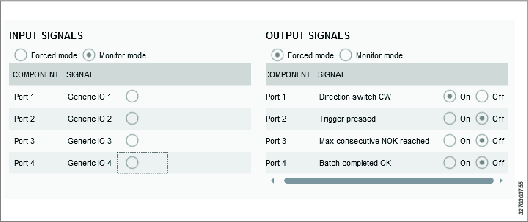
Diagnostics mode | Activate Monitor mode or Forced mode. Monitor mode: In monitoring mode it is possible to see status of all configured fields in the incoming and outgoing signals, sent to and received from the device. Whenever there is a change in a signal, the view is updated. Forced mode: When in forced mode, the signals are frozen in their current state and will be possible to manipulate from the client. The operator can now activate and deactivate signals individually. The change of signal value in forced mode is immediately propagated to the controller. When leaving forced mode all forced signals will be set to their actual values, that is, the values they would have had if no forcing had been performed. |
Component | The column Component lists the parts of the device where to connect the incoming/outgoing signals. |
Signal | List of signals configured for the selected device. If no signal is configured, the field displays the text "None". |
Only one diagnostics session can be active at a time and only one device at a time can be in diagnostics state. If the diagnostics is already in use, an information message is shown on the screen.


