Introduction
In this section, you can find the basic information about the product and also the formatting conventions used in the topics.
General Description
With the ILT, the wireless tool location solution by Atlas Copco, your battery tools will only operate in the correct area. Using wireless distance measurement technology, it tethers the tool to a specific workstation and disables the tool if it goes outside the set working range. This feature provides a virtual cable. Tool orientation detection continuously monitors the tool’s orientation. Users can define criteria for both roll and pitch angles, giving joint differentiation in certain applications.
Features
UWB radio technology with high precision
Tool-orientation detection
Integrated touch display
Communication via Open Protocol
Connect to Power Focus 4000
Connect to Power Focus 6000
Does not require ‘line of sight’
Tool tag accessories
Benefits
Enables flexible production
Simple and standalone installation
Easy to set up system and configure
Less down-time in production
Orientation functionality
Conventions
To enhance user understanding, certain formatting conventions are used throughout this document. The formatting conventions used are listed below.
Element | Notation | Description | Output |
|---|---|---|---|
General emphasis | In the Program workspace. | To make certain text elements stand out, or to highlight. | Text in Bold |
Graphical User Interface (GUI) items | Select the Function button. | Any reference to items found on screen in the GUI (for example, command buttons, icon names and field names). | Text in Bold |
Graphical User Interface (GUI) Path > | Generally, on the top of the GUI. | Navigation aid which keeps track of the location in the GUI. | For example: Controller > Program > Edit |
User input | Enter a Description for the program. | Any text input by the user. | Text in Bold |
File names | Enter a File Name for the export. | Files either exported from, or imported into the system. | Text in Bold Italic |
Variable and parameter names | Enter a Name for the export. | Variable and parameter names (not values). | Text in Italic |
Variable and parameter values | Enter a VALUE for the export. | Variable and parameter values. | Text in BOLD CAPS |
System output | Client.Domain.Models.ExportImportConfiguration | Any text output by the system. | Text in Monospace |
External links | Links to external sites that have information connected to the document or subject content. These could include:
| Selectable text to external sites | |
Internal documentation links |
If available, these links will be presented below the text. | Selectable text to internal content |
Revision history
Document Revision | Software Version | Software | Changes |
|---|---|---|---|
4 | 4.0.0 | ILT Base Station User Interface Software | New
|
3 | 3.0.0 | ILT Base Station User Interface Software | New
|
2 | 2.1.2 | ILT Base Station User Interface Software | New
|
2.0.2 | Radio Node Software | New
| |
1 | ILT Base Station User Interface Software | First edition | |
Radio Node Software | First edition |
General Data Protection Regulation (GDPR)
This product offers the possibility to process personal identifiable information such as system user name, role and IP-address. The purpose of this processing capability could be to enhance quality control through traceability and proper access management.
If you decide to process personal data you need to be aware of and comply with relevant personal data protection rules, including, in the EU the GDPR as well as other applicable laws, directives and regulations. Atlas Copco can in no way be held liable for any use made by you of the product.
Liabilities and Warnings
Liability
Many events in the operating environment may affect the tightening process and shall require a validation of results. In compliance with applicable standards and/or regulations, we hereby require you to check the installed torque and rotational direction after any event that can influence the tightening result. Examples of such events include but are not limited to:
initial installation of the tooling system
change of part batch, bolt, screw batch, tool, software, configuration or environment
change of air- or electrical connections
change in line ergonomics, process, quality procedures or practices
changing of operator
any other change that influences the result of the tightening process
The check should:
Ensure that the joint conditions have not changed due to events of influence.
Be done after initial installation, maintenance or repair of the equipment.
Occur at least once per shift or at another suitable frequency.
Installation and Upgrade
In this section, you can find information to help with the initial installation of the product, or upgrading from one version to another.
Connecting the ILT Base Station to a Controller
Listed below are several different ways to connect the ILT Base Station to one or several Power Focus controller(s).
Connecting to Power Focus 6000 via Direct Ethernet connection
The ILT Base Station and a Power Focus 6000 controller can be directly connected using an Ethernet cable.
Using an Ethernet cable, connect the Ethernet port (M12 D-coded) on the ILT Base Station to the Ethernet port (RJ45) on the Power Focus 6000 controller.
On the ILT Base Station Home screen, select Configuration, select a Virtual Station, and then select Controller settings.
Select Connection type and then select Ethernet.
Select Configure connection, enter the IP address and Open Protocol port of the Power Focus 6000.
From the Home screen, select System and then select Network. Manually set an IP address for the ILT Base Station within the same range as the Power Focus 6000 controller IP address.
Connecting to Power Focus 6000 via COM Port
The ILT Base Station and a Power Focus 6000 controller can be directly connected using an Ethernet cable and an Adapter Cable.
Using an Ethernet cable and an Adapter Cable, connect the Ethernet port (M12 D-coded) on the ILT Base Station to COM port A or B on the Power Focus 6000 controller.
On the ILT Base Station Home screen, select Configuration, select a Virtual Station, and then select Controller settings.
Select Connection type and then select Ethernet.
Select Configure connection, enter the IP address and Open Protocol port of the Power Focus 6000.
From the Home screen, select System and then select Network. Manually set an IP address for the ILT Base Station within the same range as the IP address of the Service Ethernet port on the Power Focus 6000 controller.
Connecting to Power Focus 6000 via infrastructure network
The ILT Base Station and a Power Focus 6000 controller can be connected to an infrastructure network.
Using an Ethernet cable, connect the Ethernet port (M12 D-coded) on the ILT Base Station to the network infrastructure.

Make sure that the Power Focus 6000 controller is already connected to the network.
On the ILT Base Station Home screen, select Configuration, select a Virtual Station, and then select Controller settings.
Select Configuration type, then select Ethernet.
Select Configure connection and enter the IP address and Open Protocol port of the Power Focus 6000.
On the ILT Base Station Home screen, select System and then select Network.
Either manually set the IP Address for the ILT Base Station within the same range as the Power Focus 6000 controller IP address, or if the network has DHCP capability, select DHCP.Set the appropriate subnet mask.
Set the appropriate gateway address.
Connecting to a Power Focus 4000 via Direct Ethernet connection
The ILT Base Station and a Power Focus 4000 controller can be directly connected using an Ethernet cable.
A crossover Ethernet cable must be used to connect to a Power Focus 4000 controller. A standard straight Ethernet cable will not work.
A Power Focus 4000 connection using a switch or hub has special requirements regarding the Ethernet cable type, see below for more info.
Using a crossover Ethernet cable, connect the Ethernet port (M12 D-coded) on the ILT Base Station to the Ethernet port (RJ45) on the Power Focus 4000 controller.
From the Home screen, select Configuration, select a Virtual Station, and then select Controller settings.
Select Connection type and then select Ethernet.
Select Configure connection and enter the IP address and Open Protocol port of the Power Focus 4000.
From the Home screen, select System and then select Network. Manually set an IP address for the ILT Base Station in the same range as the Power Focus 4000 controller IP address.
Connecting to Power Focus 4000 via Direct Serial connection
The ILT Base Station and a Power Focus 4000 controller can be directly connected using a serial cable.
Connect the COM port (M8) on the ILT Base Station and the serial port (RS232) on the Power Focus 4000 controller with a serial cable.
On the ILT Base Station Home screen, select Configuration, select a Virtual Station and then select Controller settings. Select Connection type and then select RS232.
Connecting to a Power Focus 4000 via switch, hub or infrastructure
The ILT Base Station can be connected to a Power Focus 4000 controller via an infrastructure network, a switch or a hub. Connect both the ILT Base Station and Power Focus 4000 controller to the same network using Ethernet cables.
Using an Ethernet cable, connect the Ethernet port (M12 D-coded) on the ILT Base Station to the network infrastructure.
Make sure that the controller is already connected to the network.
If a switch is used between the ILT Base Station and the Power Focus 4000 controller, use a straight Ethernet cable. If a hub is used between the ILT Base Station and the Power Focus 4000 controller, use a crossover Ethernet cable.
The RBU level needs to be Silver or higher. For any questions regarding this, contact your Atlas Copco Industrial Technique AB representative.
On the ILT Base Station Home screen, select Configuration, select a Virtual Station, and then select Controller settings.
Select Connection type and then select Ethernet.
Select Configure connection and enter the IP address and Open Protocol port of the Power Focus 6000.
On the ILT Base Station Home screen, select System and then select Network.
Either manually set the IP Address for the ILT Base Station within the same range as the Power Focus 4000 controller IP address, or if the network has DHCP capability select DHCP.Set the appropriate subnet mask.
Set the appropriate gateway address.
Connecting to ICB or ITB with integrated controller via infrastructure network
The ILT Base Station and a ICB or ITB tool with integrated controller can be connected to an infrastructure network.
Connect the Ethernet port (M12 D-coded) on the ILT Base Station to the network infrastructure using an Ethernet cable.
Make sure that the ICB or ITB tool with integrated controller is already connected to the network.
On the ILT Base Station Home screen, select Configuration. Then, select a Virtual Station, and then select Controller settings.
Select Connection type and then select Ethernet.
Select Configure connection and enter the IP address and Open Protocol port of the tool.
On the ILT Base Station Home screen, select System and then select Network.
Manually enter the IP Address for the ILT Base Station within the same range as the tools IP address, or select DHCP if the network has DHCP capability.Set the appropriate subnet mask.
Set the appropriate gateway address.
Connecting to SQS (3.5) or to Smart AMS (1.3)
In order to set up a connection to SQS or to Smart AMS, enter the IP address of the ILT base station together with the ILT password. The connection will be set up automatically.
The default ILT password is 123. For more information, see Changing the Password.
The minimum versions required for the connection to ILT are: SQS 3.5 and Smart AMS 1.3.
For more information, see the SQS or to the Smart AMS documentation.
Setting up the Network
On the Home screen, select System, and then select Network.
Select Mode, then select DHCP or Manual network settings.
Manually: set a suitable IP-, subnet- and gateway address for a direct connection to the controller.
DHCP: settings will be provided by the network if available.
To confirm the new settings a system restart is needed. Select Restart and select Yes to confirm. The ILT Base Station will restart.
Updating the Software
Download the Software package to a USB drive.
The software file must be placed at root level on the USB drive.
On the ILT Base Station, remove the lid protecting the USB port and connect the USB drive.
On the ILT Base Station Home screen, select System and then select USB.
Select Software update and choose the updates you require.
If the ILT Base Station User Interface Software has been updated, the ILT Base Station will verify the update and then restart.
To update an ILT Tool Tag, the Tool Tag must be connected to a virtual station.
Remove the USB drive and close the lid protecting the USB port.
Verifying updated Software
On the ILT Base Station Home screen, select System, then select About, to view the current Software versions.
Configuration
In this section, you can find detailed information about how to create, modify, and verify product settings.
- Accessing the Web User Interface
- Selecting the Language of the Web User Interface
- Starting the System
- Changing the Password
- Setting the Inactivity Timeout
- Selecting the Language
- Setting the Date and Time
- Working with Virtual Stations in the ILT Base Station
- Configuring ILT Tool Tags
- Configuring Override ILT
- Configuring the Controller Settings
- Setting Timeouts
- Switching between Tethering, Control, and Confirm Mode
- Activate Lock by IO
- Working with Areas
- Importing an ILT Base Station Configuration
- Exporting the ILT Base Station Configuration
- Exporting Logs
Accessing the Web User Interface
The Web User Interface is almost identical to the touch screen of the ILT Base Station. This makes it possible to configure and program the ILT Base Station by using a web browser on a computer.
Connect the computer to the network, using an Ethernet cable.
Connect the Ethernet port (RJ45) on the Power Focus 6000 to the network, using an Ethernet cable.
Configure the computer and the Power Focus 6000 so they are connected to the same network.
Open the Google Chrome web browser and enter the IP address of the ILT Base Station.
Google Chrome is the recommended web browser to use for the ILT Web User Interface.
Finding the IP address of the ILT Base Station
On the ILT Base Station Home screen, select Network and then select IP address.
Selecting the Language of the Web User Interface
The default language is English.
In the top right corner of the Web User Interface, select English.
Select the preferred language in the list that appears.
Starting the System
Turn on the Power Focus controller and verify that the ILT Base Station starts.
It can take a few minutes for the power relay in the controller to enable power to the ILT Base Station.
Changing the Password
The administrator password is needed to open the Configuration and System menus.
On the Home screen, select System.
The default Password is 123.
Select User and then select Password.
Enter the new password and select OK.
Setting the Inactivity Timeout
When the Inactivity Timeout has been reached a password is needed to enter the Configuration and System menus.
The Inactivity Timeout is set in minutes.
On the Home screen select System.
Select User and then select Inactivity T/O.
Enter the new timeout and select OK.
Selecting the Language
On the Home screen, select System and then select Language.
Select the preferred language and use the back button to return to the previous menu.
Setting the Date and Time
Setting the Date
On the Home screen, select System, then Date/Time, and then Date.
On the Date screen, select one of the following settings:
Day
Month
Year
Enter the Day with two digits, the Month with one or two digits, and the Year with four digits. Then confirm the entry with OK.
Select Apply to confirm the new date settings.
Setting the Time
On the Home screen, select System, then Date/Time, and then Time.
On the Time screen, select one of the following settings:
Hours
Minutes
Seconds
Enter Hours, Minutes, and Seconds with two digits for each. Then confirm the entry with OK.
Select Apply to confirm the new time settings.
Working with Virtual Stations in the ILT Base Station
One ILT Base Station can connect to up to six tools. These tools can be connected either to a Power Focus 6000 and/or to a Power Focus 4000 and/or to an ICB or ITB tool with an integrated controller. These connections are enabled via virtual stations that need to be created in the ILT Base Station.
Each of the ILT Base Station virtual stations needs to be connected to:
An ILT Tool Tag. For more information, see Configuring ILT Tool Tags.
A Power Focus controller. For more information, see Connecting the ILT Base Station to a Controller.
Creating a Virtual Station in the ILT Base Station
On the Home screen, select Configuration, and select New Virtual Station.
The Virtual Station screen opens and it is possible to configure the virtual station.
Changing the Name of a Virtual Station
On the Home screen, select Configuration, and select the required Virtual Station.
On the Virtual Station screen, select Name.
To manually change the name, select Name on the Edit name screen, and enter the new name. Select OK to confirm.
To get the name from Power Focus, select Get name from Power Focus on the Edit name screen.
Configuring ILT Tool Tags
Pairing an ILT Tool Tag to a Virtual Station in the ILT Base Station
The ILT Tool Tag must be within 5m of the ILT Base Station when pairing.
Make sure that the ILT Tool Tag has power, the ILT Tool Tag LED lights should be lit up.
On the Home screen, select Configuration, select a Virtual Station, and then select Tool Tag.
On the Tool Tag screen, select Set Tool Tag and then select Pair Tool Tag. The available ILT Tool Tags will be listed using the ILT Tool Tag ID.
The selected ILT Tool Tag is listed as Active.The Tool Tag ID is found on the ILT Tool Tag.
Identifying an ILT Tool Tag
When the blink command is active, the status LED on the selected ILT Tool Tag will start to blink.
On the Home screen, select Configuration, select a Virtual Station, and then select Tool Tag.
On the Tool Tag screen, select Set Tool Tag.
On the Set Tool Tag screen, select Blink Tool Tag.
To end the blinking, select Stop blinking.
Setting the Tool Type
Select the Tool Type (Pistol grip nutrunner or Right-angle nutrunner) to make sure the displayed orientation axis is consistent with the orientation axis of the tool.
On the Home screen, select Configuration, select a Virtual Station, and then select Tool Tag.
On the Tool Tag screen, select Tool Type.
Select either Pistol grip nutrunner or Right-angle nutrunner.
Setting the Filter Factor
The filter factor (0-1) specifies how much the distance measurement is filtered. A higher Filter Factor gives more stable, but slower, distance measurements. A lower filter factor gives faster measurements, but less stable. This is an advanced setting, the recommended value is 0.25.
On the Home screen, select System, select User and then select Locating.
On the Locating screen, select Filter factor.
Enter the Filter factor, then select OK.
Distance Offset
In some cases the distance measurement can have a constant offset due to the environment. The distance offset can in these cases be used to remove the measurement error. This is an advanced setting, the recommended value is 0.
On the Home screen, select Configuration, select a Virtual Station, and then select Tool Tag.
On the Tool Tag screen, select Distance offset.
Enter the offset, then select OK.
Configuring Override ILT
In cases where the ILT Base Station has to be overridden, the Override ILT strategy can be activated. When this option is activated, the tool is enabled regardless of whether the distance and orientation criteria are met.
From the Home screen, select Configuration, select a Virtual Station, and then select Override ILT.
Select the check box to activate the Override ILT.
Configuring the Controller Settings
When using an Ethernet connection, select Ethernet as connection type in the Controller connection menu. In Configure connection, the Power Focus controller IP and port are specified.
On the Home screen, select Configuration, select a Virtual Station, and then select Controller settings.
Select Connection type and then select one of the following options:
Ethernet, use this option when using an Ethernet connection.
RS232, use this option when using serial cable connection.
SQS, use this option when using an Ethernet connection to SQS.
Offline, this option is only used for demonstration purposes and has no settings.
Configuring the Ethernet settings
On the Controller settings screen, select Configure connection.
Select Power Focus IP, enter the correct IP number, and then select OK to confirm.
On the Controller settings screen, select Configure connection.
Select Power Focus Port, enter the correct Port number, and then select OK to confirm.
Configuring the RS232 settings
On the Controller settings screen, select Configure connection.
Select Baud rate, enter the correct number, and then select OK to confirm.
Setting Timeouts
The timeout is the delay time, from when a tool leaves, or enters, a defined area until the Disable Tool command is sent to the controller. A small timeout is recommended in order to avoid sending unnecessary Open Protocol commands when a tool is at the edge of an area.
From the Home screen, select Configuration, select a Virtual Station, and then select Controller settings.
Select Timeouts and then select T/O Dsbl. tool.
Enter the timeout, in milliseconds, and select OK to confirm.
It is recommended to use timeout values between 100 and 1000 milliseconds.
Switching between Tethering, Control, and Confirm Mode
The ILT Base Station has three modes.
Tethering, the tool is enabled if it is located within the user defined distance and orientation. Tethering mode is the default mode.
Control, the ILT Base Station tells the controller which tightening program to use based on tool distance and orientation.
Confirm, the controller (which in turn can receive process information from an overhead system) selects the tightening program to be used. The ILT Base Station system confirms that the user defined distance and orientation for that tightening program is correct and enables the tool.
From the ILT Base Station Home screen, select Configuration, select a Virtual Station, and then select Mode.
Select either Tethering, Control, or Confirm to switch between modes.
Activate Lock by IO
Lock by IO is an advanced setting for using a digital output instead of Open Protocol for enabling and disabling the tool. The digital output is integrated in the power connector, see also Power supply for IO pin overview.
There are no Software limitations for Power Focus 4000.
Power Focus 6000 Software version 3.0 or higher is needed to activate Lock by IO in the ILT Base Station.
In Power Focus 6000, activate the setting Lock tool active low. See also the Power Focus 6000 Configuration Guide.
On the Home screen, select Configuration, and then select a Virtual Station.
Select Controller settings and select the check box to activate Lock by IO.
Working with Areas
Creating a New Area
An area is a combination of criteria which defines whether the tool is active or locked, and in what position a certain tightening program should be active.
On the Home screen, select Configuration, select a Virtual Station, and then select Areas.
Select New area to create a new area.
Editing an Area
An area is a combination of criteria which defines whether the tool is active or locked, and in what position a certain tightening program should be active.
On the Home screen, select Configuration, select a Virtual Station, and then select Areas.
On the Areas screen, select an area to edit it.
Changing the Name of an Area
On the Edit Area screen, select Name to change the name of the Area.
Enter the new name and then select OK.
Assigning a Tightening Program
This setting defines whether an area is associated with a specific tightening program in the Power Focus controller. Specify which tightening program to associate by entering its identifier number as defined in the Power Focus controller.
On the Edit Area screen, select Tightening program.
Depending on the selected mode for the ILT Base Station there will be different ways to select the Tightening program.
For Control Mode: Select the Tightening program from a list. If the Tightening program is not in the list, select Refresh to update the available Tightening programs from the Power Focus controller.
For Confirm Mode: Enter the Tightening program identifier number manually and then select OK.
Setting Tool Orientation Limits in an Area
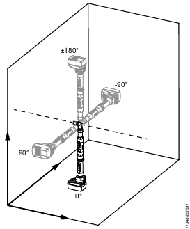
This setting enables the tool to use tool orientation (roll- and pitch axis) as a criteria for when to enable and disable the tool. The orientation setting can be defined manually or by using a teach mode.
The tool can only measure two rotational axis. Due to the limitations in sensor technology the rotation around the Earth's gravity vector (yaw axis) cannot be detected.
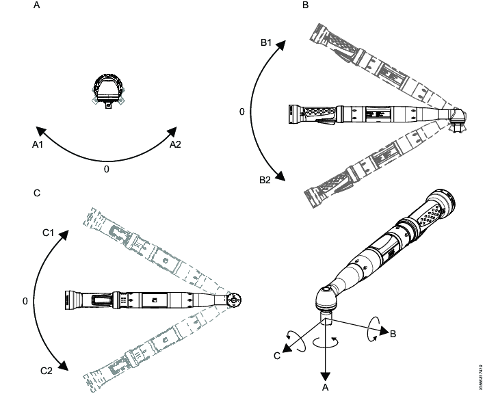
A | Roll | B | Pitch |
C | Yaw |
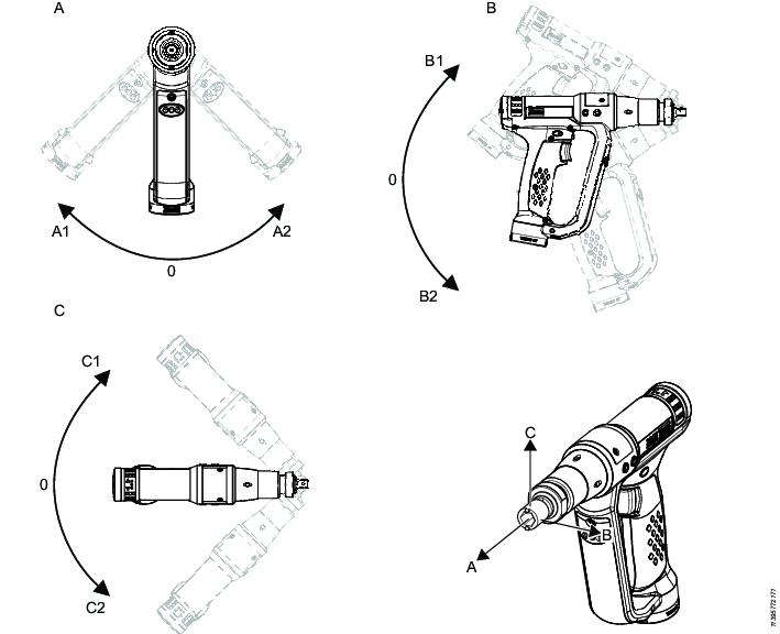
A | Roll | B | Pitch |
C | Yaw |
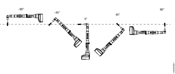
Pitch
The rotational angle between the tool's socket axis and a vertical plane. Values: between -90° and 90°.
The video below shows an example of pitch in Angle tools.
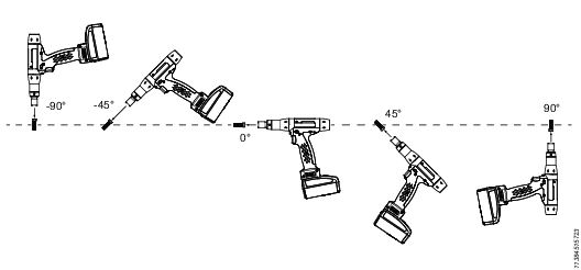
Roll
The rotational angle around the tool's socket center axis. Values: between -180° and 180°.
At pitch ± 90°, roll cannot be measured.
The video below shows an example of roll in Angle tools.
On the Edit Area screen select Orientation.
Select the check box for Use Orientation, more options are now visible.
Choose to either set the orientation manually or using the Teach Orientation function.
Select Teach orientation.
Select a delay time by tapping Time delay. The options are: No (default value), 5 seconds, 10 seconds, or 15 seconds.
Place the tool in the correct orientation and press Start calibration.
To adjust the orientation settings, if needed, follow the same procedure as for setting the orientation manually.
Select Orientation - roll, enter the value and then select OK.
Select Orientation - pitch, enter the value and then select OK.
Select Tolerance - roll, enter the value and then select OK. The tolerance for roll is ±30°.
Select Tolerance - pitch, enter the value and then select OK. The tolerance for pitch is ±15°.
Setting Tool Distance Limits in an Area
The distance functionality is used to control the tool behavior based on the distance between tool and the ILT Base Station. In a tool tethering application, the tool would be disabled when exceeding the defined distance limit. The distance limit can be defined manually or by using a teach mode.
The omnidirectional antenna in the ILT Base Station measures distance in all directions from the ILT Base Station.
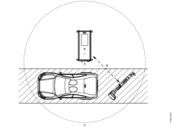
A | ILT Base Station | B | Distance between the ILT Base Station and the ILT Tool Tag |
C | Maximum distance from the ILT Base Station |
On the Edit Area screen, select Distance.
Select the check box for Use Distance, more options are now visible.
Choose to either set the distance manually or using the Teach Distance function.
Select Teach distance.
Select a delay time by tapping Time delay. The options are: No (default value), 5 seconds, 10 seconds, 15 seconds.
Place the tool at the minimum distance limit and press Start calibration.
Place the tool at the maximum distance limit and press Start calibration.
To adjust the minimum and maximum distance, if needed, follow the same procedure as for setting the distance manually.
Select Min distance, enter the minimum distance and then select OK.
Select Max distance, enter the minimum distance and then select OK.
Enter the distance in meters.
Setting the Area Priority
The priority setting defines which tightening program should be selected if more than one area is active simultaneously.
On the Edit Area screen, select Priority.
Enter the priority number and then select OK
A higher number is prioritized over a lower number. 10 has priority over 1.
Deleting an Area
On the Edit Area screen, select Delete and then select OK.
Importing an ILT Base Station Configuration
A configuration from another ILT Base Station can be imported if needed.
Download the configuration to a USB drive.
The configuration file must be placed at root level on the USB drive.
On the ILT Base Station, remove the lid protecting the USB port and connect the USB drive.
From the Home screen, select System, then select USB, and then select Import configuration.
Select the correct configuration.
There can be several configuration files on one USB drive.
Select Yes to confirm the import of the new configuration. The ILT Base Station will restart after the transfer.
After the restart, remove the USB drive and close the lid protecting the USB port.
Exporting the ILT Base Station Configuration
A complete configuration backup for the ILT Base Station is created on the USB drive. This configuration file can be imported to another ILT Base Station or stored for later use.
On the ILT Base Station, remove the lid protecting the USB port and connect the USB drive.
From the Home screen, select System, then select USB, and then select Export configuration.
The current configuration is saved to the USB drive.A confirmation message will appear at the bottom of the screen after a successful export.
Remove the USB drive and close the lid protecting the USB port.
Exporting Logs
Exporting logs will create files for troubleshooting purposes.
On the ILT Base Station, remove the lid protecting the USB port and connect the USB drive.
From the ILT Base Station Home screen, select System, then select USB, and then select Export log to save the log files.
The export can take up to ten minutes.
A confirmation message will appear at the bottom of the screen after a successful export.
Remove the USB drive and close the lid protecting the USB port.
Operation
In this section, you can find step-by-step information about how to operate the product.
Working with the Tools and Status Screens
The Tools screen
The Tools screen shows an overview of all connected tools. The status of each virtual station is indicated with different colors.
Color | Status |
|---|---|
Green | Tool unlocked |
Blue | Tool locked |
White | Power Focus not connected |
Gray | ILT Tool Tag not connected |
Activating the Tools screen
Select Status to access the Tools screen from the Home screen.
The Status screen
From the Tools screen it is possible to access the Status screen for each virtual station. The Status screen displays which area and tightening program that are active and whether the tool is enabled or disabled. It also shows current measurements for orientation and distance.
An open padlock symbol  shows that an Area is enabled.
A closed padlock symbol  shows that an Area is disabled.
Only one area can be active at the time.
Viewing a specific Area on the Status screen
Select the configuration symbol
 and select an Area from the list to view it in detail.
Activating the Status screen
On the Home screen, select Status, and select a Virtual Station on the Tools screen. The Status screen opens.
The Status screen will also be displayed after the Inactivity Timeout has been reached if one tool is used. If multiple tools are used the Tools screen will be displayed.
Changing font size on the Status screen
On the Status screen, select the symbol with the small and large T
 to switch between font sizes. The small font size is default.