Industrial Location Pointsense
Positioning system
Product Information
General Information
Safety Signal Words
The safety signal words Danger, Warning, Caution, and Notice have the following meanings:
DANGER | DANGER indicates a hazardous situation which, if not avoided, will result in death or serious injury. |
WARNING | WARNING indicates a hazardous situation which, if not avoided, could result in death or serious injury. |
CAUTION | CAUTION, used with the safety alert symbol, indicates a hazardous situation which, if not avoided, could result in minor or moderate injury. |
NOTICE | NOTICE is used to address practices not related to personal injury. |
Warranty
Product warranty will expire 12+1 months after dispatch from Atlas Copco's Distribution Center.
Normal wear and tear on parts is not included within the warranty.
Normal wear and tear is that which requires a part change or other adjustment/overhaul during standard tools maintenance typical for that period (expressed in time, operation hours or otherwise).
The product warranty relies on the correct use, maintenance, and repair of the tool and its component parts.
Damage to parts that occurs as a result of inadequate maintenance or performed by parties other than Atlas Copco or their Certified Service Partners during the warranty period is not covered by the warranty.
To avoid damage or destruction of tool parts, service the tool according to the recommended maintenance schedules and follow the correct instructions.
Warranty repairs are only performed in Atlas Copco workshops or by Certified Service Partners.
Atlas Copco offers extended warranty and state of the art preventive maintenance through its ToolCover contracts. For further information contact your local Service representative.
For electrical motors:
Warranty will only apply when the electric motor has not been opened.
Website
Information concerning our Products, Accessories, Spare Parts and Published Matters can be found on the Atlas Copco website.
Please visit: www.atlascopco.com.
ServAid
ServAid is a portal that is continuously updated and contains Technical Information, such as:
Regulatory and Safety Information
Technical Data
Installation, Operation and Service Instructions
Spare Parts Lists
Accessories
Dimensional Drawings
Please visit: https://servaid.atlascopco.com.
For further Technical Information, please contact your local Atlas Copco representative.
Safety Data Sheets MSDS/SDS
The Safety Data Sheets describe the chemical products sold by Atlas Copco.
Please consult the Atlas Copco website for more information www.atlascopco.com/sds.
Country of Origin
For the Country of Origin, please refer to the information on the product label.
Dimensional Drawings
Dimensional Drawings can be found either in the Dimensional Drawings Archive, or on ServAid.
Please visit: https://webbox.atlascopco.com/webbox/dimdrw or https://servaid.atlascopco.com.
Overview
Technical Product Data
Technical Product Data can be found on either ServAid, or the Atlas Copco website.
Please visit: https://servaid.atlascopco.com or www.atlascopco.com.
Accessories
Recommended Accessories
The socket extension is a recommended accessory to install on the angle gear. The recommended minimum length of the socket extension is 10 cm. The maximum length of the socket extension depends on the workpiece.
Overview LED Behavior
ILP States | LED behavior | Comment |
|---|---|---|
Running | ||
Startup | Blinking white | |
Operational | Steady white | |
Correct bolt | Steady blue | |
Error | Blinking red | |
Power saving mode | Breathing white | |
Teaching | ||
The teaching is recording (The user presses the record button or the tool trigger) | Steady white | |
The ILP sensor is collecting information of the workpiece | Blinking blue | |
Error (e.g. lost connection with the application) | Blinking red | |
A smeared/scratched glass cover is detected | Blinking yellow | |
Installation
Installation Instructions
Installing accessories
Preparation
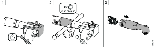
Check the serial number on the cap nut of the tool. There are two alternatives:
a) The serial number starts with generation letter A or B.
b) The serial number starts with generation letter C.

Required tools:
Adjustable spanner
Screwdriver
Put the front part in a clamping jaw of a suitable size and fasten the clamping jaw in a vise.
Loosen the front cap nut using an adjustable spanner. Remove the tool from the vise.
Pull out the angle gear carefully from the tool.
Remove the following parts from the angle gear housing:
The lock ring (keep for later use).
The sealing washer (to be discarded).
The front cap nut (to be discarded).
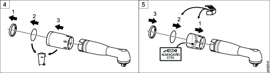
Mount the following parts on the angle gear housing:
New suitable front cap nut. Apply a thin layer of grease on the inside of the cap nut.
New sealing washer.
Lock ring.
Replace the O-ring on the motor housing with an O-ring with the same diameter but thicker. Apply a thin layer of grease on the O-ring and on the lower section of the motor housing.
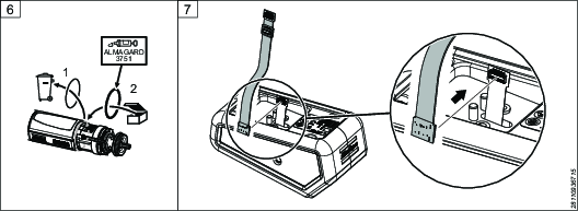
Connect the correct adapter cable to the ILP Primary Flex cable on the ILP module.

For tools with generation letter A/B, use the adapter cable ILP-ILM ITBA-A/B Flex Adapter. For tools with generation letter C, use the adapter cable ILP-ILM ITBA-C Flex Adapter.
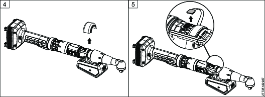
Make sure to connect the correct end of the adapter cable, the one with one connector, to the cable on the ILP module. It should be connected in the correct orientation, as can be seen in step 6 of the instructional diagram below.
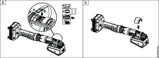
Connect the other end of the adapter cable to the USB port on the tool.
Make sure to connect the correct cable connector (B) to the USB port.
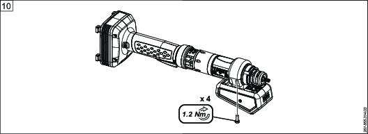
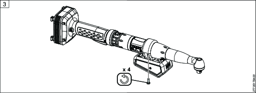
Place the upper ring on the tool.
Tighten the lower ring and the upper ring (the half-rings) with 4 screws using a screwdriver.
Make sure the sealing on the end of the half-rings seals tightly.
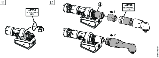
Place an O-ring in the slot at the front of the half-rings. Apply a thin layer of grease on the O-ring.
Pull out the planetary gear from the gear housing. Push down the planetary gear fully on the shaft.
Make sure the gear wheel is placed in correct position.
Put the gear back in position. Apply a thin layer of grease on the sealing washer.
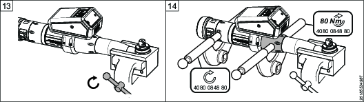
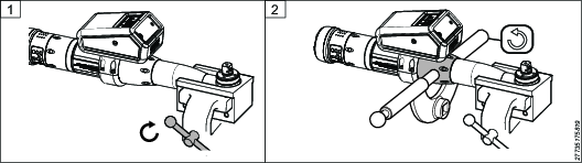
Put the front part in the clamping jaw and fasten the clamping jaw in the vise.
Tighten the front cap nut using adjustable spanners.
Removing accessories
Required tools:
Adjustable spanner
Screwdriver
Put the front part in the clamping jaw and fasten the clamping jaw in the vise.
Loosen the front cap using the adjustable spanner.
Loosen the 4 screws securing the two half-rings using a screwdriver.
Remove the upper ring from the tool.
Disconnect the flex cable from the USB port and remove the ILP module.
Operation
Ergonomic Guidelines
Consider your workstation as you read through this list of general ergonomic guidelines to identify areas for improvement in posture, component placement, or work environment.
Take frequent breaks and change work positions frequently.
Adapt the workstation area to your needs and the work task.
Adjust for a convenient reach range by determining where parts and tools need to be located to avoid static load.
Use workstation equipment such as tables and chairs appropriate for the work task.
Avoid work positions above shoulder level or with static holding during assembly operations.
When working above shoulder level, reduce the load on the static muscles by lowering the weight of the tool, using for example torque arms, hose reels or weight balancers. You can also reduce the load on the static muscles by holding the tool close to the body.
Take frequent breaks.
Avoid extreme arm or wrist postures, particularly during operations requiring a degree of force.
Adjust for a convenient field of vision that requires minimal eye and head movements.
Use appropriate lighting for the work task.
Select the appropriate tool for the work task.
In noisy environments, use ear protection equipment.
Use high-quality inserted tools and consumables to minimize exposure to excessive levels of vibration.
Minimize exposure to reaction forces.
When cutting:
A cut-off wheel can get stuck if the cut-off wheel is bent or not guided properly. Use the correct flange for the cut-off wheel and avoid bending the cut-off wheel during operation.
When drilling:
The drill might stall when the drill bit breaks through. Use support handles if the stall torque is high. The safety standard ISO11148 part 3 recommends using a device to absorb a reaction torque above 10 Nm for pistol grip tools and 4 Nm for straight tools.
When using direct-driven screwdrivers or nutrunners:
Reaction forces depend on the tool settings and joint characteristics. Strength and posture determine the amount of reaction force that an operator can tolerate. Adapt the torque setting to the operator's strength and posture and use a torque arm or reaction bar if the torque is too high.
In dusty environments, use a dust extraction system or wear a mouth protection mask.
Operating Instructions
Operating the ILP
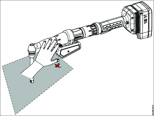
During operation, the workpiece needs to look the same as during teaching. Do not change anything in the field of view after the teaching is completed.
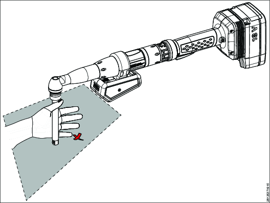
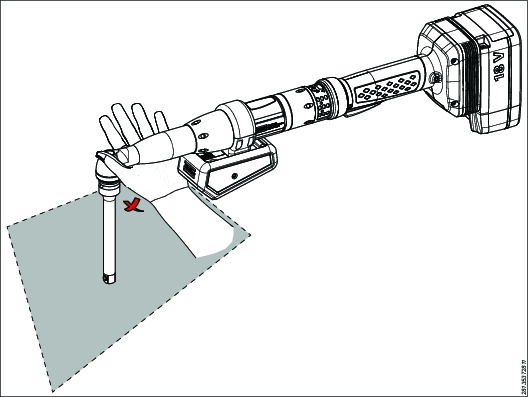
Do not interfere and do not cover the area that will be registered by the sensor while operating the tool:
Do not grab the socket extension.
Do not grab the angle gear of the tool.
Do not cover the lense cover of the ILP module.
Service
Maintenance Instructions
Service Recommendations
Preventive maintenance is recommended at regular intervals. See the detailed information on preventive maintenance. If the product is not working properly, take it out of service and inspect it.
If no detailed information about preventive maintenance is included, follow these general guidelines:
Clean appropriate parts accurately
Replace any defective or worn parts
Cleaning the ILP Module
Clean the lense cover with a soft cloth.
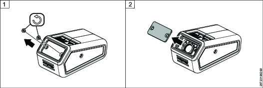
Replacing the Lens Cover
A damaged lens cover should be replaced. This page describes how to replace the lens cover.
Loosen and remove the two screws that attach the lens cover to the housing.
Remove the lens cover.
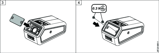
Place the new lens cover on the housing.
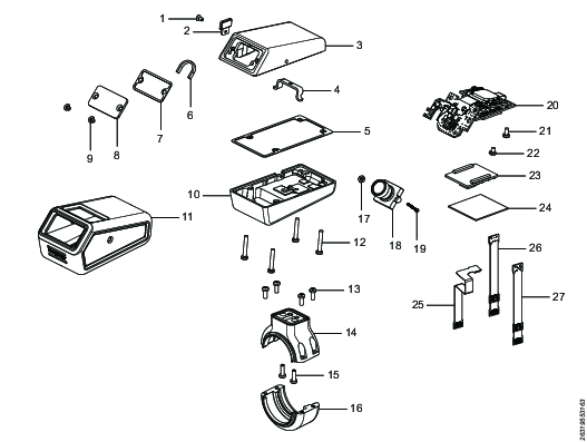
Place the screws in the holes in the lens cover and tighten the screws with a maximum torque of 0.3 Nm.
If screws are tightened with more than 0.3 Nm, the lens cover might break.
To replace the original screws, use TUF-LOK® screws or regular screws on which threadlocker (for example, LOCTITE® 222) has been applied.
Troubleshooting
Troubleshooting for ILP
Problem | Possible cause | Solution |
|---|---|---|
The LED is blinking red. | There is no active connection between the ILP and the ILG. |
|
The is no ILG license. |
| |
The ILG license is inactive. |
| |
The adapter cable is connected incorrectly. |
| |
Something is wrong with the sensor. |
| |
No LED and no connection to the ILP module. | There is no power. |
|
The wrong adapter cable is being used, and is connected to the ILP Primary Flex cable and to the tool. |
|
Recycling
Environmental Regulations
When a product has served its purpose it has to be recycled properly. Dismantle the product and recycle the components in accordance with local legislation.
Batteries shall be taken care of by your national battery recovery organization.
Recycling Information
Pos. | Part | Recycle as |
|---|---|---|
1 | Screw | Metal, Steel |
2 | USB bracket cpl | Metal, Aluminum Rubber |
3 | Housing bottom | Metal, Aluminum |
4 | Bracket | Metal, Aluminum |
5 | Housing seal | Rubber |
6 | Light seal | Rubber Plastics |
7 | Front seal | Rubber |
8 | Lense cover | Plastics |
9 | Screw | Metal, Steel |
10 | Housing top | Metal, Steel Metal, Aluminum |
11 | Protective cover | Rubber |
12 | Screw | Metal, Steel |
13 | Screw | Metal, Steel |
14 | Lower ring S | Metal, Aluminum |
15 | Screw | Metal, Steel |
16 | Upper ring S | Metal, Aluminum |
17 | Knot | Metal, Steel |
18 | Lense housing | Plastics Glass |
19 | Screw | Metal, Steel |
20 | PCB | Electronics |
21 | Screw | Metal, Steel |
22 | Screw | Metal, Steel |
23 | Processor | Electronics |
24 | Heat pad | Rubber |
25 | ILP primary flex | Electronics |
26 | ILP-ILM ITBA-A/B flex adapter | Electronics |
27 | ILP-ILM ITBA-C flex adapter | Electronics |