Tensioning Procedure
Procedure
Make sure that the two halves of the bolted joint are fully and correctly aligned.
Fit the hydraulic nuts to all of the stud bolts.
See section Hydraulic Nut System Configuration for configuration illustrations of hydraulic nut set up.
See section Hydraulic Nut Installation for installation instructions.
Make sure the pump is turned off and the pressure release valve is in the open position.
By using suitable link hoses, connect the hydraulic nuts together and to a suitable pump unit.

If simultaneous tensioning of more than one bolt is to be carried out, fit one male and one female quick connect coupling to each hydraulic nut, and by using link hoses, link each nut together. The end nut on the application should have either an unconnected female coupling (to a link hose) or a blanking plug.
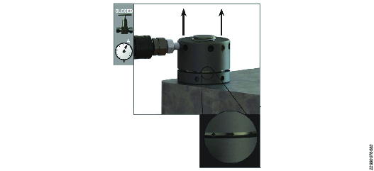
Make sure the tensioning team is aware of the target working pressure.
Operate the pump unit and pressurize the system to 1000 psi (70 bar) and check that the pressure is holding steady. If the pressure drops, investigate the problem by looking for leaks.
For pump operation, see the pump instruction document.
All investigation, maintenance or leak repair work should only be carried out when the tensioning system is at zero pressure.
When the pressure is holding steady, continue to pressurize the system up to the target calculated working pressure.
Never exceed the maximum working pressure.
Never leave high pressure hydraulic tools unattended while pressurized.
Never exceed the maximum piston stroke capability of the tensioning tool.
If the maximum stroke indicator appears on any of the tools before the target operating pressure is reached, immediately stop the pressurization sequence. Slowly open the pump pressure release valve and make sure that the pressure drops to zero. Return the body and restart the tensioning procedure.
When the target working pressure is reached, stop the pump to hold pressure. Monitor the pump pressure gauge to make sure the pressure is holding steady.
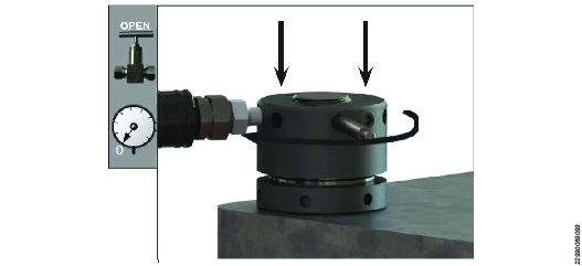
Approach the hydraulic nuts and by using a tommy bar inserted into the load retaining collar, rotate the collar upwards until it is seated tightly up against the underside of the hydraulic nut body. Repeat until all of the load retaining collars are firmly seated.


Slowly open the pressure release valve, the pressure will drop to zero.
Repeat steps 5 to 9.
Open the pump pressure release valve and make sure the pressure falls to zero.
Remove all link hoses from the hydraulic nuts.
Remove the hydraulic coupler(s) and replace the blanking plugs that were removed during the hydraulic nut installation.
Hydraulic couplers of either type should be tightened into the tool from the adaptor piece only. Required tightening torque is 25 Nm.
The tensioning procedure is now complete.


