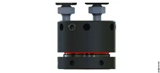
Bottom Collar Hydraulic Nut
Hydraulic Nut
Product Information
General Information
Safety Signal Words
The safety signal words Danger, Warning, Caution, and Notice have the following meanings:
DANGER | DANGER indicates a hazardous situation which, if not avoided, will result in death or serious injury. |
WARNING | WARNING indicates a hazardous situation which, if not avoided, could result in death or serious injury. |
CAUTION | CAUTION, used with the safety alert symbol, indicates a hazardous situation which, if not avoided, could result in minor or moderate injury. |
NOTICE | NOTICE is used to address practices not related to personal injury. |
Warranty
Product warranty will expire 12+1 months after dispatch from Atlas Copco's Distribution Center.
Normal wear and tear on parts is not included within the warranty.
Normal wear and tear is that which requires a part change or other adjustment/overhaul during standard tools maintenance typical for that period (expressed in time, operation hours or otherwise).
The product warranty relies on the correct use, maintenance, and repair of the tool and its component parts.
Damage to parts that occurs as a result of inadequate maintenance or performed by parties other than Atlas Copco or their Certified Service Partners during the warranty period is not covered by the warranty.
To avoid damage or destruction of tool parts, service the tool according to the recommended maintenance schedules and follow the correct instructions.
Warranty repairs are only performed in Atlas Copco workshops or by Certified Service Partners.
Atlas Copco offers extended warranty and state of the art preventive maintenance through its ToolCover contracts. For further information contact your local Service representative.
For electrical motors:
Warranty will only apply when the electric motor has not been opened.
Website
Information concerning our Products, Accessories, Spare Parts and Published Matters can be found on the Atlas Copco website.
Please visit: www.atlascopco.com.
ServAid
ServAid is a portal that is continuously updated and contains Technical Information, such as:
Regulatory and Safety Information
Technical Data
Installation, Operation and Service Instructions
Spare Parts Lists
Accessories
Dimensional Drawings
Please visit: https://servaid.atlascopco.com.
For further Technical Information, please contact your local Atlas Copco representative.
Safety Data Sheets MSDS/SDS
The Safety Data Sheets describe the chemical products sold by Atlas Copco.
Please consult the Atlas Copco website for more information www.atlascopco.com/sds.
Country of Origin
For the Country of Origin, please refer to the information on the product label.
Dimensional Drawings
Dimensional Drawings can be found either in the Dimensional Drawings Archive, or on ServAid.
Please visit: http://webbox.atlascopco.com/webbox/dimdrw or https://servaid.atlascopco.com.
Overview
Technical Product Data
Technical Product Data can be found on either ServAid, or the Atlas Copco website.
Please visit: https://servaid.atlascopco.com or www.atlascopco.com.
Installation
Installation Instructions
Hydraulic Nut Installation
Preparations
Read the section Hydraulic Nut System Configuration to select appropriate hydraulic nut arrangement.
Make sure that the stud bolt threads are clean and free of damage.
Installation
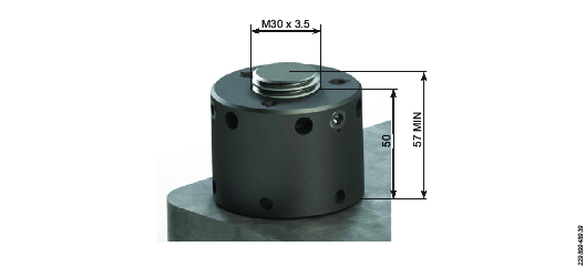
Assemble the hydraulic nut onto the stud bolt. Make sure adequate stud bolt protrusion is available. Refer to the General Arrangement drawing for this information.

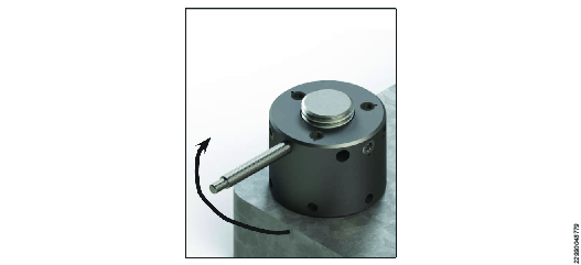
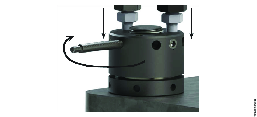
Screw down the hydraulic nut by using a tommy bar until it is seated on the joint face.
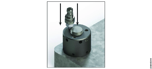
Remove the most accessible blanking plug(s) and replace them with the required configuration of male and female high pressure couplers.

Hydraulic couplers of either type should be tightened into the tool from the adaptor piece only. Required tightening torque is 25 Nm.
Make sure that the pump pressure release valve is fully open and the pump is switched off. Connect the link hoses to the hydraulic nuts.
If simultaneous tensioning of more than one bolt is to be carried out, fit one male and one female quick connect coupling to each hydraulic nut, and by using link hoses, link each nut together. The end nut on the application should have either an unconnected female coupling (to a link hose) or a blanking plug.

Hydraulic Nut System Configuration
The most efficient use of stud bolt tensioning tools is where every stud bolt is tensioned simultaneously; 100% stud bolt to hydraulic nut ratio. Hydraulic nuts can be fitted to either one or both sides of the bolted joint depending on accessibility.
Generally with hydraulic nuts, 100% of the bolts are tensioned simultaneously.
1 | Link hose |
2 | Link hose to the pump |
1 | Link hose |
2 | Link hose to the pump |
3 | It is OK to leave a female coupler unconnected |
Hydraulic Nut Arrangement - 100% Configuration
On some applications it is not be possible to fit hydraulic nuts to every stud bolt from the same side of the bolted joint. In that case it is necessary to stagger the hydraulic nuts over both sides of the bolted joint. In either configuration, it is normal practice to fit the stud bolts in such way so adequate thread protrudes from the side of the joint that the hydraulic nuts will be fitted. See the pictures below.
It is safe to pressurize an unconnected female connection. The end, unconnected port on a chain of tensioners or hydraulic nuts should contain a female coupling or a blanking plug.
Joint side A: Alternate bolts on a joint showing adequate bolt protrusion.

Joint side B: Alternate bolts on a joint showing adequate bolt protrusion.

Operation
Operating instructions
Pre-Procedure Checks
Components
Check that each stud bolt to be tensioned is visually free from obvious thread defects. Make sure that all hydraulic nuts are free to rotate on the stud bolts. Make sure that there is sufficient length of stud bolt protruding from the joint face. Refer to the general arrangement drawing to confirm the correct level of stud bolt protrusion required. Also make sure that full thread engagement is available through the nut on the opposite end of the stud bolt being tensioned.
Check that all calculations pertaining to the tensioning procedure, including pressures, bolt loads, etc are available and have been reviewed by a qualified engineer with bolting experience.
Inspect the hose to make sure that no cracking, peeling or other damage has occurred to the polyamide material of the hose. Damaged hose must be replaced.
Pump
Make sure that personnel has fully read and understood the Product Instructions and Safety Information for the pump.
Make sure that the pump reservoir is filled with an adequate oil volume.
Make sure that the correct and preferred grade of oil is used in the pump.
Personnel
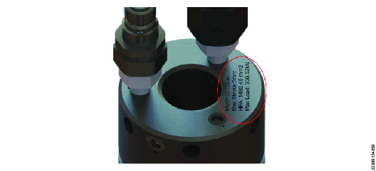
Make sure that all personnel are aware of the maximum working pressure and maximum piston stroke of the hydraulic nuts. These details are hard stamped on the hydraulic nut body.
Always make sure that all personnel in the near vicinity are aware that pressurization of high pressure equipment is about to take place. Cordon off the working area and exclude anyone from the area who is not involved directly with the tensioning procedure.
Make sure that personnel are fully trained in stud bolt tensioning procedures and have fully read this guide and safety notes.
Bolting calculations must be done by qualified engineers who are properly trained or have suitable experience in bolting technology.
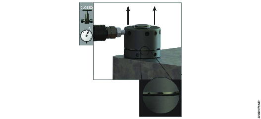
Maximum Stroke Indicator
The maximum approved stroke of the hydraulic nut is indicated by a red line hard stamped into the circumference of the piston.
Continually monitor the piston stroke during pressurization. If the maximum piston stroke indicator becomes visible on any of the hydraulic nuts before the target pressure is reached, immediately stop the pump and release the pressure to zero. Rotate the hydraulic nut body down on the bolt by using a tommy bar until the loadcells are shut down into the zero stroke position. Recommence the tensioning procedure.
Failure to stop the tensioning sequence once the red piston indicator becomes visible may result in failure of the hydraulic nut seal and will eventually cause a release of high pressure fluid which could lead to injury or death.
Escaping high pressure oil can penetrate the skin and is extremely dangerous. Seek urgent medical attention if oil penetrates skin.
Tensioning Procedure
Procedure
Make sure that the two halves of the bolted joint are fully and correctly aligned.
Fit the hydraulic nuts to all of the stud bolts.
See section Hydraulic Nut System Configuration for configuration illustrations of hydraulic nut set up.
See section Hydraulic Nut Installation for installation instructions.
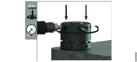
Make sure the pump is turned off and the pressure release valve is in the open position.
By using suitable link hoses, connect the hydraulic nuts together and to a suitable pump unit.
If simultaneous tensioning of more than one bolt is to be carried out, fit one male and one female quick connect coupling to each hydraulic nut, and by using link hoses, link each nut together. The end nut on the application should have either an unconnected female coupling (to a link hose) or a blanking plug.
Make sure the tensioning team is aware of the target working pressure.
Operate the pump unit and pressurize the system to 1000 psi (70 bar) and check that the pressure is holding steady. If the pressure drops, investigate the problem by looking for leaks.
For pump operation, see the pump instruction document.
All investigation, maintenance or leak repair work should only be carried out when the tensioning system is at zero pressure.
When the pressure is holding steady, continue to pressurize the system up to the target calculated working pressure.
Never exceed the maximum working pressure.
Never leave high pressure hydraulic tools unattended while pressurized.
Never exceed the maximum piston stroke capability of the tensioning tool.
If the maximum stroke indicator appears on any of the tools before the target operating pressure is reached, immediately stop the pressurization sequence. Slowly open the pump pressure release valve and make sure that the pressure drops to zero. Return the body and restart the tensioning procedure.
When the target working pressure is reached, stop the pump to hold pressure. Monitor the pump pressure gauge to make sure the pressure is holding steady.
Approach the hydraulic nuts and by using a tommy bar inserted into the load retaining collar, rotate the collar upwards until it is seated tightly up against the underside of the hydraulic nut body. Repeat until all of the load retaining collars are firmly seated.


Slowly open the pressure release valve, the pressure will drop to zero.
Repeat steps 5 to 9.
Open the pump pressure release valve and make sure the pressure falls to zero.
Remove all link hoses from the hydraulic nuts.
Remove the hydraulic coupler(s) and replace the blanking plugs that were removed during the hydraulic nut installation.
Hydraulic couplers of either type should be tightened into the tool from the adaptor piece only. Required tightening torque is 25 Nm.
The tensioning procedure is now complete.
De-Tensioning Procedure
Remove the most accessible blanking plugs from every hydraulic nut to be de-tensioned and replace them with the required male and female couplers.
Hydraulic couplers of either type should be tightened into the tool from the adaptor piece only. Required tightening torque is 25 Nm.
Do not overtighten the connection, it can damage the male sealing cone in the fitting.
Bolting calculations should only be carried out by trained and qualified engineers who have been appropriately trained or have suitable experience in bolting technology.
If simultaneous tensioning of more than one bolt is to be carried out, fit one male and one female quick connect coupling to each hydraulic nut, and by using link hoses, link each nut together. The end nut on the application should have either an unconnected female coupling (to a link hose) or a blanking plug.
Make sure that the pump pressure release valve is fully open and the pump is switched off. Connect the link hoses to the hydraulic nuts. See section Hydraulic Nut System Configuration for different tensioning procedure configurations and illustrations.
Make sure that the pressure rating for the Atlas Copco link hose matches the maximum working pressure of the tool. Refer to the hard stamped details on the hydraulic nut.
The system must be at zero pressure before starting any investigation, maintenance or leak repair work.
During the de-tensioning procedure NEVER exceed the maximum working pressure of the hydraulic nut.
Definition: Break Loose Pressure (BLP) is the pressure at which the user can rotate the load retaining collar on the hydraulic nuts by hand with a tommy bar.
Once the pressure is holding steady, continue to slowly increase the pressure. Apply a light force to a tommy bar inserted into the collar. As soon as the collar rotates, BLP is reached. Once the BLP is found, stop the pump to hold the pressure and make a note of the pressure.

Make sure the pressure is holding steady. By using a tommy bar inserted into the locking collars, unscrew every hydraulic nut locking collar until there is 1mm gap between the collar and joint face. Make sure that the collars do not make contact with the joint face.
If locking collars are difficult to rotate at this BLP, slightly increase the pressure until the locking collars become loose.
Never exceed the maximum working pressure of the hydraulic nuts.
Make sure that the bolt material and joint material can withstand the load you are applying.
Never stand in line with the bolt axis while seating the collar. Unexpected bolt failure can result in serious personal injury or death.

Open the pump pressure release valve and make sure the pressure falls to zero.
Use a tommy bar inserted into the holes in the hydraulic nut body. Rotate them down onto the stud to close the hydraulic nut piston to zero stroke.
Repeat on all hydraulic nuts until all of the pistons are fully closed.
Remove all link hoses from the hydraulic nuts.
Only attempt to uncouple high pressure hydraulics while the system is not holding any pressure.
Remove the hydraulic coupler(s) and replace the blanking plugs removed during installation. Blanking Plugs have a required tightening torque of 25Nm.
Never attempt to remove fittings from a high pressure hydraulic tool when the system is pressurized. Escaping high-pressure oil can penetrate the skin and is extremely dangerous. Seek urgent medical attention if oil penetrates skin.
The tensioning procedure is now complete.
Disassemble the hydraulic nuts from the application. If the hydraulic nut cannot be disassembled from the stud, it means the collar was not backed off enough in step 4 and the de-tensioning sequence must be repeated.

The de-tensioning procedure is complete.
Service
Seal Replacement “Clip - In” Type
Atlas Copco use different seal configurations due to differences in tensioner specifications and tensioner usage environments. This section details the replacement of Clip - In type high pressure seals.

No. | Description |
|---|---|
1 | Seal Clip (outer) |
2 | Seal Clip (inner) |
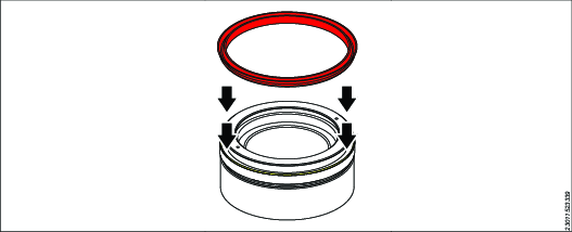
Insert the inner seal into the seal housing. The seal clip fits into the seal clip housing.

With a blunt nose tool, push the seal fully into the seal clip housing. Work around the periphery of the seal until the seal is completely inserted into the clip housing.

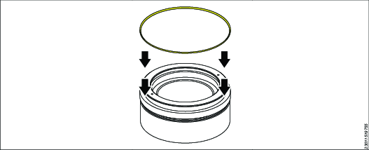
Insert the outer seal into the seal housing. The seal clip fits into the seal clip housing.

With a blunt nose tool, push the seal fully into the seal clip housing. Work around the periphery of the seal until the seal is completely inserted into the clip housing.

Seal Replacement S2/K2 Type
Atlas Copco use different seal configurations due to differences in tensioner specifications and tensioner usage environments. This section details the replacement of S2/K2 type high pressure seals.
Make note of the correct orientation of the triangular backup ring.

Put the outer backup ring into the piston outer seal housing.
Position and stretch the outer seal into the piston outer seal housing.
The seal fits above the backup ring.

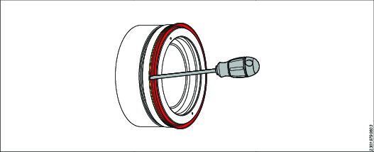
With a rounded smooth screwdriver, push the seal until the seal clips into the seal housing.
Make sure that the seal and backup ring are fully seated around circumference.

Squeeze the inner seal into the inner seal housing.

Push the inner seal in place with a smooth rounded screwdriver.

Put the inner backup ring below the inner seal.

Carefully bend the backup ring to enable it to clip into position. Make sure that the seal and backup ring are fully seated around the circumference.

Maintenance Instructions
Service Recommendations
Preventive maintenance is recommended at regular intervals. See the detailed information on preventive maintenance. If the product is not working properly, take it out of service and inspect it.
If no detailed information about preventive maintenance is included, follow these general guidelines:
Clean appropriate parts accurately
Replace any defective or worn parts
Service Recommendations
General Maintenance
Service must be done by authorized workshops or qualified service technicians.
Examine the tool regularly for signs of corrosion. If signs of corrosion are found, return the tool to the nearest Atlas Copco service center for refurbishment.
Examine the tool coating regularly for signs of cracking or flaking. If any cracking or flaking are found, it is recommended to return the tool to the nearest Atlas Copco service center for advice.
Check lifting eyes and straps on tools for any cracks, tears or other visible damage. Do not use lifting straps or eyebolts that are found to be damaged.
Tools should not be dropped or hit. This can cause damage to the sealing surfaces of the tool which can result in tool failure during usage.
It is recommended to fully refurbish tools every 12 months.
For advice about the operational suitability of the tool, contact Atlas Copco service center.
Tool Storage and Preservation
When the tensioning operation is complete, wipe down all components and carefully remove any water from the tensioner surfaces.
Wipe or spray all surfaces, including those that contain a screwthread, with a non-drying rust prohibitive oil.
Make sure that the dust caps are correctly fitted on all hydraulic fittings. This will prevent foreign objects from getting into the fittings and fouling them.
Store the tool in an upright position.
Store the tool with the ram retracted.
Store the tool in a dry environment.
Troubleshooting
Troubleshooting
Problem | Possible cause | Solution |
|---|---|---|
Hydraulic fluid accumulated on or leaking from hydraulic fittings. System will neither build nor hold pressure. | Fitting or adaptors are loose. | Tighten to torque values stated in assembly and recycling instructions. |
Cannot connect hydraulic fittings. | Hydraulic nuts contain small amount of residual hydraulic pressure. | Slowly loosen fittings on hydraulic nut and/or hose to release residual pressure. |
Fittings are damaged or worn. | Replace fittings. | |
Hydraulic fluid leaking from piston. System will not build pressure. | Hydraulic seals are worn or damaged. | Replace hydraulic seals. |
Hydraulic nut difficult to screw onto bolt. Snagging or locking. | Damage on hydraulic nut or bolt. | Examine internal and external screwthreads for signs of damage or foreign particles. Minor damage can be carefully filed smooth with a needle file. Clean internal and external screwthreads with a wire brush and then wipe with a solvent. |
Dirty screwthreads on hydraulic nut or bolt. |