Product Information
General Information
Safety Signal Words
The safety signal words Danger, Warning, Caution, and Notice have the following meanings:
DANGER | DANGER indicates a hazardous situation which, if not avoided, will result in death or serious injury. |
WARNING | WARNING indicates a hazardous situation which, if not avoided, could result in death or serious injury. |
CAUTION | CAUTION, used with the safety alert symbol, indicates a hazardous situation which, if not avoided, could result in minor or moderate injury. |
NOTICE | NOTICE is used to address practices not related to personal injury. |
Warranty
Product warranty will expire 12 months after the product is first taken into use, but will in any case expire at the latest 13 months after delivery.
Normal wear and tear on parts is not included within the warranty.
Normal wear and tear is that which requires a part change or other adjustment/overhaul during standard tools maintenance typical for that period (expressed in time, operation hours or otherwise).
The product warranty relies on the correct use, maintenance, and repair of the tool and its component parts.
Damage to parts that occurs as a result of inadequate maintenance or performed by parties other than Atlas Copco or their Certified Service Partners during the warranty period is not covered by the warranty.
To avoid damage or destruction of tool parts, service the tool according to the recommended maintenance schedules and follow the correct instructions.
Warranty repairs are only performed in Atlas Copco workshops or by Certified Service Partners.
Atlas Copco offers extended warranty and state of the art preventive maintenance through its ToolCover contracts. For further information contact your local Service representative.
For electrical motors:
Warranty will only apply when the electric motor has not been opened.
ServAid
ServAid is a portal that is continuously updated and contains Technical Information, such as:
Regulatory and Safety Information
Technical Data
Installation, Operation and Service Instructions
Spare Parts Lists
Accessories
Dimensional Drawings
Please visit: https://servaid.atlascopco.com.
For further Technical Information, please contact your local Atlas Copco representative.
Safety Data Sheets MSDS/SDS
The Safety Data Sheets describe the chemical products sold by Atlas Copco.
Please consult the Atlas Copco website for more information www.atlascopco.com/sds.
Product Safety Video for Nutrunners
Learn more about safety features on Atlas Copco nutrunners and what measures the operator has to take for a safe operation. Click the link or scan the QR code below to view the video:
https://www.youtube.com/watch?v=FAh6yttvUpw

Country of Origin
For the Country of Origin, please refer to the information on the product label.
Dimensional Drawings
Dimensional Drawings can be found either in the Dimensional Drawings Archive, or on ServAid.
Please visit: http://webbox.atlascopco.com/webbox/dimdrw or https://servaid.atlascopco.com.
Overview
General Description
The TBP Cordless Pulse Tool is a true game changer. It's a battery powered, low reaction pulse tool with maximum flexibility and high torque. Thanks to the DuraPulse technology the tool uptime is increased and keeps it on the line instead of the tool crib. With TorqueBoost, active cooling and advanced motor steering, the torque build up is fast with reduced hours per production unit and the tool has high productivity. With the lowest vibration levels in the market, the TBP reduces operator fatigue and injuries.
Features
DuraPulse technology with new sealing and air separator
High torque
Excellent ergonomics with low vibrations and reaction force
Cooling system to prevent the tool from over-heating
Easy to set up and assign Virtual Station with Power Focus 6000
Buffer battery
Dual antenna
Rapid Backup Unit (RBU) functionality
Benefits
Increased uptime – up to 5 times
Reduces operator injuries and fatigue
One-handed operation
High performance
Less down-time in production
System Functionality
The POWER FOCUS system sends the tightening program and the batch size to the tool, where it is stored and executed. The tightening result is then sent back to the POWER FOCUS. See schematic figure below.
The tool has the same basic functionality as other tools, but due to the nature of the wireless communication, where the tightening data is stored in the tool, all features in the POWER FOCUS software may not be available for this tool.
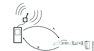
A | Tightening program |
B | Result |
Tool Functionality
The tool is equipped with LED indicators (HMI) that can be configured to output signals related to events, and a buzzer. There are also a number of standard LED warning configurations programmed into the tool.

Number | Description |
|---|---|
1 | LED indicator (HMI) |
2 | Direction switch |
3 | Front LED light |
4 | Function button |
5 | Tool trigger |
6 | Rapid Backup Unit (RBU) and USB port |
7 | Battery or adapter using electrical power cord with power supply unit |
LED Indicator (HMI)

Indicator position | LED indicator | Main indication |
|---|---|---|
1 | Green | Tightening result OK |
2 | Red | Tightening result NOK |
3 | Yellow | Tightening result warning |
4 | White | Tightening direction |
5 | Green | Batch OK complete |
6 | Battery | Battery charge status |
7 | Blue | Radio connection established with POWER FOCUS 6000/ToolsTalk Service 2 |
8 | Blue | Configurable - can be configured in the controller to indicate different events |
9 | Red | Alarm error has occurred in the tool |
For more information, see LED Indicator Flash Patterns.
Memory Capacity
The tool can log up to 2000 results in the tool.
Technical Product Data
Technical Product Data can be found on either ServAid, or the Atlas Copco website.
Please visit: https://servaid.atlascopco.com or www.atlascopco.com.
Service Overview
Service Recommendations
Preventive maintenance is recommended at regular intervals. See the detailed information on preventive maintenance. If the product is not working properly, take it out of service and inspect it.
If no detailed information about preventive maintenance is included, follow these general guidelines:
Clean appropriate parts accurately
Replace any defective or worn parts
Installation
Installation Requirements
Setup Quick Guide
This quick guide uses the residual torque method for parameter settings. There are other methods, although they are not covered here.
During the setup of parameter settings the torque installed may be higher or lower than presented on the POWER FOCUS display screen. The Residual Torque Correlation Factor (RTCF) affects the presented value, make sure to check the residual torque with an ST Wrench or similar if the joint settings are done with parts in ongoing production.
Set the RTCF to 100%.
Always use the intended sockets and extensions (preferably guided sockets and extensions).
Always do the settings on the intended joint.
Reusing the same joint for many tightenings may affect the result.
Set the target torque to the specified torque required.
Tighten the joint with standard POWER FOCUS settings.
Check the torque.
Change the RTCF if the residual torque is a lot lower or higher than seen on the POWER FOCUS. The residual torque should correlate with the POWER FOCUS. If the deviation is small (+/-4 %) continue to the next step.

The RTCF is correlated to the settings that is performed in the next step, do not spend too much time on it in this step.
Increase or decrease power and rundown speed in order to achieve 10-20 pulses during the tightening.
If the joint is very hard or varying from hard to medium hard, adapt the settings for the hardest joint.
Increase power and/or rundown speed if the pulses are too many (>20) as it increases wear and reduces productivity.
Decrease power and/or rundown speed if the pulses are too few as this will result in poor accuracy.
If high productivity is needed, try to get at least 5-10 pulses per tightening.
A rundown speed of 2000 rpm will suffice. If the tightening speed needs to be improved, increase the rundown speed in small increments and evaluate the changes carefully. A high rundown speed reduces the tightening time, but may result in torque overshoot.
If angle monitoring is to be used, the rundown speed may need to be decreased, in order to lower the angle scatter. For more information, contact Atlas Copco Industrial Technique AB Customer Service Center, for the Public Tightening Accuracy Reports for pulse tools.
Tighten the joint with the new settings. Change the settings if needed and redo the tightening.
Do a number of tightenings to check and change the RTCF, see Power Focus 6000 Configuration manual.
Tighten a number of joints with the new RTCF to see if required results are met. If the tool does not perform as intended, redo steps 6 through 9.
Tighten as many joints as needed to check the tool capability on the intended joint.
Installation
For installation guideline, see Power Focus 6000 user guide.
Installation Instructions
Torque Adjustment
For installation of the torque adjustment, see Power Focus 6000 Configuration manual.
The torque adjustment factor is stored in non-volatile memory in the tool. Any changes made to the torque adjustment factor in the POWER FOCUS 6000 will update the stored value in the tool.
Rapid Backup Unit
The Rapid Backup Unit (RBU) has the form factor of an SD card. The RBU contains all the current network configurations and settings. During the installation and configuration some of the parameters are saved on the card. In case of a failure, it is a quick task to remove the card and put it into a new tool and all functionality remains the same.
When the RBU is transferred from one tool to another, the new tool will be updated to the software on the card. Since there is a chance of loss of data during the update procedure, it is good practice to make sure the new tool is already running the same software version as the old tool, to minimize the risk of data loss.
This RBU can not be used for anything but storing the tool configuration data and software. Reformatting the card, as well as manipulating the data on the card through other means than ToolsTalk Service 2, will result in an unusable card.
Note that the saved results associated with the tool will be lost when the RBU is transferred to another tool.
The MAC-address is associated with the RBU, not with the tool itself. When transferring a card to a new tool, the tool's MAC-address will therefore be the RBU's MAC-address.
Tool Conversion
When converting a tool (for example, by changing the front part), you are required to update the tool information in order to reflect the changes made to the tool. For more information see ToolsTalk Service 2 User Edition user guide
When connected to ToolsTalk Service 2 you will not be prompted to change the tool information. To change the tool designation to match the tool conversion, perform the same steps as those for spare part replacements. Use the tool designation of the new part to update the tool.
Since the tool has been converted, the tool information stored on the tool will no longer match the tool designation on the tool sign.
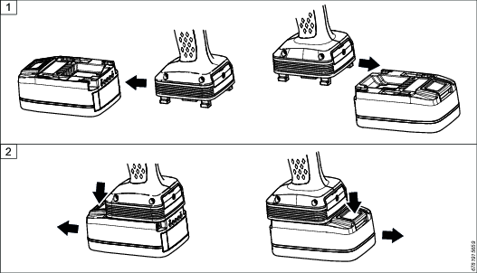
Attaching and Removing the Battery
Attach the battery to the tool and make sure that it is fastened correctly. The battery can be attached pointing forward or backward to get the best accessibility and balance.
To remove the battery, press the button on the battery and push it out.
Initial Configuration
Tool Configuration
To configure the tool, see Power Focus 6000 Configuration manual or ToolsTalk Service 2 User Edition user guide.
Tool Calibration
For information on tool calibration for this tool, see Power Focus 6000 Configuration manual or ToolsTalk Service 2 User Edition user guide.
Operation
Ergonomic Guidelines
Consider your workstation as you read through this list of general ergonomic guidelines to identify areas for improvement in posture, component placement, or work environment.
Take frequent breaks and change work positions frequently.
Adapt the workstation area to your needs and the work task.
Adjust for a convenient reach range by determining where parts and tools need to be located to avoid static load.
Use workstation equipment such as tables and chairs appropriate for the work task.
Avoid work positions above shoulder level or with static holding during assembly operations.
When working above shoulder level, reduce the load on the static muscles by lowering the weight of the tool, using for example torque arms, hose reels or weight balancers. You can also reduce the load on the static muscles by holding the tool close to the body.
Take frequent breaks.
Avoid extreme arm or wrist postures, particularly during operations requiring a degree of force.
Adjust for a convenient field of vision that requires minimal eye and head movements.
Use appropriate lighting for the work task.
Select the appropriate tool for the work task.
In noisy environments, use ear protection equipment.
Use high-quality inserted tools and consumables to minimize exposure to excessive levels of vibration.
Minimize exposure to reaction forces.
When cutting:
A cut-off wheel can get stuck if the cut-off wheel is bent or not guided properly. Use the correct flange for the cut-off wheel and avoid bending the cut-off wheel during operation.
When drilling:
The drill might stall when the drill bit breaks through. Use support handles if the stall torque is high. The safety standard ISO11148 part 3 recommends using a device to absorb a reaction torque above 10 Nm for pistol grip tools and 4 Nm for straight tools.
When using direct-driven screwdrivers or nutrunners:
Reaction forces depend on the tool settings and joint characteristics. Strength and posture determine the amount of reaction force that an operator can tolerate. Adapt the torque setting to the operator's strength and posture and use a torque arm or reaction bar if the torque is too high.
In dusty environments, use a dust extraction system or wear a mouth protection mask.
Configuration Instructions
Tightening Programs
Assigning tightening programs and altering tightening program parameters is done through the controller the tool is paired with.
For more information, see Power Focus 6000 Configuration manual.
Operating Instructions
LED Indicator Flash Patterns
Apart from the LED flash patterns determined by the controller, there are a number of standard flash patterns for the tool LED indicators.
The table below provides an overview of the standard flash patterns.
LED indicator | Light behavior | Status |
|---|---|---|
All indicators | All flashing | Tool has started. |
Battery level | All flashing white: high frequency flashes | Tool is running on the backup battery. |
Battery level | One flashing red | Battery is empty. |
Alarm | Flashing: one flash per second | Invalid configuration of tool WLAN settings in ToolsTalk Service 2. |
Alarm | Flashing: high frequency flashes | Battery software outdated. It is not allowed to operate the tool with batteries running outdated software. |
Radio connection | Blue | Radio connection established / ToolsTalk Service 2 connection established. |
Radio connection | Flashing | Start request not received in time by the tool, due to bad connection. |
Tightening direction | Both directions flashing: high frequency flashing, 3/s. | Software update is ongoing (takes up to 7 minutes). |
Tightening direction | Both directions flashing: high frequency flashes followed by steady light. | Indicates one of the following:
|
Tightening direction | Both direction flashing: low frequency, 1/s. | Tool is connected via USB cable and is waiting for ToolsTalk Service 2 to connect. |
Optimizing the Performance of your Pulse Tool
Recommended Number of Pulses
A Pulse tool well suited for your application should reach the target torque (with shut off) within 5-20 pulses. The number of pulses it takes for the tool to reach target torque can be measured with an analyzer. The tightening time can also be used a guide to know if the tool is appropriate for your application:
≤ 1 second for tools up to 30 Nm
≈ 1 second for tools up to 80 Nm
≈ 2 seconds for tools up to 150 Nm
≈ 5 seconds for tools up to 450 Nm
≤ 10 seconds for tools up to 850 Nm
If the target torque is achieved with less than 5 pulses (= short tightening time), the torque scatter will increase and it can be difficult to adjust to the right level, especially on hard joints.
If the target torque is achieved with more than 20 pulses (= too long tightening time) the wear will increase and more frequent oil filling and service will be required. Too long tightening time, in combination with high production rate, may also result in excessive heating of the oil. In that case the power will decrease with longer tightening time and sometimes no shut off.
If the target torque is achieved with less than 5 pulses this can be fixed by:
Lowering the power setting during tightening.
Reducing the rundown speed.
Changes of power settings and/or rundown speed may affect the torque accuracy.
If the target torque is achieved with more than 20 pulses this can be fixed by:
Increasing the power setting.
Increasing rundown speed.
Changes of power settings and/or rundown speed may affect the torque accuracy.
Tightening
As tightening torque increase the reaction force build up equally. Make sure that the tool is in correct working order and that the controller is correctly programmed. By doing this you avoid unexpected behavior from the tool, which may result in operator injury.
Rotation Direction for the Tightening
Check that the tool is in the correct running direction by turning the reverse button or reverse ring :
Pistol Grip Models (with side buttons)
Press in the reverse switch on the right hand side of the tool, to set the direction clockwise (CW).
Press in the reverse switch on the left hand side of the tool, to set the direction counter clockwise (CCW).
Pistol Grip Models (without side buttons)
Double press the function button on the top of the start trigger to shift the direction between clockwise (CW) and counter clockwise (CCW).
Angle Models
Turn the reverse ring to the right, to set the direction clockwise (CW).
Turn the reverse ring to the left, to set the direction counter clockwise (CCW).
Soft Start
The soft start function facilitates the screwhead and thread to reach the snug level. The duration of the soft start is adjustable.
For further information about tightening, see Power Focus 6000 Configuration manual.
Buzzer
This tool is equipped with a buzzer, which can be configured to signal specific events or warnings.
For more information on the buzzer functionality and configuration, see Power Focus 6000 Configuration Manual.
Service
General Service Information
If the tool is not working properly, take it out of operation for inspection. Preventive maintenance is recommended at regular intervals. See detailed information on Preventive Maintenance.
Make sure to use the service tools, service kits and spare parts recommended by Atlas Copco.
Make sure to follow the Service instructions provided by Atlas Copco.
Make sure to work in a clean environment and that all parts are cleaned before re-assembling. Foreign particles, even small fibers from paper tissue, may affect the service life of the Pulse unit.
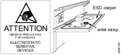
Preventing ESD Problems
The components inside the product and controller are sensitive to electrostatic discharge. To avoid future malfunction, make sure that service and maintenance is carried out in an ESD approved work environment. The figure below shows an example of an appropriate service work station.
Maintenance Instructions
Service Recommendations
Preventive maintenance is recommended at regular intervals. See the detailed information on preventive maintenance. If the product is not working properly, take it out of service and inspect it.
If no detailed information about preventive maintenance is included, follow these general guidelines:
Clean appropriate parts accurately
Replace any defective or worn parts
Maintenance
Daily Inspection
Make sure that the tool is in good condition, no visual damage.
Make sure that sockets and extensions have no visual damage.
Listen to make sure that there is no unexpected noise when running the tool.
Preventive Maintenance
There are several criteria that affect the need for service on this tool:
Type of joint
Torque level
Tightening duration
Production rate
The service intervals and service solutions are based on experience and internal testing.
Preventive Maintenance Level 1
Maintenance level 1
Carry out maintenance after 6.000.000 pulses, when POWER FOCUS 6000 is indicating “Pulse unit oil level low” or once a year, whichever comes first.
For maximum tool performance follow below instructions and use recommended service tools and service kits from Atlas Copco. Always use tightening torque and lubrications as recommended by Atlas Copco.
Tool Handle
Make a visual inspection for any damage.
Inspect the yoke and suspension points.
Inspect the ball bearing in the Pulse unit casing and the surface of the Anvil.
Electric Motor
Listen to any unexpected noise.
Pulse Unit
Change the oil accordingly, see Oil Filling and Changing Instruction for Pulse Unit.
Make sure that the pulsing frequency is within limits, see Tool Condition Test.
Preventive Maintenance Level 2
Maintenance level 2
Carry out maintenance after 12.000.000 pulses, when POWER FOCUS 6000 is indicating “Pulse unit oil level low” or once a year, whichever comes first.
For maximum tool performance follow below instructions and use recommended service tools and service kits from Atlas Copco. Always use tightening torque and lubrications as recommended by Atlas Copco.
Same as level 1 including additional Pulse unit maintenance below:
Pulse unit: Always use lint-free cloth when servicing the pulse unit
Drain all the oil completely from the Pulse unit.
Disassemble the Pulse unit (see spare parts list).
Clean and inspect all parts and surfaces thoroughly for any wear or damage.
Clean the magnets from any metal particles.
Replace both the rollers and pistons at the service interval, if any of them are worn.
Change all O-rings.
Replace the Anvil sealing. Make sure that the cylinder front piece is clean and dry on the inside with no lubrication before assembling the new sealing.
Make sure that the Anvil surface is smooth, clean and lubricated with pulse oil to prevent damages to the anvil sealing during assembly.
It is important that the cam shaft and the separator washer pin is lined up with the groove in the cylinder front piece. If not, the cylinder end piece will not be correctly fastened and the Pulse unit will not function correctly.
Fill the Pulse unit to the right oil level, see Oil Filling and Changing Instruction for Pulse Unit.
Oil Level in the Pulse Unit
The right oil level in the Pulse unit is important for the tool to work correctly.
The need to add oil to the pulse unit will vary depending mainly on the number of tightenings, torque level and number of pulses (tightening time).
Operating the tool on a low oil level will result in faster wear of the parts in the Pulse unit. It will also effect the tool performance.
Detect Low Oil Level in the Pulse Unit
Longer tightening time
Low oil warning
Very high pulse frequency, especially when the tool has not been used for a while.
Low torque
To measure the pulse frequency, see Tool Condition Test.
Overhaul
Have your power tool serviced by a qualified repair person using only identical replacement parts. This will ensure that the safety of the power tool is maintained.
Service must only be carried out by qualified personnel who have access to the Service instruction and/or have been trained for service on this tool.
The electric motor is a sealed unit and may under no circumstances be opened by anyone else than Atlas Copco Industrial Technique AB.
If it is judged that the electric motor is defect or in need of service, the complete motor unit should be returned to Atlas Copco Industrial Technique AB for exchange.
Motors which have been opened by anyone else than Atlas Copco Industrial Technique AB will not be serviced.
Overhaul and preventive maintenance is recommended at regular intervals once per year, after maximum 6.000.000 pulses, depending on which occurs first. More frequent overhaul may be needed if the machine is used in heavy-duty operations. If the machine is not working properly, it should immediately be taken away for inspection.
When dismantling the tool always use the specially designed service tool(s) recommended in the Spare Parts section on ServAid - https://servaid.atlascopco.com.
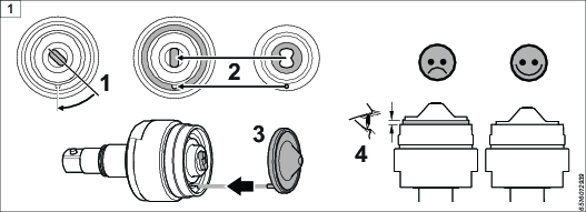
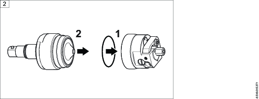
Assembling the Pulse Unit
Make sure to assemble all parts of the Pulse unit in the right order.
It is important that the camshaft and the separator washer pin is lined up with the groove in the cylinder front piece. If not, the cylinder end piece will not be correctly fastened, and the Pulse unit will not function properly.
Lubrication Instructions
Lubricating Guide
Brand | General purpose |
|---|---|
Almagard | LE3752 |
Oil Filling and Changing Instruction for Pulse Unit
Required equipment for oil filling and oil changing:
Atlas Copco Pulse unit oil.
Atlas Copco Pulse unit Oil Filling Kit.
For ordering number for Spare Parts, see https://servaid.atlascopco.com.
Oil Filling Equipment Kit
2 x Adapter M3
2 x Adapter M4
4 x Hose length 540 mm
2 x Hose length 50 mm
1 x Hose length 120 mm
1 x Syringe 50 ml
1 x Syringe 1 ml
4 x Plug
5 x Connection
2 x Connection
2 x Can
2 x Cover
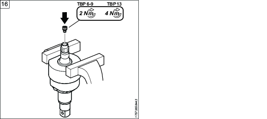
Place the Pulse unit in a vise at an angle so that the outlet whole is at the highest point.
Remove the screw covering the inlet opening. Make sure that the o-ring is on the screw and not left in the Pulse unit. Attach the filling hose by hand, with the hose connector end to the Pulse unit.
Fill the large syringe with oil to maximum capacity from the oil can.
Always use new Atlas Copco Pulse unit oil.
Remove the stop plug from the filling hose and then attach the syringe to the hose.
Remove the screw covering the outlet opening of the Pulse unit. Make sure that the o-ring is on the screw and not left in the Pulse unit. Attach the return hose to the Pulse unit.
Remove the stop plug from the return hose and then attach it to the oil can.
Start filling oil into the Pulse unit from the large syringe. When filling oil into the Pulse unit, there will be air bubbles exiting.
Rotate the anvil back and forth while filling the oil until no more bubbles are coming out of the Pulse unit.
Spin the complete Pulse unit around while filling the oil, to make sure that there are no air bubbles left inside of the Pulse unit.
Remove the return hose from the oil can and attach the stop plug to the return hose end.
Remove the return hose from the outlet opening of the Pulse unit. Put the screw covering the outlet opening back in position.
Now position the Pulse unit in the vise with the inlet opening facing upwards.
Remove the syringe from the filling hose and attach the stop plug to the filling hose.
Remove the oil filling hose from the Pulse unit.
Use the small syringe to extract the right amount of oil, see table Oil Filling.
Put the screw covering the inlet opening back in position.
Model | Oil reduction (X) from 100% full Pulse unit |
|---|---|
ETP TBP/TBP-S 6 | 0.7 ± 0.05 ml |
ETP TBP/TBP-S 8 | 0.7 ± 0.05 ml |
ETP TBP/TBP-S 9 | 1.1 ± 0.05 ml |
ETP TBP/TBP-S 13 | 1.8 ± 0.05 ml |


Re-assembling the Pulse unit
When re-assembling the Pulse unit, it is important to tighten it accordingly.

Model | Tightening torque Nm (A) | Tool (A) |
|---|---|---|
ETP TBP/TBP-S 6 | 40 | 4080 1476 00 |
ETP TBP/TBP-S 8 | 50 | 4080 0891 00 |
ETP TBP/TBP-S 9 | 50 | 4080 1474 00 |
ETP TBP/TBP-S 13 | 50 | 4080 1474 00 |
Repair Instructions
Spare Parts Replacement
When replacing certain electric parts of the tool, the tool designation and parameters are erased from ToolsTalk Service 2 and need to be set again. For more information, see ToolsTalk Service 2 User Edition user guide.
Test After Service
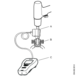
Tool Condition Test

A | Static Torque Transducer SRTT |
B | STa6000 |
Test the maximum torque and pulse frequency
Set the filter frequency in STa6000 to 850 Hz.
Test the max torque and pulse frequency using a SRTT static torque transducer. Tightening time approximately 1 second.
Test Conditions
Temperature pulse unit: approximately 20° C.
In POWER FOCUS 6000, change Tool → Adjustment → Torque Adjustment Factor to 50%, prevents the tool from shutting off. Measure torque and pulse frequency rate clockwise in the SRTT for about 1 second. Check that the values meet the specified limits in table below.
A tool in good condition should achieve the following values:
Model | Pulse frequency | Max Torque CW static (minimum) (Nm) |
|---|---|---|
ETP TBP/TBP-S 6 | 14-20 Hz | > 42 Nm |
ETP TBP/TBP-S 6 (42) | 10-20 Hz | >37 Nm |
ETP TBP/TBP-S 8 | 14-20 Hz | > 64 Nm |
ETP TBP/TBP-S 9 | 10-20 Hz | > 97 Nm |
ETP TBP/TBP-S 13 | 8-15 Hz | > 181 Nm |
Torque Check on Actual Joint
Use the same equipment and settings. For example extensions, sockets and tightening program on the test joint, as will be used on the actual joint.
When performing a torque check on the actual joint we recommend using an STWrench with residual measurement* setting.
* Torque required to cause the threads of the fastener (including its head) on which torque is applied, to move relative to the mating thread.
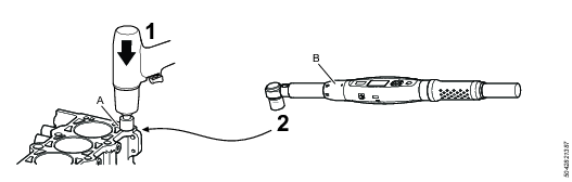
A | The actual joint |
B | Torque wrench |
Perform a tightening.
Measure the result with the Torque wrench.
If the residual torque is not according to the target torque, adjust tightening parameters.
Verification of Tool Accuracy
This test procedure is made in order to verify the tool accuracy. The test is made at three different torque levels with ten (10) tightenings performed at each torque level adding up to 30 tightenings in total. The result is compared with the reference transducer and if the deviation is within limits, the tool passes the test.
Test Conditions and Set Up
The following test conditions need to be fulfilled:
● Use an IRTT as reference transducer.
● Use a test joint with a real screw that gives increased clamp force when tightened, i.e. do not use a brake or similar. The joint should be soft (~100o, the total number of pulses should be >20 during the tightening).
● Do not use any extensions, only the IRTT and socket.
● The STa6000 filter frequency need to be set to 850Hz.
● Tool torque adjustment factor need to be set to 100%.
● The tool needs to be tested at 3 different torque levels, with 10 cycles per level, see table Tool Settings Per Tightening Sequence.
POWER FOCUS 6000 Settings
Stage | Parameter | Setting |
|---|---|---|
1. Start stage | Soft start | OFF |
Re hit detection | OFF | |
2. Rundown stage | Rundown speed | See table1 |
Rundown time limits | OFF | |
Rundown pulse limits | OFF | |
Rundown complete | 5 Nm | |
3. Tightening stage | Target torque | See table1 |
Pulse energy | See table1 | |
Residual torque correlation factor | 1 | |
Premature torque loss detection time | 200 ms | |
| Torque limits | Auto |
Angle limits | OFF | |
Time limits | OFF | |
Pulse limits | OFF |
1 Table: Tool Settings per Tightening Sequence
Tool Settings per Tightening Sequence
Tool model | Sequence | Number of tighetnings | Rundown (rpm) | Pulse energy (%) | Target torque (Nm) |
|---|---|---|---|---|---|
ETP TBP/TBP-S 6 | 1 | 10 | 1500 | 50 | 12 |
2 | 10 | 2000 | 80 | 22 | |
3 | 10 | 3000 | 100 | 32 | |
ETP TBP/TBP-S 8 | 1 | 10 | 1500 | 40 | 20 |
2 | 10 | 2000 | 75 | 37 | |
3 | 10 | 3000 | 100 | 55 | |
ETP TBP/TBP-S 9 | 1 | 10 | 1500 | 50 | 35 |
2 | 10 | 2000 | 85 | 55 | |
3 | 10 | 3000 | 100 | 70 | |
ETP TBP/TBP-S 13 | 1 | 10 | 1600 | 60 | 50 |
2 | 10 | 1900 | 80 | 100 | |
3 | 10 | 2200 | 100 | 150 |
Calculations
Use the results from the tightening, TBP and STa6000 values, to perform the following calculations and evaluations:
1. Calculate mean values
● Calculate the mean torque value (TBP mean) of all results displayed on the POWER FOCUS 6000
● Calculate the mean torque value (STa6000 mean) of all results registered by the STa6000.
2. Calculate the deviation in torque measurement between the TBP tool and STa6000:
Torque measurement factor deviation = 100x [TBPmean-STa6000 mean]÷STa6000 mean
Result for pass is ± 2.0%
3. Normalize the result from the TBP to achieve the same mean value as for the STa6000:
TBP normalized (1…30) = TBP value (1…30) x STa6000 mean÷TBP mean
4. Calculate the deviation between the STa6000 and the POWER FOCUS 6000 for each tightening:
Deviation (1...30) = TBP normalized (1...30) - STa6000 value (1...30)
5. Calculate the standard deviation (Sigma) for the 30 deviations calculated: 
6. Check of torque measurement accuracy in relation to the tool maximum torque (ToolMax), specified per tool model, e.g. 55 Nm for TBP8.
Torque measurement accuracy = 100 x 3 x StdDev)÷ToolMax
Result for pass is: maximum 4.0%
Updating the Tool Software
For information on updating the tool software, see ToolsTalk Service 2 User Edition user guide > Copying Firmware.
To prevent damage to the tool:
Make sure the battery is fully charged when performing a software update.
Do not remove the battery from the tool while the software update is in progress.
Do not remove the memory card from the tool while the software update is in progress.
Troubleshooting
Troubleshooting Guide
Problem | Reason | Action |
|---|---|---|
Tool does not shut off or tightening time is too long. | Target torque close to maximum torque of the tool. | Chose a bigger tool with more power. |
Worn extension or socket/bits. | Check the extension and socket/bits. | |
Incorrect oil level in the Pulse unit. | Adjust the oil level or refill the oil. | |
The joint is too soft for the tool. | Choose a bigger tool with more power or increase pulse energy. | |
Worn parts in the Pulse unit. | Inspect and replace any worn parts. | |
The yield point of the joint is reached. | Check the joint specification. | |
Inconsistent shut off or insufficient accuracy. | The target torque is not within the tool specification. | Change to a different tool size. |
Extension is too long. | Change to shorter extension. | |
Worn extension or socket/bits. | Replace the extension and socket/bits. | |
Incorrect oil level in the Pulse unit. | Adjust the oil level or refill the oil. | |
The joint is too stiff. | Choose a smaller tool or decrease pulse energy. | |
If the tool becomes very hot. | Very high prevailing torque. | Change to a different tool size. |
Very soft joints. | Change to a different tool size. | |
High cycle rate. | Change to a different tool size. |
Events and Error Codes
For a full list of tool event and error codes, see Power Focus 6000 Configuration Manual.
Recycling
Environmental Regulations
When a product has served its purpose it has to be recycled properly. Dismantle the product and recycle the components in accordance with local legislation.
Batteries shall be taken care of by your national battery recovery organization.
Recycling Instruction
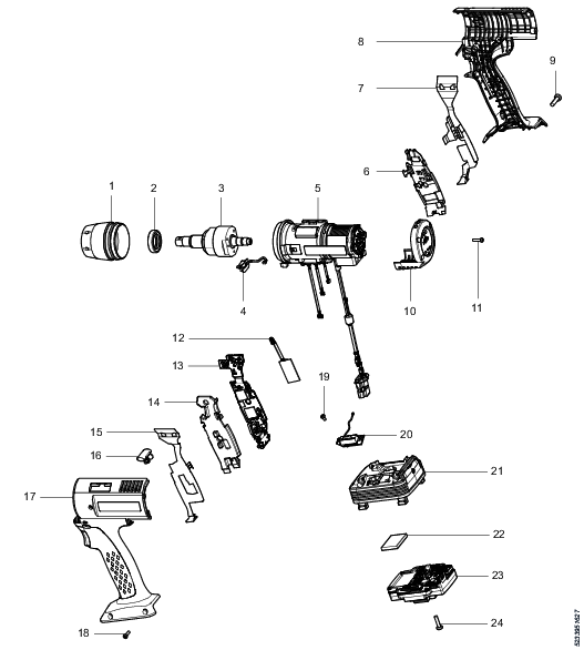
Pos. | Part | Remarks | Recycle as |
|---|---|---|---|
1 | Front cover | Metal, aluminum | |
2 | Bearing | Metal, steel | |
3 | Pulse unit | Metal, steel | |
4 | Front light | Electronics | |
5 | Motor housing, complete | Electronics | |
6 | Main board support rubber | Rubber, PUR | |
7 | GND strip RH | Metal, brass | |
8 | Handle, right | Plastic, other, PA | |
9 | Screws | 8 pcs | Metal, steel |
10 | Back end cover | Plastic, other, PA | |
11 | Screws | 4 pcs | Metal, steel |
12 | Radio module | Electronics | |
13 | Main board module | Plastic, other, PA | |
14 | Main board support rubber | Rubber, PUR | |
15 | GND strip LH | Metal, brass | |
16 | Reverse button | Metal, neodymium | |
17 | Handle, left | Plastic, other, PA | |
18 | Screw | Metal, steel | |
19 | Screw | 4 pcs, to the antennas | Metal, steel |
20 | Antennas | Electronics | |
21 | Battery holder | Metal, aluminum | |
22 | Backup battery | Battery, Li-ion | |
23 | Power module | Electronics | |
24 | Screws | 4 pcs to the power module | Metal, steel |
If TBP tool uses a power supply unit and electrical power cable, see Product Instructions for Power Supply Unit 950W - Recycling Instruction, for more information.