Product Information
General Information
Safety Signal Words
The safety signal words Danger, Warning, Caution, and Notice have the following meanings:
DANGER | DANGER indicates a hazardous situation which, if not avoided, will result in death or serious injury. |
WARNING | WARNING indicates a hazardous situation which, if not avoided, could result in death or serious injury. |
CAUTION | CAUTION, used with the safety alert symbol, indicates a hazardous situation which, if not avoided, could result in minor or moderate injury. |
NOTICE | NOTICE is used to address practices not related to personal injury. |
Warranty
Product warranty will expire 12+1 months after dispatch from Atlas Copco's Distribution Center.
Normal wear and tear on parts is not included within the warranty.
Normal wear and tear is that which requires a part change or other adjustment/overhaul during standard tools maintenance typical for that period (expressed in time, operation hours or otherwise).
The product warranty relies on the correct use, maintenance, and repair of the tool and its component parts.
Damage to parts that occurs as a result of inadequate maintenance or performed by parties other than Atlas Copco or their Certified Service Partners during the warranty period is not covered by the warranty.
To avoid damage or destruction of tool parts, service the tool according to the recommended maintenance schedules and follow the correct instructions.
Warranty repairs are only performed in Atlas Copco workshops or by Certified Service Partners.
Atlas Copco offers extended warranty and state of the art preventive maintenance through its ToolCover contracts. For further information contact your local Service representative.
For electrical motors:
Warranty will only apply when the electric motor has not been opened.
Website
Information concerning our Products, Accessories, Spare Parts and Published Matters can be found on the Atlas Copco website.
Please visit: www.atlascopco.com.
ServAid
ServAid is a portal that is continuously updated and contains Technical Information, such as:
Regulatory and Safety Information
Technical Data
Installation, Operation and Service Instructions
Spare Parts Lists
Accessories
Dimensional Drawings
Please visit: https://servaid.atlascopco.com.
For further Technical Information, please contact your local Atlas Copco representative.
Safety Data Sheets MSDS/SDS
The Safety Data Sheets describe the chemical products sold by Atlas Copco.
Please consult the Atlas Copco website for more information www.atlascopco.com/sds.
Product Safety Video for Nutrunners
Learn more about safety features on Atlas Copco nutrunners and what measures the operator has to take for a safe operation. Click the link or scan the QR code below to view the video:
https://www.youtube.com/watch?v=FAh6yttvUpw

Country of Origin
For the Country of Origin, please refer to the information on the product label.
Dimensional Drawings
Dimensional Drawings can be found either in the Dimensional Drawings Archive, or on ServAid.
Please visit: http://webbox.atlascopco.com/webbox/dimdrw or https://servaid.atlascopco.com.
Overview
Applications
This easy-to-handle Rapid Torque Pneumatic (RTP) nutrunner, together with an FRL unit and reaction bar, is used for tightening and loosening bolts.
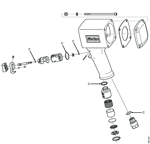
Main components and functions
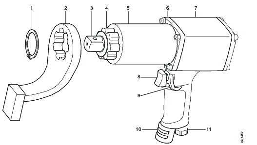
Pos | Component | Function |
|---|---|---|
1 | Circlip | Holds the reaction bar in place. |
2 | Reaction bar | Enables the tool to withstand the reaction force. |
3 | Square drive | Locks the socket to the tool and transfers torque. |
4 | Reaction bar spline | Transfers the reaction force from the gears into the reaction bar. |
5 | Gear unit | Gears up the torque from the air motor, transfers torque into the square drive and reaction force into the reaction bar spline. |
6 | Swivel unit | Enables the gear unit and reaction bar to rotate freely from the motor housing unit. |
7 | Motor housing unit | Holds the air motor, swivel adapter and handle. |
8 | Push button | Starts the tool in the direction defined by the reversing lever. |
9 | Reversing lever | Defines the rotation direction, CW, CCW. |
10 | Silencer | Lowers the output sound pressure and guides the air away from the operator. |
11 | Inlet adapter | Connects the tool into the air preparation unit - pressurized air. |
Technical Product Data
Technical Product Data can be found on either ServAid, or the Atlas Copco website.
Please visit: https://servaid.atlascopco.com or www.atlascopco.com.
Service Overview
Service Recommendations
Preventive maintenance is recommended at regular intervals. See the detailed information on preventive maintenance. If the product is not working properly, take it out of service and inspect it.
If no detailed information about preventive maintenance is included, follow these general guidelines:
Clean appropriate parts accurately
Replace any defective or worn parts
Preventive maintenance
Daily maintenance: Visual inspection of all visible parts on the tool, including the reaction bar. Worn parts should be inspected thoroughly. If defects are found, the tool has to be repaired by qualified personel.
On a regular basis and when needed: make sure that the filter in the FRL unit is clean, the oil level is above minimum and no water is in the compressed air.
Environmental circumstances
Daily maintenance if needed.
All environments are different; take the time to learn what your environment is like, and build your maintenance on this knowledge.
When the tool is used in an environment with a large amount of water in the surroundings, special care has to be taken to keep the internal and external parts free from water during storage. If the tool is stored for a long time, it is recommended that the tool is disassembled and that internal/external parts are free from water. All parts should be re-greased and re-oiled, according to the instructions before storage.
When the tool is used in an environment with a lot of particles in the pressurized air system, make sure that the filter in the FRL unit is clean, as well as the filter in the silencer of the tool. Too many particles will change the performance of the tool.
The tool is intended for lubricated air, supplied by the FRL unit. Make sure that the oil level is above minimum levels on a regular basis.
Installation
Installation Requirements
Air Quality
For optimum performance and maximum product life we recommend the use of compressed air with a maximum dew point of +10°C (50°F). We also recommend to install an Atlas Copco refrigeration type air dryer.
Use a separate air filter which removes solid particles larger than 30 microns and more than 90% of liquid water. Install the filter as close as possible to the product and prior to any other air preparation units to avoid pressure drop.
For impulse/impact tools make sure to use lubricators adjusted for these tools. Regular lubricators will add too much oil and therefore decrease the tool performance due to too much oil in the motor.
Make sure that the hose and couplings are clean and free from dust before connecting to the tool.
Both lubricated and lubrication free products will benefit from a small quantity of oil supplied from a lubricator.
Air Lubrication Guide
Brand | Air lubrication |
|---|---|
Atlas Copco | Optimizer (1 liter) 9090 0000 04 |
Q8 | Chopin 46 |
Shell | Shell Air Tool Oil S2 A 320 |
Compressed Air Connection
For correct air pressure and hose size, see the Technical Product Data on - https://servaid.atlascopco.com or www.atlascopco.com.
Make sure that the hose and couplings are clean and free from dust before connecting to the tool.
Installation Instructions
General
The tool is designed for the working pressure noted in the torque pressure chart.
This tool must be used together with the Atlas Copco FRL unit.
To avoid pressure drops, use recommended hose size, length, and connection.
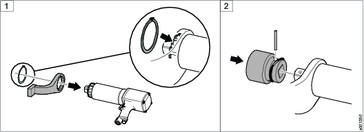
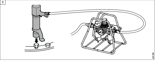
Connecting the tool and the FRL stand
-
Attach the reaction bar to the tool and insert the retaining ring into the groove to hold the reaction bar in position.
-
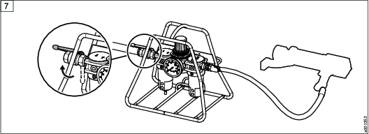
Attach the socket to the square drive. Insert the locking pin through the socket and square drive according to the illustration.
-
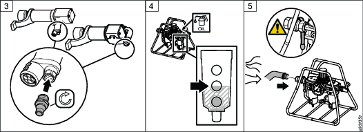
Attach the supplied Ergo nipple to the tool and tighten it to the correct torque.
-
Fill the optimizer with the provided oil up to the medium level. Refer to the optimizer instruction for details.
-
Before connecting the FRL unit to the main air supply:
Connect the main air supply hose to the FRL unit and tighten it correctly.
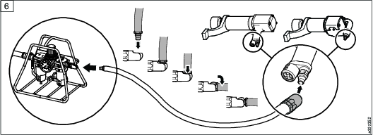
-
Connect the air hose supplied with the FRL unit. Insert the Ergo nipple into the Ergo quick coupling and turn it to a horizontal position according to illustration. Connect the other end of the hose to the tool.
-
Open the air input and main shutoff valves of the FRL unit.
-
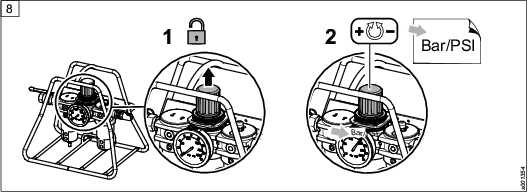
To adjust the air pressure on the FRL unit, unlock the control knob by pulling it up. Turn the control knob to adjust the air pressure according to the torque pressure chart.
-
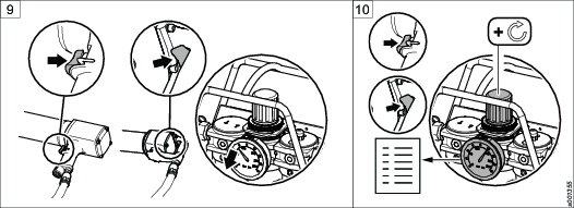
Push the trigger button on the tool to vent any existing air in the system.
-
Continue pushing the trigger button on the tool. Adjust the pressure at free speed using the control knob, according to the torque pressure chart.
-
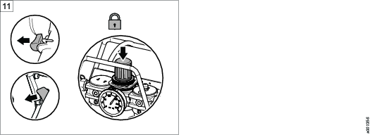
When you get the correct pressure, push down the control knob and release the trigger button.
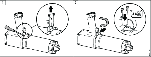
Installing the trigger guard
Required tools
-
Allen key
-
Remove the plastic plugs on the swivel unit, closest to the push button.
-
Put the trigger guard in position over the push button. Tighten the trigger guard with screws.
Operation
Ergonomic Guidelines
Consider your workstation as you read through this list of general ergonomic guidelines to identify areas for improvement in posture, component placement, or work environment.
Take frequent breaks and change work positions frequently.
Adapt the workstation area to your needs and the work task.
Adjust for a convenient reach range by determining where parts and tools need to be located to avoid static load.
Use workstation equipment such as tables and chairs appropriate for the work task.
Avoid work positions above shoulder level or with static holding during assembly operations.
When working above shoulder level, reduce the load on the static muscles by lowering the weight of the tool, using for example torque arms, hose reels or weight balancers. You can also reduce the load on the static muscles by holding the tool close to the body.
Take frequent breaks.
Avoid extreme arm or wrist postures, particularly during operations requiring a degree of force.
Adjust for a convenient field of vision that requires minimal eye and head movements.
Use appropriate lighting for the work task.
Select the appropriate tool for the work task.
In noisy environments, use ear protection equipment.
Use high-quality inserted tools and consumables to minimize exposure to excessive levels of vibration.
Minimize exposure to reaction forces.
When cutting:
A cut-off wheel can get stuck if the cut-off wheel is bent or not guided properly. Use the correct flange for the cut-off wheel and avoid bending the cut-off wheel during operation.
When drilling:
The drill might stall when the drill bit breaks through. Use support handles if the stall torque is high. The safety standard ISO11148 part 3 recommends using a device to absorb a reaction torque above 10 Nm for pistol grip tools and 4 Nm for straight tools.
When using direct-driven screwdrivers or nutrunners:
Reaction forces depend on the tool settings and joint characteristics. Strength and posture determine the amount of reaction force that an operator can tolerate. Adapt the torque setting to the operator's strength and posture and use a torque arm or reaction bar if the torque is too high.
In dusty environments, use a dust extraction system or wear a mouth protection mask.
Operating Instructions
Operating the tool with reaction bar
-
Attach the tool to the application.
-
By using the reverse lever, the tool can be operated in both clockwise and counter-clockwise directions.
-
Make sure the tool is placed in the correct position on the work surface as described in the picture. The end surface of the reaction bar and the socket/nut must be aligned. Make sure that the foot of the reaction bar hits the center of the nut that takes the reaction force.
-
Press the push button to start the tool.
-
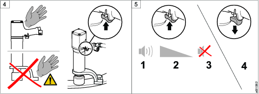
Continue pressing the push button while running down the nut. With pneumatic tools you can hear a sound, while the tool is running the nut down. When the sound decreases, release the push button to stop the tool. With electric tools the run down of the nut is controlled by the Power Focus.
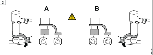
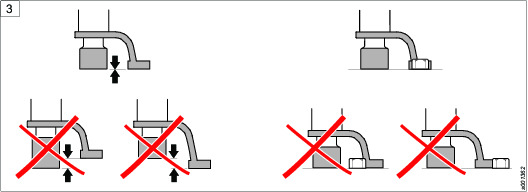
Using the reaction bar

Apply the reaction bar, opposite the direction of the drive of the product, before starting the product.
Service
Inspection of motor parts
Clean all parts before inspection.
End plates: Make sure that they are not scored or scratched. If the scratches are shallow, polish with fine grinding paste against a face plate. Clean thoroughly.
Rotor: Make sure that the end faces do not have any marks or burrs. Make sure that the hexagon drive is not damaged.
Cylinder: Make sure that the bore is not scored or scratched. If the scratches are shallow, polish with a fine grinding cloth. Clean thoroughly.
Maintenance Instructions
Service Recommendations
Preventive maintenance is recommended at regular intervals. See the detailed information on preventive maintenance. If the product is not working properly, take it out of service and inspect it.
If no detailed information about preventive maintenance is included, follow these general guidelines:
Clean appropriate parts accurately
Replace any defective or worn parts
Preventive Maintenance
Preventive maintenance
Daily maintenance: Visual inspection of all visible parts on the tool, including the reaction bar. Worn parts should be inspected thoroughly. If defects are found, the tool has to be repaired by qualified personel.
On a regular basis and when needed: make sure that the filter in the FRL unit is clean, the oil level is above minimum and no water is in the compressed air.
Inspection of silencer
Change or clean the filters regularly. Clogged filters will reduce power output.
Tightening of threaded connections
The tightening torque indicated in the exploded views in ServAid (see Spare parts section in https://servaid.atlascopco.com) will give the right clamping force and prevent threaded joints from loosening.
Retightening to the correct torque is needed on a regular basis, depending on application and usage.
For joints secured with Loctite, apply new Loctite when retightening.
Service instructions
Overhaul and preventive maintenance are recommended at regular intervals at least once a year or after 5 000 tightening operations, whichever comes first. More frequent overhauls may be required if the machine is used in heavy-duty applications. If the machine fails to function correctly, it must be taken out of operation immediately for inspection.
The strainer at the air inlet must be cleaned regularly in order to prevent clogging due to contamination. The machine capacity will otherwise be reduced.
All parts must be cleaned thoroughly during overhaul work and defective or worn parts must be replaced.
It is important that the threaded connections on the machine are tightened properly, see the exploded views. Lubricate the threads with grease prior to fitting.
All O-rings must be greased prior to assembly.
Always use an Atlas Copco FRL-unit for regulation of pressure oil mist, water separation and filtering.
Lubrication Instructions
Rust Protection and Cleaning
Water in the compressed air can cause rust. To prevent rust we strongly recommend to install an air dryer.
Water and particles can cause sticking of vanes and valves. This can be prevented by installing an air filter close to the product to avoid pressure drop.
Before longer stand stills always protect your tool by adding a few drops of oil into the air inlet. Run the tool for 5–10 seconds and absorb any access oil at the air outlet in a cloth.
For maximum performance
It is important to lubricate regularly to get maximum performance and trouble-free operation.
Use lubricants of good quality. The oils and greases mentioned in the table are examples of lubricants which are recommended.
Lubrication Guide
|
Brand |
General purpose, Bearings and Gears* |
|---|---|
|
BP |
Energrease LS-EP2 |
|
Castrol |
OBEEn UF 1 |
|
Esso |
Beacon EP2 |
|
Q8 |
Rembrandt EP2 |
|
Mobil |
Mobilegrease XHP 222 NLG 2 |
|
Klüber Lub. |
Klübersynth UH 1 14-151 |
|
Texaco |
Multifak EP2 |
|
Molykote |
BR2 Plus |
* Not for angle gears.
|
Brand |
Angle gears |
|---|---|
|
Molykote |
Longterm 2 Plus |
Lubrication guide
Valid lubricants:
Lubricant | Description |
|---|---|
A | Molycote Longterm 2 plus |
B | Q8 Chopin S46 |
C | Shell Gadus S2 |
Gear
Motor
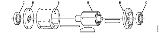
Motor housing
For Maximum Performance
At tough working conditions – soft joints and max. setting – lubrication of the air is recommended.
With extreme dry air the service life of vanes and machine performance might be reduced. A daily supply of 0.1 – 0.2 ml oil into the machine inlet will improve the machine performance. Alternatively consider an automatic lubricator device, Atlas Copco oil fog lubricator DIM, or single point lubricator DOS, which will improve the machine performance.
Dismantling/Assembling Instructions
Symbols

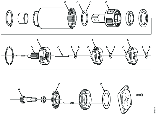
Dismantling the motor
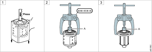
Model | ØD mm | Service tool | |
|---|---|---|---|
RTP1300/2600 | - | - | |
RTP4100/4100C HR25 | 19.8 | 4080 1463 01 |
Assembling the motor
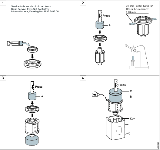
A
Model | ØD mm | Ød mm | L mm | Service tool |
|---|---|---|---|---|
RTP1300/2600 | 31.5 | 15.5 | - | 4080 0567 09 |
RTP4100/4100C HR25 | 41.5 | 20.5 | 15 | 4080 1463 00 |
B
Model | ØD mm | Ød mm | L mm | Service tool |
|---|---|---|---|---|
RTP1300/2600 | 45 | 41 | 60 | 4080 0207 02 |
RTP4100/4100C HR25 | 58 | 52 | 70 | 4080 0207 04 |
C
Model | ØD mm | Ød mm | L mm | Service tool |
|---|---|---|---|---|
RTP1300/2600 | 56 | - | 15 | 4080 0208 02 |
RTP4100/4100C HR25 | 68 | - | 10 | 4080 0208 03 |
Troubleshooting
Troubleshooting
The table describes the most common problems, possible reasons and actions to troubleshoot them.
Problem | Possible reason | Action |
|---|---|---|
Free speed is too slow, pressure never reaches the target. | Too low air flow in the pressurized air system. | Shorter hose to the FRL unit and larger diameter are needed. Check air flow for free speed in the specifications for the directions of required air flow at free speed. |
The tool cannot loosen a nut. | Corrosion and worn-out bolt and nut have affected the joint-loosening torque. | Apply a higher torque, within the torque chart spec. If it does not help, use a larger tool, if available, to remove the nut. Do not apply a higher pressure than specified, as it will shorten the service life of the tool. |
The tool has been flushed with a large amount of water. | The pressurized air system is affected by a large amount of condensed water. | See service recommendation for specific environments. |
Recycling
Environmental Regulations
When a product has served its purpose it has to be recycled properly. Dismantle the product and recycle the components in accordance with local legislation.
Batteries shall be taken care of by your national battery recovery organization.
Recycling information
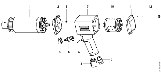
Pos. | Part | Remarks | Recycle as |
|---|---|---|---|
1 | Gear unit | Metal, steel | |
2 | Back plate | Metal, aluminum | |
3 | Screws | Metal, steel | |
4 | Trigger button | Plastics, other, PA | |
5 | Trigger | Metal, steel | |
6 | Retainer pin | Metal, steel | |
7 | Handle | Metal, aluminum | |
8 | Silencer | Metal, steel (contains small amounts of brass) | |
9 | Adapter | Metal, steel | |
10 | Vane motor* | Metal, steel | |
11 | Back plate | Metal, aluminum | |
12 | Screws | Metal, steel |
* The rotor vanes in the tool contains PTFE. Follow and observe the normal health and safety recommendations concerning PTFE.