P2506
Engraving pen
Product Information
General Information
Safety Signal Words
The safety signal words Danger, Warning, Caution, and Notice have the following meanings:
DANGER | DANGER indicates a hazardous situation which, if not avoided, will result in death or serious injury. |
WARNING | WARNING indicates a hazardous situation which, if not avoided, could result in death or serious injury. |
CAUTION | CAUTION, used with the safety alert symbol, indicates a hazardous situation which, if not avoided, could result in minor or moderate injury. |
NOTICE | NOTICE is used to address practices not related to personal injury. |
Warranty
Product warranty will expire 12+1 months after dispatch from Atlas Copco's Distribution Center.
Normal wear and tear on parts is not included within the warranty.
Normal wear and tear is that which requires a part change or other adjustment/overhaul during standard tools maintenance typical for that period (expressed in time, operation hours or otherwise).
The product warranty relies on the correct use, maintenance, and repair of the tool and its component parts.
Damage to parts that occurs as a result of inadequate maintenance or performed by parties other than Atlas Copco or their Certified Service Partners during the warranty period is not covered by the warranty.
To avoid damage or destruction of tool parts, service the tool according to the recommended maintenance schedules and follow the correct instructions.
Warranty repairs are only performed in Atlas Copco workshops or by Certified Service Partners.
Atlas Copco offers extended warranty and state of the art preventive maintenance through its ToolCover contracts. For further information contact your local Service representative.
For electrical motors:
Warranty will only apply when the electric motor has not been opened.
Website
Information concerning our Products, Accessories, Spare Parts and Published Matters can be found on the Atlas Copco website.
Please visit: www.atlascopco.com.
ServAid
ServAid is a portal that is continuously updated and contains Technical Information, such as:
Regulatory and Safety Information
Technical Data
Installation, Operation and Service Instructions
Spare Parts Lists
Accessories
Dimensional Drawings
Please visit: https://servaid.atlascopco.com.
For further Technical Information, please contact your local Atlas Copco representative.
Safety Data Sheets MSDS/SDS
The Safety Data Sheets describe the chemical products sold by Atlas Copco.
Please consult the Atlas Copco website for more information www.atlascopco.com/sds.
Country of Origin
For the Country of Origin, please refer to the information on the product label.
Dimensional Drawings
Dimensional Drawings can be found either in the Dimensional Drawings Archive, or on ServAid.
Please visit: http://webbox.atlascopco.com/webbox/dimdrw or https://servaid.atlascopco.com.
Overview
Technical Product Data
Technical Product Data can be found on either ServAid, or the Atlas Copco website.
Please visit: https://servaid.atlascopco.com or www.atlascopco.com.
Service Overview
Service Recommendations
Preventive maintenance is recommended at regular intervals. See the detailed information on preventive maintenance. If the product is not working properly, take it out of service and inspect it.
If no detailed information about preventive maintenance is included, follow these general guidelines:
Clean appropriate parts accurately
Replace any defective or worn parts
Installation
Installation Requirements
Air Quality
For optimum performance and maximum product life we recommend the use of compressed air with a maximum dew point of +10°C (50°F). We also recommend to install an Atlas Copco refrigeration type air dryer.
Use a separate air filter which removes solid particles larger than 30 microns and more than 90% of liquid water. Install the filter as close as possible to the product and prior to any other air preparation units to avoid pressure drop.
For impulse/impact tools make sure to use lubricators adjusted for these tools. Regular lubricators will add too much oil and therefore decrease the tool performance due to too much oil in the motor.
Make sure that the hose and couplings are clean and free from dust before connecting to the tool.
Both lubricated and lubrication free products will benefit from a small quantity of oil supplied from a lubricator.
Air Lubrication Guide
Recommended air lubricators:
Atlas Copco Optimizer (1 liter) 9090 0000 04
Q8 Chopin 46
Shell Air Tool Oil S2 A 320
Installation Instructions
Installation of Vibrating Tools
We recommend using a minimum length of 300 mm (12") of flexible hose for compressed air between a vibrating tool and the quick-action coupling.
Operation
Ergonomic Guidelines
Consider your workstation as you read through this list of general ergonomic guidelines to identify areas for improvement in posture, component placement, or work environment.
Take frequent breaks and change work positions frequently.
Adapt the workstation area to your needs and the work task.
Adjust for a convenient reach range by determining where parts and tools need to be located to avoid static load.
Use workstation equipment such as tables and chairs appropriate for the work task.
Avoid work positions above shoulder level or with static holding during assembly operations.
When working above shoulder level, reduce the load on the static muscles by lowering the weight of the tool, using for example torque arms, hose reels or weight balancers. You can also reduce the load on the static muscles by holding the tool close to the body.
Take frequent breaks.
Avoid extreme arm or wrist postures, particularly during operations requiring a degree of force.
Adjust for a convenient field of vision that requires minimal eye and head movements.
Use appropriate lighting for the work task.
Select the appropriate tool for the work task.
In noisy environments, use ear protection equipment.
Use high-quality inserted tools and consumables to minimize exposure to excessive levels of vibration.
Minimize exposure to reaction forces.
When cutting:
A cut-off wheel can get stuck if the cut-off wheel is bent or not guided properly. Use the correct flange for the cut-off wheel and avoid bending the cut-off wheel during operation.
When drilling:
The drill might stall when the drill bit breaks through. Use support handles if the stall torque is high. The safety standard ISO11148 part 3 recommends using a device to absorb a reaction torque above 10 Nm for pistol grip tools and 4 Nm for straight tools.
When using direct-driven screwdrivers or nutrunners:
Reaction forces depend on the tool settings and joint characteristics. Strength and posture determine the amount of reaction force that an operator can tolerate. Adapt the torque setting to the operator's strength and posture and use a torque arm or reaction bar if the torque is too high.
In dusty environments, use a dust extraction system or wear a mouth protection mask.
Operating Instructions
Changing from Stylus to Chisel
Loosen the cylinder sleeve from the inlet and the cylinder assembly (right-hand thread).
Remove the inlet and the cylinder assembly from the sleeve. Avoid damaging the O-ring.
Get the stylus out of the cylinder sleeve.
Make sure that the two O-rings are assembled under the shoulder of the anvil.
Drop the anvil into the cylinder sleeve (small end down). Shake the sleeve until the small end of the anvil enters the hole at the bottom of the sleeve.
Hardening Blank Chisels
A blank chisel is provided for special jobs. It can be heated and shaped into any desired form.
To harden the chisel after shaping, heat to cherry red and quench in oil. Polish a surface with emery cloth and reheat to a light straw color.
If heat treating facilities are available, harden by heating to 1550 °F for five minutes, quenching in oil and drawing at 425 ° for one hour. Hardness should be 55- 60 Re.
Sharpening the Stylus
For best results, use a diamond wheel mounted on a tool post grinder in a lathe. Polish first with a Norton stone No. 37C4006V or equivalent then with Carborundum paper No. A935K500 or equivalent to a 10-15 micro finish. If such facilities are not available, the stylus can be sharpened with No. 19A 60L8V Norton wheel on a bench grinder.
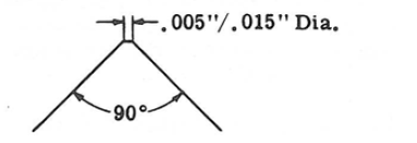
Sharpen to an included angle of 90 ° with a point diameter of • 005" to . 015" fiat.

The stylus may be sharpened until the turned down portion at the end of the stylus holder is ground off.
This gives a usable length of stylus of approximately 1/4 inch as shown on the drawing below .

Operating the Tool
To start the tool, turn the sleeve valve indicator approximately to the mid-point of the operating range. If necessary, jar the stylus lightly against the bench to start the piston. After starting, adjust the sleeve valve to the operating speed. The stylus will make a mark to the desired depth.
To turn on the tool, turn the sleeve valve clockwise.
To turn off the tool, turn the sleeve valve counter-clockwise.

This tool can mark material as hard as RC 64. When marking material of this hardness, make sure to regulate the impact of the stylus with the throttle valve so that the stylus makes a legible mark and no more than that. If the stylus is driven harder when working on very hard materials, there is a risk of excessive wear and breakage of the stylus point.
When operating the tool, do not bear down on the work and make stylus to dig in. Guide the tool and let the stylus do the work. The tool should be held approximately 15° off perpendicular to the work surface in order to scribe smoothly and to minimize excessive force on the side of the stylus point.
When using a chisel, it is necessary to bear the tool against the work as when working with a chipping hammer. Use the tool at full throttle on softer materials and adjust the speed to the job by varying the throttle setting. In this way, the operator is in full control of the tool. The amount of force that the operator exerts on the tool directly affects the chisel blow. Applying a lighter force when starting or stopping the work results in good control of the tool.
Service
Maintenance Instructions
Service Recommendations
Preventive maintenance is recommended at regular intervals. See the detailed information on preventive maintenance. If the product is not working properly, take it out of service and inspect it.
If no detailed information about preventive maintenance is included, follow these general guidelines:
Clean appropriate parts accurately
Replace any defective or worn parts
Maintenance

Do not dismantle safety-related parts. These parts should be completely replaced when damaged.
Make sure you follow the service instructions and the recommended service intervals.
Disassemble and inspect the tool every three months if the tool is used every day.
Replace any damaged, worn or improperly-functioning parts.
Maintenance and repair work must be carried out by qualified personnel using only original spare parts. Contact your Atlas Copco representative for advice on technical service or if you require spare parts.
Always ensure that the tool is disconnected from the energy source to avoid accidental operation.
Follow local country environmental regulations for safe handling and disposal of all components.
To keep downtime to a minimum, use a suitable service kit.
Lubrication Instructions
Lubrication
Use an air line lubricator with one of the recommended lubricators in the Air Lubrication Guide adjusted to two drops per minute.
Dismantling/Assembling Instructions
Dismantling the Tool
When disassembling the tool, use a 3/32" pin punch to remove the roll pin.
Support the tool firmly on a suitable surface and drive the pin out carefully to avoid damage to the cylinder or to the inlet. Do not lose the roll pin. When removing the sleeve valve, align the mark on the sleeve with OFF on the inlet to avoid cutting the O-ring.
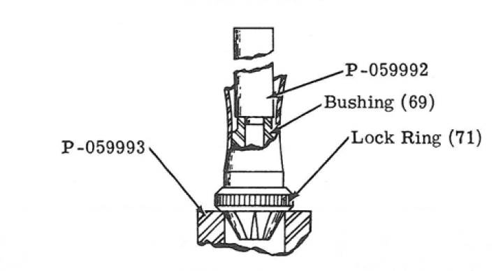
To remove the accessory bushing support lock ring on the bore of the P-059993 holder, press the bushing out of the cylinder sleeve from the inside of the sleeve with P-059992 drift.

Assembling the Tool
When assembling the inlet with sleeve valve (14"), first lubricate the O-ring lightly with a good rubber lubricant and place it in a counterbored air port in inlet. Lubricate the two O-rings and assemble them in the grooves on either side of the air port. To avoid cutting the O-rings in the air port, align the indicator mark on the valve with the OFF on the inlet and slide the valve carefully on the inlet. Place the retaining ring in the groove in inlet, lubricate a third O-ring and assemble the in groove next to the shoulder between the retaining ring groove and the threads on the inlet. Make sure this O-ring is assembled between the slight ridge and the shoulder to prevent the O-ring from being forced into the inlet threads.
When installing a new piston in the cylinder, it may be necessary to lap the piston to secure a close and free fit in the cylinder. No. 12-24 UNC internal threads in the piston allow handling during this operation. Use a good grade fine lapping compound, thoroughly clean the parts and lubricate with the recommended air tool oil before assembly.
After assembling the piston and cylinder, lubricate and install the O- ring on the inlet and carefully slip the cylinder on the inlet. Do not damage the O-ring. Align the transverse holes in the cylinder and the inlet and carefully install the roll pin through the parts. Support the parts firmly and avoid damaging the parts while driving the roll pin.
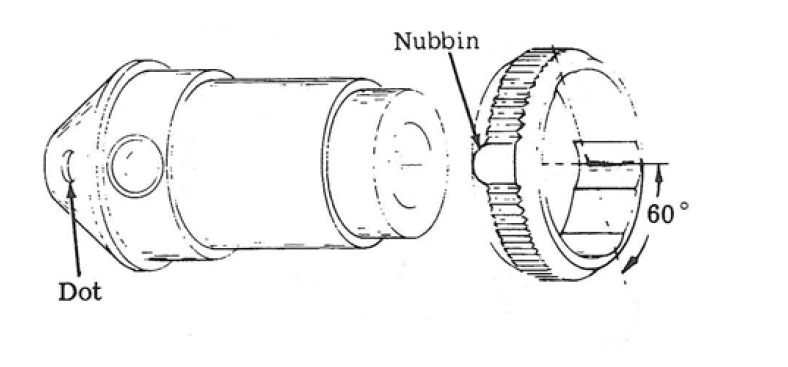
Assemble the O-ring and the 1/8'' steel ball in the accessory bushing with lubricant to hold in place. Lubricate and assemble the 5/32" steel ball in the larger opening. Refer to the illustration below to align the nubbin at a smooth spot on the Iock ring with dot on the accessory bushing. The nubbin should be on the side of the lock ring toward the bushing. Slip the ring on the bushing. Orient the dot on the bushing with any corner of the hex. on the cylinder sleeve and press the bushing into the sleeve up to the bushing shoulder.

Troubleshooting
Troubleshooting
Due to the close clearance between the piston and the cylinder, external matter in the air supply may cause the piston to stick. To avoid this issue, remove the cylinder sleeve, drive the roll pin out of the cylinder and inlet, and remove the piston from the cylinder. Thoroughly clean all parts, blow dry and lubricate with the recommended air tool oil. Check the clearance and the free movement of the piston and reassemble the tool.
To remove the sleeve valve, remove the O-ring between the retaining ring and the threads on the inlet, remove the retaining ring, set the sleeve valve to OFF and pull the valve off the inlet. Inspect the O-rings, replace if worn, re-lubricate and re-assemble. Do not over-lubricate the O-ring in the counterbored air port, there is a risk of impeding the air flow.
Recycling
Environmental Regulations
When a product has served its purpose it has to be recycled properly. Dismantle the product and recycle the components in accordance with local legislation.
Batteries shall be taken care of by your national battery recovery organization.