STRwrench Firmware (3.7)
Introduction
In this section, you can find the basic information about the product and also the formatting conventions used in the topics.
General Data Protection Regulation (GDPR)
This product offers the possibility to process personal identifiable information such as system user name, role and IP-address. The purpose of this processing capability could be to enhance quality control through traceability and proper access management.
If you decide to process personal data you need to be aware of and comply with relevant personal data protection rules, including, in the EU the GDPR as well as other applicable laws, directives and regulations. Atlas Copco can in no way be held liable for any use made by you of the product.
Liabilities and Warnings
Liability
Many events in the operating environment may affect the tightening process and shall require a validation of results. In compliance with applicable standards and/or regulations, we hereby require you to check the installed torque and rotational direction after any event that can influence the tightening result. Examples of such events include but are not limited to:
initial installation of the tooling system
change of part batch, bolt, screw batch, tool, software, configuration or environment
change of air- or electrical connections
change in line ergonomics, process, quality procedures or practices
changing of operator
any other change that influences the result of the tightening process
The check should:
Ensure that the joint conditions have not changed due to events of influence.
Be done after initial installation, maintenance or repair of the equipment.
Occur at least once per shift or at another suitable frequency.
Warnings
About the User Guide
This user guide describes how to set up and configure the STRwrench using the STRwrench user interface.
Revision History
Release Number | Revision Date | Revision Description |
|---|---|---|
3.7 | 02-2022 | NEW content:
|
3.6 | 06-2021 | NEW content:
|
1.0 | 03-2021 | First edition. |
Target group
This user guide is intended for anyone configuring or operating an STRwrench using its web user interface.
Prerequisites
Anyone interested in learning more about the STRwrench web user interface can benefit from reading this user guide.
For a complete understanding of the technical aspects in the user guide the following is recommended:
Knowledge about tightening techniques
Experience of working with Power Focus 6000 or Power Focus 4000
For more information about Power Focus 6000 and Power Focus 4000, refer to the Power Focus 6000 User Guide and the Power Focus 4000 User Guide.
Conventions
To enhance user understanding, certain formatting conventions are used throughout this document. The formatting conventions used are listed below.
Element | Notation | Description | Output |
|---|---|---|---|
General emphasis | In the Program workspace. | To make certain text elements stand out, or to highlight. | Text in Bold |
Graphical User Interface (GUI) items | Select the Function button. | Any reference to items found on screen in the GUI (for example, command buttons, icon names and field names). | Text in Bold |
Graphical User Interface (GUI) Path > | Generally, on the top of the GUI. | Navigation aid which keeps track of the location in the GUI. | For example: Controller > Program > Edit |
User input | Enter a Description for the program. | Any text input by the user. | Text in Bold |
File names | Enter a File Name for the export. | Files either exported from, or imported into the system. | Text in Bold Italic |
Variable and parameter names | Enter a Name for the export. | Variable and parameter names (not values). | Text in Italic |
Variable and parameter values | Enter a VALUE for the export. | Variable and parameter values. | Text in BOLD CAPS |
System output | Client.Domain.Models.ExportImportConfiguration | Any text output by the system. | Text in Monospace |
External links | Links to external sites that have information connected to the document or subject content. These could include:
| Selectable text to external sites | |
Internal documentation links |
If available, these links will be presented below the text. | Selectable text to internal content |
System Overview
A manufacturing system may consist of the functional blocks in the figure:
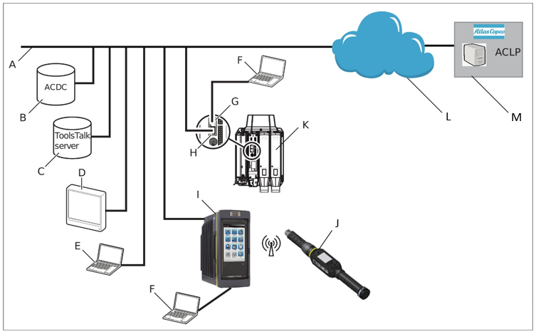
A | Factory network. | H | Controller factory port: connected to the factory network. |
B | ACDC: for storing tightening results and for statistical analysis. | I | Power Focus 6000 / Power Focus 4000 controller: used with handheld tools. |
C | ToolsTalk 2 server: for configuration and parameter settings for controllers and tools. | J | STRwrench: uses a wireless connection to the controller. |
D | Industrial PC (IPC): can be used as client terminal to the ToolsTalk 2 and ToolsNet servers. | K | PF6 Flex controller: used with fixtured tools. |
E | Portable computer connected to the factory network: can be used as client terminal to the ToolsTalk 2 and ToolsNet servers. | L | The internet cloud. |
F | Service computer: can be connected to the service port of a controller or STRwrench. | M | Atlas Copco Licensing Portal (ACLP): located at Atlas Copco and provides support to licensed functionality in the Functional Management System (FMS). |
G | Controller service port: can be used to connect a service computer. |
The User Interface
Home menu
The home menu contains the following items:
Menu Item | Description |
|---|---|
 | Integrated Controller Tool This menu includes items such as:
|
 | Reports Displays the latest events. |
 | Settings This menu is used to set up specific settings such as:
|
Installation and Upgrade
In this section, you can find information to help with the initial installation of the product, or upgrading from one version to another.
Installation Restrictions
Web Browser Requirements
The following web browsers are recommended for the STRwrench web user interface:
Firefox
Google Chrome
Microsoft Edge
Upgrading
Firmware Versions
Two firmware versions can be installed in the tool simultaneously. Installing a second version of the firmware is useful when performing upgrades on multiple tools. When production is ready for switching to the upgraded firmware, activation of the new version is done from the STRwrench Web User Interface .
Changing firmware versions does not transfer the tool configurations or tightening programs.
Software Activation
The tool can store two installed firmware versions. By using the Software activation, it is possible to choose which firmware version to use.
Make sure to keep the battery connected to the tool throughout the procedure.
Go to Integrated Controller Tool in the home menu and select Software in the left pane.
Select Current or Stored in the Software Activation window.
The tool is automatically restarted for the activation to take effect.
Update Software Version
Make sure to keep the battery connected to the tool throughout the procedure.
Go to the Integrated Controller Tool menu and select Software in the left pane.
Go to the Software Update field and select BROWSE.
Browse and choose the zip file with the applicable software and follow the instructions to finish installation.
Rescue Mode
After three unsuccessful restarts the tool will enter Rescue Mode. In this mode it is possible to update the firmware and/or perform disk management.
Connect the tool to the USB port of the PC. Open a web browser and type in the address 169.254.1.1.
In the Rescue Mode user interface, go to the Software Update tab.
Select the file system to be updated and browse for the correct file.
Select the Update button.
Go to the Power tab and reboot the system.
Connect the tool to the USB port of the PC. Open a web browser and type in the address 169.254.1.1.
In the Rescue Mode user interface, go to the Disk Management tab.
Choose to repair file system or clean data, as appropriate.
Select the Submit button.
Go to the Power tab and reboot the system.
Configuration
In this section, you can find detailed information about how to create, modify, and verify product settings.
Configuration options
The configuration and setting up of the tool must be done as follows:
STRwrench web user interface: The tool can be directly connected to a PC via a USB cable. If the tool is connected to a wireless network and its IP address is known, it can be accessed from a computer anywhere on the network.
Controller: This is applicable to Power Focus 6000 and Power Focus 4000 controllers. A controller can be configured regardless whether it is connected to the network or not.
This user guide covers the STRwrench web user interface. For information about Power Focus 6000 and Power Focus 4000, refer to Power Focus 6000 User Guide and Power Focus 4000 User Guide.
Getting Started
To create a better overview of the system, this section provides a quick guide covering the basic steps required to get started with the STRwrench and STRwrench Web Interface . The section does not explain every feature of the system, but instead focuses on the most basic ones.
Connect the tool to a PC and access the web user interface. Set up a wireless connection between the tool and the Power Focus.
On the Power Focus, define a tightening program containing all relevant parameters of a tightening, for example target angle and target torque.
If applicable, create a batch sequence. One or several tightening programs can be added to a batch sequence which works as a series of tightening programs. A batch sequence can for example be a certain number of tightenings with a tightening program, or a sequence of different tightening programs.
Assign a tool and a task to the virtual station. The task can be either a tightening program, a batch sequence, or a specified digital input (from for example a barcode scanner).
Accessing the STRwrench Web Interface
Remove the cover of the tool's USB connection port.
Connect the tool to the USB-port of the PC.
Open a web browser and type in the address 169.254.1.1.
To access the user interface wirelessly, refer to the instructions in the section Configure a Wireless Client.
Working with the Configurations Tab
Configurations of the tool and its accessories are made in the Configurations menu.
Tool Configuration
The following section describes how different tool functions, such as LEDs and buttons, can be configured.
General Settings
Item | Description |
|---|---|
Front LED | On: Front LED is lit when the dedicated button is pressed. Off: Front LED will always be off. |
TAG | On: Information on the TAG is displayed and can be edited in the Integrated Controller Tool > Tool menu. Off: Information on the TAG will not be displayed. |
Buzzer | On: Audio signaling device will always be on. Off: Audio signaling device will always be off. |
Vibration | On: Vibrating device will always be on. Off: Vibrating device will always be off. |
Loose before cycle start | On: Accidental unscrewing of an already tightened joint is detected before the tightening starts. Off: Function deactivated. |
Working with the Integrated Controller Tool Tab
Tool
View Tool Information
Go to Integrated Controller Tool in the home menu and select Tool in the left pane.
Expand the Tool Information field to view the following information:
Information
Description
Model
Controller model denomination.
Serial number
The serial number of the controller may be needed when for the correct spare parts list or service instructions.
Product number
The product number of the controller.
TAG Information
Go to Integrated Controller Tool in the home and select Tool in the left pane.
Expand the TAG Information field. The following information is displayed:
Parameter
Description
TAG ID
TAG number.
Torque Correction Coefficient
Torque correction coefficient defined for the TAG.
Angle correction
Angle correction defined for the TAG.
Nominal torque
Torque at which the Angle correction is defined.
Maintenance
Go to Integrated Controller Tool in the home and select Tool in the left pane.
Expand the Maintenance field. The following information is displayed:
Parameter
Description
Is the transducer overloaded?
Yes - the transducer has been overloaded.
No - the transducer has not been overloaded.
Highest torque value
Highest torque output measured by the transducer.
Highest torque date
Date and time when the highest torque output was measured by the transducer.
smartHEAD Information
Go to Integrated Controller Tool in the home and select Tool in the left pane.
Expand the smartHEAD Information field. The following information is displayed:
Parameter
Description
Model
smartHEAD model denomination.
Max torque
The maximum torque the smartHEAD can use for a tightening.
Serial Number
The serial number of the smartHEAD may be needed when for the correct spare parts list or service instructions.
Product Number
The product number of the smartHEAD.
Firmware Versions
Two firmware versions can be installed in the tool simultaneously. Installing a second version of the firmware is useful when performing upgrades on multiple tools. When production is ready for switching to the upgraded firmware, activation of the new version is done from the STRwrench Web User Interface .
Changing firmware versions does not transfer the tool configurations or tightening programs.
Exporting and Importing Configurations
The export and import functions are used to export events and tightening results for analysis in external programs, as well as allowing for transferring of tightening programs, batches, and tool configurations between tools.
The export function is used to:
Export tightening results and events for further processing.
Export log files for debug assistance from an Atlas Copco service engineer.
Export tool configuration that can be used to copy settings to another tool.
Go to Integrated Controller Tool in the home menu. Select Export/Import in the left pane.
Select what to export from the tool: All information or Settings and configurations.
When Settings and configurations is chosen no file with results or events will be exported into the archive. With this setting the export takes less time to perform.
Select EXPORT. A prompt to select where to save or retrieve the exported file is shown.
Go to Integrated Controller Tool in the home menu. Select Export/Import in the left pane.
Select IMPORT. When using the import function, all settings for tightening program, batch, accessories, and tool are replaced by the settings from the import file. However, settings for network, PIN, and results and events are not imported.
Select CONTINUE in the dialog box to start the import.
Exported information and File Format
The exported file is a compressed file archive containing the following files:
All information
STRwExport_<datetime>_Events.csv
ExportInfo.txt
settings/settings.bin
atlas_sys_i.zip
atlas_plc.zip
jsonConfigurations.zip
Settings and configurations
ExportInfo.txt
settings.zip
jsonConfigurations.zip
File | Description |
|---|---|
STRwExport_<datetime>_Events.csv | A semicolon-separated file containing the following information:
|
ExportInfo.txt | Information about the tool set-up and tool software. |
settings/settings.bin | A binary file containing all tightening programs and Batch settings, Accessory configurations, and tool settings such as: Language, Torque units, Date and time, and Result appearance. |
atlas_sys_i.zip | Log files from IT application. |
atlas_plc.zip | PLC configuration. |
jsonConfigurations.zip | Multistep Tightening and Loosening programs. |
Depending on the language setting in the STRwrench Software, the exported .csv file uses different characters to separate the fields. Depending on the language setting in the computer, formatting problems may occur when opening the exported .csv file. To avoid problems, always match the language used in the tool with the language of the computer.
See the following table for language formatting details of the STRwrench Software:
Language | Date/time | Field delimiter | Number format |
|---|---|---|---|
English (en_US) | MM/dd/yyyy hh:mm:ss | , | 123.456 |
Czech (cs_CZ) | dd.MM.yyyy hh:mm:ss | ; | 123,456 |
German (de_DE) | dd.MM.yyyy hh:mm:ss | ; | 123,456 |
Spanish (es_ES) | dd/MM//yyyy hh:mm:ss | ; | 123,456 |
French (fr_FR) | dd/MM/yyyy hh:mm:ss | ; | 123,456 |
Korean (ko_KR) | yyyy-MM-dd hh:mm:ss | , | 123.456 |
Italian (it_IT) | dd/MM/yyyy hh:mm:ss | ; | 123,456 |
Japanese (ja_JP) | yyyy/MM/dd hh:mm:ss | , | 123.456 |
Portugese (pt_BR) | dd/MM/yyyy hh:mm:ss | ; | 123,456 |
Russian (ru_RU) | dd.MM.yyyy hh:mm:ss | ; | 123,456 |
Swedish (sv_SE) | yyyy-MM-dd hh:mm:ss | ; | 123,456 |
Chinese (zh_CN) | yyyy/MM/dd hh:mm:ss | , | 123.456 |
Working with the Settings Tab
Network Configurations
The tool can be set up to be accessed wirelessly from a web browser on a Local Area Network (LAN), using IPv4 protocol.
There is an option to use the tool as a client or an access point for other devices.
Remove the cover of the tool's USB connection port.
Connect the tool to the USB-port of the PC.
Open a web browser and type in the address 169.254.1.1.
Configuring Channels
Go to Settings in the home menu and select Network in the left pane.
In the Channels field, choose frequency (2.4 GHz or 5 GHz) and select Edit.
Choose to enable or disable channels.
Configuring a Wireless Client
Go to Settings in the home menu and select Network in the left pane.
In the Wireless Client field, select Edit.
Set Enabled to On.
Set DHCP to On or Off depending on the configuration. If set to Off, fill out the required information, provided by the local system administrator:
IP address
Subnet mask
Gateway
Enter a Network name (SSID).
In the Security field, select Mode and choose a security mode from the list. If WPA2 Personal is chosen, enter a Security key.
Enter security parameters and import cert files and keys, as applicable.
Edit the Optional Settings as applicable.
Select Apply.
The tool will establish a wireless connection to the network, indicated with the tool's blue connection LED indicator emitting a steady light.
To access the user interface wirelessly, type the IP address into a web browser.
Configuring the Tool as a Wireless Access Point
If multiple channels have been configured previously in Wireless Client mode, enabling Wireless AP mode will update the channel list to contain only the current/default channel for the Wireless AP mode.
Go to Settings in the home menu and select Network in the left pane.
In the Wireless AP field, select Edit.
Set Enabled to On.
Enter the required information, provided by the local system administrator:
IP address
Subnet mask
Gateway
To distribute IP addresses, set DHCP Server to On and enter IP range start and IP range stop.
Enter a Network name (SSID).
In the Security field, select Mode and choose a security mode from the list. If WPA2 Personal is chosen, enter a Security key.
Select Apply.
Server connections
The tool can be set up to communicate with:
Power Focus 6000 − used to define tightening programs and batch sequences
Power Focus 4000 − used to define tightening programs and batch sequences
Configuring the Power Focus Connection
Go to Settings in the home menu and select Server Connections in the left pane.
In the Power Focus field, set the following parameters:
Field
Description
On/Off
Enables/Disables communication with the Power Focus.
Server port
Power Focus port.
Server host
Power Focus IP address.
Select Apply.
Preferences
Date and Time
Date and time must be set in order for events and results to get the correct time stamp for when they occurred. The time is retrieved from one of three available sources:
Manual − the date, time, and time zone are set manually.
NTP − the date and time are retrieved from an NTP (Network Time Protocol) server defined in the user interface.
Go to Settings in the home menu and select Preferences in the left pane.
In the Date and Time field, set the following parameters:
Parameter
Description
Source
Source to retrieve the time from.
NTP Server 1
IP-address of an NTP server providing date and time for the tool.
Server 1 status
OK/No Status
NTP Server 2
IP-address of an NTP server providing date and time for the tool.
Server 2 status
OK/No Status
Date
Date entered manually if the source is set to manual.
Time
Time entered manually if the source is set to manual.
Time zone
The time zone; either the location or a standard time zone such as UTC (coordinated universal time)
Select APPLY.
Setting Language
The user interface is available in the following twelve languages:
English
Czech
German
Spanish
French
Korean
Italian
Japanese
Portuguese
Russian
Swedish
Chinese
Go to Settings in the home menu and select Preferences in the left pane.
In the Language field, select the language currently in use and choose a language from the list.
The language change will take effect immediately.
Configuring Events
Each event has a default setting for whether it is to be acknowledged (ACK), logged (LOG), or displayed (DISP).
Some options cannot be changed. They are greyed out.
Go to Settings in the home menu and select Events in the left pane.
Select Configure events.
Search for the event to be configured by typing the event code in the Search field and pressing Enter.
Tick or untick the boxes ACK., LOG. and DISP., as desired.
If applicable, add information about the event in the DETAILS field.
Reports and Statistics
In this section, you can learn about available reports and statistics.
Working with the Reports Tab
Viewing Events
Events are used to notify the user of certain state changes or occurrences in the system. They are divided into three types; Information, Warnings and Errors and require different kinds of actions.
Each event occurred is stored in the event log.
Go to Reports in the home menu and select Results in the left pane.
Select View all events.
Select an event in the list to open the event dialog box.
Event Codes
Events are used to notify the user of certain state changes or occurrences in the system. They are of different types and require different kinds of actions.
Some of the procedures described can only be performed by an Atlas Copco authorized service provider.
Event Code Groups
The event codes can be divided into the following groups:
Event code | Group | Description |
|---|---|---|
1000-1999 | Controller, Tool | Controller and Tool events. |
2000-2999 | Tool | Tool events. |
3000-3999 | Controller, Drive, Channel, Configuration | Controller and Drive events, and Step sync events. |
4000-4999 | Process | Tightening process events. |
5000-5999 | Configuration | Program configuration events. |
6000-6999 | Accessory | Accessory events. |
7000-7999 | Message | Messages. |
Event Code List Description
The following table describes the information in the event code list:
Item | Description | |
|---|---|---|
Event code | The unique event number. | |
Type | Type of event:
| |
Name | A descriptive name of the event. | |
Description | A short description of the event and why it occurred. | |
Procedure | If applicable the procedure contains an instruction on how to clear the event. | |
Event Code List
Event | Description | Procedure | ||
|---|---|---|---|---|
Code | Type | Name | ||
1000 | Info | Controller started | The controller is started. | N/A |
1001 | Warning | Controller serial number updated | Generated at start-up if IT-board box serial number (controller serial number) differs from AUX-board box serial number. AUX-board is considered to be non-replaceable in field. The controller will reboot when the serial number is updated. | Replace IT-board or box. |
1010 | Info | Tool connected | A tool is connected. | N/A |
1011 | Info | Tool disconnected | A tool is disconnected. | N/A |
1012 | Info | Tool connection rejected | OpenProtocol tool rejected controller connection. | Check if another controller is connected to the tool. |
2000 | Warning | Battery low |
| Replace battery. |
2001 | Warning | Battery empty |
| Replace battery. |
2002 | Warning | Tool battery health low | Tool battery health problem is detected. | Replace battery |
2004 | Warning | Tool is not of the preferred type | Tool has been replaced by a tool with a different Tool max torque. | Change tool |
2006 | Warning | Tool backup battery health low | The backup battery in the tool has too poor performance. | The backup battery should be replaced. |
2007 | Warning | Tool backup battery missing | Tool backup battery is missing. | Insert battery |
2008 | Warning | Tool backup battery error | Tool backup battery error detected. | Replace battery |
2009 | Warning | Backup battery voltage low | The controller's backup battery is almost empty | Replace battery |
2010 | Error | Tool software version mismatch | Tool and controller software versions not compatible. | Service tool - update tool software. |
2012 | Warning | Tool communication disturbance | Communication between tool and controller interrupted. | Relocate antenna placement. |
2013 | Warning | Illegal ring position | Tool direction switch in faulty position. | If occurring frequently - service tool. |
2014 | Warning | Tool overheated | Tool overheated. | Allow tool to cool down. |
2015 | Error | Tool temperature sensor error |
| Service tool. |
2016 | Warning | Tool pulse unit overheated | Tool pulse unit overheated. Tool is not locked, but the warning is displayed whenever the tool is started as long as the pulse unit temperature is over threshold. | Allow tool to cool down |
2019 | Warning | Tool could not start motor | Tool motor failure. | |
2020 | Warning | Tool requires motor tuning | Tool requires motor tuning. | Perform a motor tuning. |
2021 | Warning | Motor tuning failed | Motor tuning failed. | Complete motor tuning or service the tool. |
2022 | Info | Motor tuning completed | Motor tuning completed. | N/A |
2023 | Warning | The tool requires open end tuning | The tool requires open end tuning. | Perform open end tuning. |
2024 | Warning | Open end tuning failed | Open end tuning failed. | Try to perform open end tuning one more time. If it fails again, service the tool. |
2025 | Info | Open end tuning successful | Open end tuning successful. | N/A |
2026 | Warning | Open end position failed | Open end position failed. | Press the trigger again and wait for the positioning to be completed. If it fails again, service the tool. |
2027 | Warning | Usage limited due to high tool temperature | Temperature limit has been reached. Tightening has been inhibited to reduce risk for tool shutting down due to overheating. | Wait until tool temperature has been reduced. |
2030 | Error | Tool memory failure, change tool | Tool memory corrupt. | Service the tool. |
2031 | Error | Tool accessory memory corrupt | Tool accessory memory corrupt. | Service the tool accessory. |
2040 | Error | System check failure |
| |
2041 | Error | Torque transducer error | Will be generated either on calibration error or if tool reports transducer error. | Service the tool. |
2042 | Error | Angle transducer error |
| Service the tool. |
2043 | Error | Tool ground fault error |
| Service the tool. |
2044 | Info | Tool service interval expired | Indicates that servicing of the tool is needed. Triggered when the number of set tightenings has been exceeded. | Perform service of tool. |
2045 | Warning | Tool calibration data invalid | If validation of calibration data fails. | Service tool. |
2046 | Info | Tool, next calibration date has passed | Indicates that calibration of tool is needed. Triggered when calibration alarm is enabled in settings and the current time is greater than next calibration date. | Service tool. |
2047 | Info | Auto update of servicedata checksum | Indicates that service data checksum has been updated automatically. | N/A |
2048 | Info | Tool calibration value updated by QA device | Tool calibration was updated when a calibration with a QA device was performed | |
2050 | Error | Tool parameter file not supported | Required tool parameters are missing. | Update tool parameters. |
2060 | Info | Unexpected trigger behavior | Used to prevent start of tool if accessory is connected. | N/A |
2071 | Error | Tool memory corrupt | Tool descriptor is corrupt. | Service the tool. |
2072 | Info | Unknown device connected |
| |
2073 | Warning | Tool trigger supervision failure | HW channel failure. Mismatch between hardware and software of tool trigger. | |
2074 | Warning | Tool indicator board failure | Tool indicator board failure. | Service the tool. |
2075 | Warning | Tool fan voltage failure | Tool fan voltage failure. | Service the tool. |
2076 | Warning | Tool accessory bus voltage failure | Tool accessory bus voltage failure. | Service the tool. |
2077 | Warning | Tool trigger sensor error | Tool trigger sensor error. | Service the tool. |
2078 | Info | Tool Tightening program updated | Tool locked due to tightening program update. | |
2079 | Error | Tool cable not supported | Tool cable is corrupt. The chip in the cable is not responding or is damaged. | Switch cable. |
2080 | Error | Tool battery failure | DC voltage too high or too low. Battery failure. | Contact the Atlas Copco service representative and send back battery to Atlas Copco (do not reuse it!). |
2081 | Error | Tool current limit reached | The current limit has been reached and the drive is disabled. | Service the tool. |
2082 | Error | Tool current measurement error | Current measurement error. Current cannot be measured with a reliable result. | Service the tool. |
2083 | Error | Tool internal error | Various internal hardware errors. | Service the tool. |
2084 | Error | Tool internal software error | Various internal software errors. | Service the tool. |
2085 | Error | Tool RBU error | An RBU error was detected by the tool software. | Check that the RBU is correctly installed. If error is still present then service the tool. |
2086 | Error | Tool stall | Tool motor is stalling. | Service the tool. |
2087 | Warning | Tool motor current high | Tool motor current limit is exceeded, and the tool is locked. Tool will enter failsafe mode. | |
2088 | Warning | Tool battery current high | Tool battery current is too high. | |
2089 | Warning | Tool drive voltage low | Tool drive voltage is below the monitored lower voltage limit. | |
2090 | Warning | Tool drive voltage high | Tool drive voltage is above monitored higher voltage limit. | |
2091 | Warning | Tool main board error | Tool main board internal error. | |
2092 | Warning | Tool power module error | Tool power module internal error | |
2093 | Warning | Pulse unit oil level low | The oil level of the connected pulse tool is low. | Service the tool |
2094 | Warning | Pulse unit oil level empty | The oil level of the connected pulse tool is below required operational level | Service the tool |
2095 | Warning | Tool battery communication lost | Tool lost communication with battery. | Make sure battery is seated correctly. Otherwise change battery |
2096 | Error | Tool battery software version mismatch | Tool battery software incompatible with tool software. | Update software. |
2100 | Info | STwrench smartHead removed | STwrench smartHead has been removed. | Reconnect smartHead and restart the wrench. |
2101 | Warning | Wrench tightening when locked | A wrench tightening was performed when the tool status was locked in the controller. | Wait until the tool status in controller is unlocked. |
3000 | Error | Controller internal software error | Software error in the controller. | Contact service. |
3001 | Error | Controller clock battery empty | Internal battery is getting close to end of life. | Replace battery |
3010 | Warning | System overheated | The controller is overheated. | Cool down. |
3011 | Warning | Drive overheated Controller hardware | Cool down. | |
3013 | Warning | Usage limited due to high controller temperature | Temperature limit has been reached. Tightening has been inhibited to reduce risk for controller shutting down due to overheating. | Wait until controller temperature has been reduced. |
3020 | Warning | Controller hardware failure | ||
3021 | Warning | System voltage problem | DC voltage too high or too low. | N/A |
3030 | Error | IP address conflicting with another node on the network | The set IP address is in use by another device on the same network. | Change IP address on one of the devices. |
3031 | Info | Network cable unplugged | The carrier of the factory port is lost (cable disconnected). | Check the cable connection. |
3032 | Info | Pairing started | Tool pairing started. | N/A |
3033 | Info | Pairing successful | Tool pairing successful. | N/A |
3034 | Error | Pairing unsuccessful: no tool found | The controller found no tool to pair with when scanning for radio peers. | Set the tool in pairing mode and try again. |
3035 | Error | Pairing unsuccessful: more than one tool found | The controller found more than one tool when scanning for radio peers. | Ensure that only one tool is in pairing mode when starting the pairing mode on the controller. |
3036 | Error | Pairing unsuccessful: Communication error | The controller experienced a loss of connection, an unexpected answer or timeout during the pairing process. | Try to perform pairing one more time. If it fails again, service the tool. |
3037 | Info | Pairing unsuccessful: Tool slot is full | Clear one tool slot | |
3040 | Warning | Emergency stop | Drive disabled due to emergency stop. | Reset emergency stop. |
3050 | Info | System clock updated | System clock has been updated. | N/A |
3051 | Error | System clock error | Wrong time read from hardware Real Time Clock (RTC). | Change RTC battery. |
3052 | Warning | Remote start configuration error | Mismatch between HW and SW remote start configuration. | Check and verify that HW dip switch matches the selected start source. |
3053 | Info | Drive connected | StepSync drive has been connected. | |
3054 | Info | Drive disconnected | StepSync drive disconnected. | |
3055 | Warning | Mode configuration error | Generated when selected mode is configured wrongly. E.g. configuring two bolts with the same bolt number or the same channel, incomplete mode configuration | Check Toolstalk2 for mode configuration error |
3056 | Warning | Unable to start, tool or drive is missing | Generated when a used channel is missing a drive or tool. | Check Channel Menu on the HMI. Connect missing drive or tool. |
3057 | Info | Unable to start, channel is already in use | Generated when a needed channel has been allocated to another virtual station | |
3058 | info | No mode selected | Select mode | |
3059 | Warning | Failed to connect to Atlas Copco License Manager | Indicates that the controller failed to connect to the local license manager to get licenses. | Check local network. If it fails again, service the controller. |
3084 | Error | Soft PLC runtime error | eCLR has terminated in an uncontrolled way. | |
3150 | Error | Software IAM incompatibility | IAM is incompatible with the software installed on the controller. | Replace IAM. |
3160 | Error | Failed to activate newly installed software | Something went wrong during the activation. When the newly installed software starts, a fallback to the previous working software happens. This happens when the new software fails to start for three times and only during software installation. | Take an export and contact Atlas Copco for further assistance. Note down the software version you are trying to install as well as the software version that is working. |
3161 | Error | Started on unexpected software partition | The controller has started on the inactive software side and not on the expected software side. | Note down the software information (on the Home page of the controller, select Controller > Software). Try to restart the controller and make sure its running on correct software when started again. If error persists, do an export and contact Atlas Copco. |
3500 | Error | Generic license manager error | Inconsistency detected in the feature management system used. | Contact Atlas Copco representative. |
3501 | Error | License Manager Synchronization Error |
| |
3502 | Info | License Manager Synchronization Done |
| |
3503 | Warning | License manager: another source in use | License is used by another source. | Check license assignment |
3504 | Warning | License manager restart needed | Restart license manager | |
3505 | Info | USB license synchronization started | ||
3506 | Error | USB license synchronization error | ||
3507 | Info | USB license synchronization done | ||
3508 | Info | One or more of your licenses are about to expire. Please make sure you have a license server configured | Update licenses | |
3511 | Warning | One of your licenses has a different license definition | Inconsistency detected in a license to be used. | Contact Atlas Copco representative. |
3550 | Warning | License is missing | Install the correct license | |
4010 | Info | Tool locked by digital input | The tool is locked by a digital input signal. | N/A |
4011 | Info | Tool locked by open protocol | The tool is locked by open protocol. | N/A |
4012 | Info | Tool locked by field bus | The tool is locked by the field bus. | N/A |
4013 | Info | Tool locked by socket selector | Tool is locked when the socket selector is disconnected from the Virtual Station. | Unlock by Master unlock |
4014 | Info | Tool locked by Soft PLC | Soft PLC signal locked the tool. | Unlock by Master Unlock |
4015 | Info | Loosening disabled | Loosening is disabled in the tightening program | |
4016 | Info | Tightening disabled |
| |
4017 | Info | Loosening not configured | Loosening is not configured in the selected tightening program | Select different tightening program |
4020 | Info | Too many NOK tightenings | Maximum consecutive NOK tightenings in batch is exceeded | |
4025 | Info | No Tightening program selected | No tightening program selected. | Select tightening program or batch sequence. |
4030 | Info | Batch sequence aborted | The batch sequence has been aborted. | |
4031 | Info | Max time to complete batch sequence reached. |
| |
4032 | Info | Max time to complete first tightening reached. |
| |
4035 | Info | Locked by line control |
| |
4040 | Info | Locked by alternative identifier | Tool locked by alternative identifier. | |
4050 | Invalid socket configuration | Tightening program assigned to multiple sockets. | Tightening program assigned to multiple sockets | |
4060 | Info | Tool locked on batch complete | When running a batch with flag Tool lock on batch sequence complete this event is generated when the user press the trigger. | Unlock with signal Unlock Tool on complete. |
4070 | Info | Process enter manual mode | Indicates that manual mode has been activated for a virtual station | |
4071 | Info | Process enter automatic mode | Indicates that automatic mode has been entered for a virtual station | |
4500 | Info | Result DriveError | Internal driver error or driver loss detected. |
|
4501 | Info | Result Rehit | Attempt to tighten an already tightened bolt when Rehit detection is on. |
|
4502 | Info | Result Soft Start Torque Low | Soft start torque below minimum level. |
|
4503 | Info | Result Soft Start Torque High | Soft start torque exceeded maximum level. |
|
4504 | Info | Result Self Tap Torque High | Selftap torque exceeded maximum level. |
|
4505 | Info | Result Self Tap Torque Low | Selftap torque below minimum limit. |
|
4506 | Info | Result Safety Torque Low | Automatically calculated torque value to ensure torque sensor is mounted correctly. |
|
4507 | Info | Result Rundown Torque High | Rundown torque exceeded maximum level. |
|
4508 | Info | Result Rundown Angle High | Rundown angle exceeded maximum level. |
|
4509 | Info | Result Rundown Time High | Rundown time exceeded maximum limit. |
|
4510 | Info | Result Rundown Time Low | Rundown time below minimum limit. |
|
4511 | Info | Result Rundown Torque Low | Rundown torque below minimum level. |
|
4512 | Info | Result Rundown Angle Low | Rundown angle below minimum level. |
|
4513 | Info | Result Final Torque High | Final step torque exceeded maximum level. |
|
4514 | Info | Result Final Angle High | Final step angle exceeded maximum level. |
|
4515 | Info | Result Final Torque Low | Final step torque below minimum level. |
|
4516 | Info | Result Final Angle Low | Final step angle below minimum level. |
|
4517 | Info | Result Tightening Timeout | Tightening time limit exceeded. For General Tightening Strategies max tightening time is 30 seconds. For Multistep max tightening time depends on step restriction Maximum Time Limit. Error code is dependent on tightening stage. | Redo tightening. |
4518 | Info | Result Trigger Lost | Tool trigger was released before target was reached. For General Tightening Strategies it is not allowed to release the trigger before the tightening stage has finished. For Multistep, the error is displayed when trigger is lost before the target in a specific step is reached. |
|
4519 | Info | Premature torque loss | Socket has slipped off the nut. |
|
4520 | Info | Result Target Reached Before Final Step | Target torque reached before final step in tightening program. |
|
4521 | Info | Result Post View Torque Low | Post view torque below minimum level. |
|
4522 | Info | Result Post View Torque High | Post view torque exceeded maximum level. |
|
4523 | Info | Result Post View Torque Interval Not Reached | Post view torque interval not reached. |
|
4524 | Info | Result Torque Compensation Interval Not Reached | Torque compensation interval angle before rundown end not reached. |
|
4525 | Info | Result Tool movement exceeded | from a NOK tightening detailed status. |
|
4526 | Info | Result SafetyCurrMon Sensor Mismatch | Current monitoring error. |
|
4527 | Info | Result Tool movement exceeded |
|
|
4528 | Info | Result Soft Start Angle High | Soft start angle exceeded maximum level (Four Step). |
|
4529 | Info | Result Soft Start Angle Low | Soft start angle below minimum level (Four Step). |
|
4530 | Info | Result First Angle High | First step angle exceeded maximum level (Four Step). |
|
4531 | Info | Result First Angle Low | First step angle below minimum level (Four Step). |
|
4532 | Info | Result First Torque High | First step torque exceeded maximum level (Four Step). |
|
4533 | Info | Result First Torque Low | First step torque below minimum level (Four Step). |
|
4534 | Info | Result First Time High | First step time exceeded maximum level (Four Step). |
|
4535 | Info | Result First Time Low | First step time below minimum level (Four Step). |
|
4536 | Info | Result Final Time High | Final step time exceeded maximum level (Four Step). |
|
4537 | Info | Result Final Time Low | Final step time below minimum level (Four Step). |
|
4538 | Info | Result Final Supervision Torque Low | Final Supervision Torque was not reached. |
|
4539 | Info | Result Soft Start Time High | Soft start time exceeded maximum level (Four Step). |
|
4540 | Info | Result Soft Start Time Low | Soft start time below minimum level (Four Step). |
|
4543 | Info | Result Snug Monitor High | Wrench only. Monitor detected snug value exceeded. | |
4545 | Info | Result No Residual Torque | Wrench only. Residual torque was under threshold. | |
4546 | Info | Result Overspeed | Wrench only. Wrench gyro failed to measure angle due to high speed. | |
4547 | Info | Result Effective Loosening | Wrench only. Wrench detected unexpected loosening. | |
4548 | Info | Result Final Less Than Target | Final torque is below target torque set in tightening program. | |
4549 | Info | TurboTight time limit exceeded | TurboTight time limit exceeded. | |
4550 | Info | Result Rundown Pulses High | Maximum number of rundown pulses is exceeded. | |
4551 | Info | Result Rundown Pulses Low | Rundown is completed before the minimum number of rundown pulses is reached. | |
4552 | Info | Result Final Pulses High | maximum number of pulses is exceeded. | |
4553 | Info | Result Final Pulses Low | Tightening is completed before the minimum number of pulses is reached. | |
4554 | Info | Current at shutoff high | Current at shut off exceeded Current Limit High. | |
4555 | Info | Current at shutoff low | Shut off current measured was below Current Limit Low | |
4556 | Info | Uncategorized multistep error. | An error in the multistep configuration, often in conjunction with tool validation. | |
4557 | Info | Result overload | ||
4600 | Warning | Data Drop or Data Hold used in combination with Batch tightening. The signals have no effect. | Data Drop and Data Hold are only supported for worktasks, without batch control. Select another worktask if the signals has to be used. Valid only for Flex and StepSync. | |
4601 | Info | Data Hold active: tightening result is sent once signal is low. | Valid only for Flex and StepSync. | |
4602 | Info | Data Drop active: tightening result discarded. | Valid only for Flex and StepSync. | |
5010 | Warning | Invalid Tightening program parameter value | The parameter in the selected tightening program are invalid. | Check the configuration of the selected tightening program to find and change the value of the parameter. |
5020 | Info | Main trigger is not the active start source | Generated when configured for push start only and user presses main trigger. Will be generated until user presses the push start. | Press push start to start the tool. |
5030 | Info | Tightening program complexity exceeds tool Capacity | The selected tightening program is too complex for the tool. Tool will be locked. | Reduce complexity of the tightening program, or choose different program |
6010 | Info | Accessory connected | Accessory is connected to the controller. | |
6020 | Info | Accessory disconnected | Accessory is disconnected from the controller. | |
6021 | Warning | Fieldbus offline | No communication with fieldbus. | |
6030 | Warning | Accessory address collision | Two or more accessories with the same address are connected. | Change address on accessory. |
6040 | Warning | Accessory communication error | Intermittent communication error with accessory. | Check cables and connectors. |
6041 | Warning | Fieldbus error | Communication error with fieldbus. |
|
6042 | Warning | Fieldbus module mismatch | The installed fieldbus module does not match with the configured module. | Change the configuration to match with the installed module, or replace the installed module with the correct one. |
6050 | Info | Wrong socket selected | Generated when no or incorrect socket is selected. | |
6090 | Warning | Barcode scanner could not be identified | When no unique serial number is found. | Configure the barcode reader device. |
7010 | Info | Message text to display | General event for displaying of messages. | None |
8200 | Info | Failed to Open Serial Port | Serial port to be used could not be opened. | Check serial port connections. |
8214 | Error | EHMI Software version mismatch | EHMI software version does not match in compatibility with the controller. | Update the software version of the EHMI. |
Reference
In this section, you can find miscellaneous useful information.
Production strategies
Production strategies can be divided into three main categories:
Tightening within torque limits: this is the easiest tightening method, it is enough applying torque within the limits.

Torque vs. Time A
Upper torque limit
B
Nominal
C
Lower torque limit
Tightening within torque and angle limits: this is a more reliable way to tighten, because an additional information (angle) is used during the tightening process.

Torque vs. Angle A
Upper torque limit
B
Nominal
C
Lower torque limit
D
Lower angle limit
E
Upper angle limit
Using this method, it is possible to detect potential problems on the joint (refer to the following examples):
Torque is correct, but angle is too small:
|
|
|
|


Tightening with torque and additional angle rotation (torque + angle): the bolt is first tightened to a certain torque and then it is further tightened to a specific angle. The goal is to stress the bolt over the yield point. Even with differences in the angle, the torque (causing clamping force) is quite reliable. Sometimes the joint is specially designed and the analysis of the joint helps making sure that strain is far away from the breaking point.

Torque vs. Angle
Torque
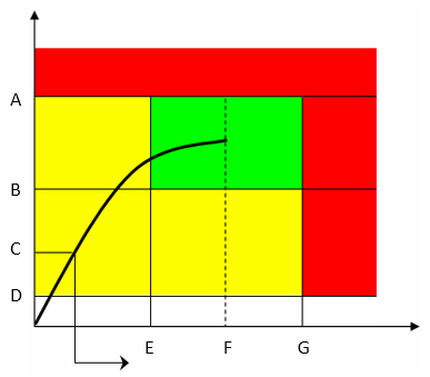
This strategy guides the operator in reaching the desired target torque, without any angle reading.
Parameter | Description |
|---|---|
Required tag number | A specific number must be written in the TAG of the end fitting tool. |
Name | Name of the tightening program. |
Rundown complete torque | Torque value from which the tightening operation starts. |
Torque min | Lower torque limit. |
Torque max | Higher torque limit. |
Change bolt limit | If the torque applied reaches this limit, the message Change screw is shown on the wrench display. |
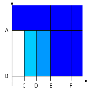
Target torque | The torque target. |
Torque units | Select the unit of measurement. |
Torque correction coefficient | When extensions are used, the wrench measurement might be compensated to show a more accurate torque value. To calculate the correction coefficient, please refer to How to calculate the Torque Correction Coefficient. When extensions are not used, Torque correction coefficient = 1. |
Batch size | Number of tightenings the batch will perform. |
Max consecutive NOK | Number of accepted NOK to have an OK result. |
End cycle time | Starts when the torque goes below the Rundown complete torque after reaching the 3rd percentage. |
Ratchet time | Starts when the torque goes below the Rundown complete torque without reaching the 3rd percentage value. This allows the operator to release the torque for a while and recharge during the tightening operation. |

A | Torque max | B | Target torque |
C | Torque min | D | Rundown complete torque |
The green area indicates the OK result area.
The torque result is the maximum torque measured during the tightening.
During the tightening operation, LEDs, buzzer and vibration are activated as follows:
LEDs:
First radial gradient LEDs (two directions): torque over 1st percentage (30% of the Target torque).
Second radial gradient LEDs (two directions): torque over the 2nd percentage (60% of the Target torque).
Third radial gradient LEDs (two directions): torque over the 3rd percentage (95% of the Target torque).

Torque vs. Angle A
Torque max
B
3rd percentage
C
2nd percentage
D
1st percentage
Buzzer
The beep starts when the torque goes over the Rundown complete torque value; the signal increases when the 1st percentage, the 2nd percentage, the 3rd percentage, and the Torque max are reached.
Vibration:
Starts together with the third radial gradient LEDs.
At the end of the tightening operation, LEDs, buzzer and vibration are activated as follows:
LEDs:
Blue LEDs: torque result between Rundown complete torque and Torque min.
Green LEDs: torque result between Torque min and Torque max.
Red LEDs: torque result over Torque max.
Buzzer
Two beeps indicate the end of the operation; if the final result is in the red area, the signal in continuous.
To stop the buzzer, start a new tightening operation or press a button on the tool controller.
Vibration:
Stays active until the torque applied is released.
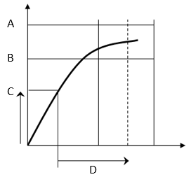
Torque (Control) / Angle (Monitor)
This strategy guides the operator in reaching the desired target torque while monitoring the angle.
Parameter | Description |
|---|---|
Required tag number | A specific number must be written in the TAG of the end fitting tool. |
Name | Name of the tightening program. |
Rundown complete torque | Torque value from which the tightening operation starts. |
Torque min | Lower torque limit. |
Torque max | Higher torque limit. |
Change bolt limit | If the torque applied reaches this limit, the message Change screw is shown on the wrench display. |
Target torque | The torque target. |
Final angle monitoring torque | Torque value from which the angle measurement starts (usually set to 50% of the Target torque). |
Angle min | Lower angle limit. |
Angle max | Higher angle limit. |
Torque units | Select the unit of measurement. |
Angle limit for rehit | If the Torque min value is reached within the specified angle, the message Joint already tightened is shown on the wrench display. |
Measure torque at | Select between Torque peak and Angle peak. |
Torque correction coefficient | When extensions are used, the wrench measurement might be compensated to show a more accurate torque value. To calculate the correction coefficient, please refer to How to calculate the Torque Correction Coefficient. When extensions are not used, Torque correction coefficient = 1. |
Angle correction | When extensions cause additional wrench bending, the wrench angle measurement can be compensated to show a more accurate angle value. When extensions are not used, Angle correction = 0. |
Batch size | Number of tightenings the batch will perform. |
Max consecutive NOK | Number of accepted consecutive NOK to have an OK result. |
End cycle time | Starts when the torque goes below the Rundown complete torque after reaching the 3rd percentage. |
Ratchet time | Starts when the torque goes below the Rundown complete torque without reaching the 3rd percentage value. This allows the operator to release the torque for a while and recharge during the tightening operation. |
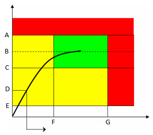
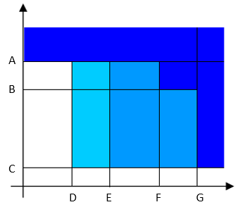
A | Torque max | B | Target torque |
C | Torque min | D | Final angle monitoring torque |
E | Rundown complete torque | F | Angle min |
G | Angle max |
The green area defines the OK result area.
During the tightening operation, LEDs, buzzer and vibration are activated as follows:
LEDs:
First radial gradient LEDs (two directions): torque over the 1st percentage (30% of the Target torque).
Second radial gradient LEDs (two directions): torque over the 2nd percentage (60% of the Target torque).
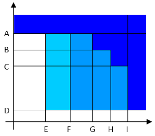
Third radial gradient LEDs (two directions): torque over the 3rd percentage (95% of the Target torque); activated also if torque/angle go over the maximum value.

Torque vs. Angle A
Torque max
B
3rd percentage
C
2nd percentage
D
1st percentage
E
Rundown complete torque
F
Angle max
Buzzer:
Starts when the torque goes over the Rundown complete torque value; the signal increases when the 1st percentage, the 2nd percentage, the 3rd percentage, and the Angle max are reached.
Vibration:
Starts together with the third radial gradient LEDs.
Torque/angle results:
If the torque/angle does not exceed the torque/angle limits, the result is taken at the Torque peak or Angle peak (as specified in the tightening program).
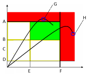
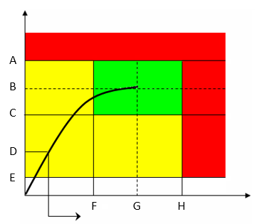
If the torque/angle goes over the limit, the result is taken as follows:

Torque vs. Angle A
Torque max
B
Torque min
C
Final angle monitoring torque
D
Rundown complete torque
E
Angle min
F
Angle max
G
When the Measure torque at is set to Torque peak, and the torque (or both torque and angle) goes over the limits, the result is taken at the torque peak.
H
When the Measure torque at is set to Torque peak , and only the angle goes over the limits, the result is taken at the angle peak.
Torque vs. Angle A
Torque max
B
Torque min
C
Final angle monitoring torque
D
Rundown complete torque
E
Angle min
F
Angle max
G
When the Measure torque at is set to Angle peak, and the angle (or both torque and angle) goes over the limits, the result is taken at the angle peak.
H
When the Measure torque at is set to Angle peak, and only the torque goes over the limits, the result is taken at the torque peak.
At the end of the tightening operation, LEDs, buzzer and vibration are activated as follows:
LEDs:
Blue LEDs: torque result between Rundown complete torque and Torque min, or torque between Torque min and Torque max but angle below the Angle min.
Green LEDs: torque and angle results within the minimum and maximum limits.
Red LEDs: torque result over Torque max, or angle result over Angle max.
Buzzer
Two beeps indicate the end of the operation; if the final result is in the red area, the signal in continuous.
To stop the buzzer, start a new tightening operation or press a button on the tool controller.
Vibration:
Stays active until the torque applied is released.
Torque (Monitor) / Angle (Control)
This strategy guides the operator in reaching the desired target angle while monitoring the torque.
Parameter | Description |
|---|---|
Required tag number | A specific number must be written in the TAG of the end fitting tool. |
Name | Name of the tightening program. |
Rundown complete torque | Torque value from which the tightening operation starts. |
Torque min | Lower torque limit. |
Torque max | Higher torque limit. |
Change bolt limit | If the torque applied reaches this limit, the message Change screw is shown on the wrench display. |
Final angle monitoring torque | Torque value from which the angle measurement starts (usually set to 50% of the Target torque). |
Angle min | Lower angle limit. |
Angle max | Higher angle limit. |
Target angle | The angle target. |
Torque units | Select the unit of measurement. |
Angle limit for rehit | If the Torque min value is reached within the specified angle, the message Joint already tightened is shown on the wrench display. |
Measure torque at | Select between Torque peak and Angle peak. |
Torque correction coefficient | When extensions are used, the wrench measurement might be compensated to show a more accurate torque value. To calculate the correction coefficient, please refer to How to calculate the Torque Correction Coefficient. When extensions are not used, Torque correction coefficient = 1. |
Angle correction | When extensions cause additional wrench bending, the wrench angle measurement can be compensated to show a more accurate angle value. When extensions are not used, Angle correction = 0. |
Batch size | Number of tightenings the batch will perform. |
Max consecutive NOK | Number of accepted consecutive NOK to have an OK result. |
End cycle time | Starts when the torque goes below the Rundown complete torque after reaching the 3rd percentage. |
Ratchet time | Starts when the torque goes below the Rundown complete torque without reaching the 3rd percentage value. This allows the operator to release the torque for a while and recharge during the tightening operation. |
A | Torque max | B | Torque min |
C | Final angle monitoring torque | D | Rundown complete torque |
E | Angle min | F | Target angle |
G | Angle max |
The green area defines the OK result area.
During the tightening operation, LEDs, buzzer and vibration are activated as follows:
LEDs:
First radial gradient LEDs (two directions): angle over the 1st percentage (30% of the Target angle).
Second radial gradient LEDs (two directions): angle over the 2nd percentage (60% of the Target angle).
Third radial gradient LEDs (two directions): angle over the 3rd percentage (95% of the Target angle); activated also if torque/angle go over the maximum value.
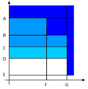
Torque vs. Angle A
Torque max
B
Rundown complete torque
C
1st percentage
D
2nd percentage
E
3rd percentage
F
Angle max
Buzzer:
The beep starts when the torque goes over the Rundown complete torque value; the signal increases when the 1st percentage, the 2nd percentage, the 3rd percentage, and the Torque max are reached.
Vibration:
Starts together with the third radial gradient LEDs.
Torque/angle results:
If the torque/angle does not exceed the torque/angle limits, the result is taken at the Torque peak or Angle peak (as specified in the tightening program).
If the torque/angle goes over the limit, the result is taken as follows:
Torque vs. Angle A
Torque max
B
Torque min
C
Final angle monitoring torque
D
Rundown complete torque
E
Angle min
F
Angle max
G
When the Measure torque at is set to Torque peak, and the torque (or both torque and angle) goes over the limits, the result is taken at the torque peak.
H
When the Measure torque at is set to Torque peak, and only the angle goes over the limits, the result is taken at the angle peak.
Torque vs. Angle A
Torque max
B
Torque min
C
Final angle monitoring torque
D
Rundown complete torque
E
Angle min
F
Angle max
G
When the Measure torque at is set to Angle peak, and the angle (or both torque and angle) goes over the limits, the result is taken at the angle peak.
H
When the Measure torque at is set to Angle peak, and only the torque goes over the limits, the result is taken at the torque peak.
At the end of the tightening operation, LEDs, buzzer and vibration are activated as follows:
LEDs:
Blue LEDs: torque result between Rundown complete torque and Torque min, or torque between Torque min and Torque max but angle below the Angle min.
Green LEDs: angle and torque results within the minimum and maximum limits.
Red LEDs: angle result over Angle max, or torque result over Torque max.
Buzzer
Two beeps indicate the end of the operation; if the final result is in the red area, the signal is continuous.
To stop the buzzer, start a new tightening operation or press a button on the tool controller.
Vibration:
Stays active until the torque applied is released.
Torque + Angle
Using the Torque (Monitor) / Angle (Control) strategy, it is possible to achieve the Torque + Angle strategy.
Define the Final angle monitoring torque value as the torque value from which you want to start performing the “+ Angle” of this strategy:
A | Torque max | B | Torque min |
C | Final angle monitoring torque | D | Target angle |
Torque (Control) / Angle (control) OR
This strategy guides the operator in reaching the desired target torque and angle.
Parameter | Description |
|---|---|
Required tag number | A specific number must be written in the TAG of the end fitting tool. |
Name | Name of the tightening program. |
Rundown complete torque | Torque value from which the tightening operation starts. |
Torque min | Lower torque limit. |
Torque max | Higher torque limit. |
Change bolt limit | If the torque applied reaches this limit, the message Change screw is shown on the wrench display. |
Target torque | The torque target. |
Final angle monitoring torque | Torque value from which the angle measurement starts (usually set to 50% of the Target torque). |
Angle min | Lower angle limit. |
Angle max | Higher angle limit. |
Target angle | The angle target. |
Torque units | Select the unit of measurement. |
Angle limit for rehit | If the Torque min value is reached within the specified angle, the message Joint already tightened is shown on the wrench display. |
Measure torque at | Select between Torque peak and Angle peak. |
Torque correction coefficient | When extensions are used, the wrench measurement might be compensated to show a more accurate torque value. To calculate the correction coefficient, please refer to How to calculate the Torque Correction Coefficient. When extensions are not used, Torque correction coefficient = 1. |
Angle correction | When extensions cause additional wrench bending, the wrench angle measurement can be compensated to show a more accurate angle value. When extensions are not used, Angle correction = 0. |
Batch size | Number of tightenings the batch will perform. |
Max consecutive NOK | Number of accepted consecutive NOK to have an OK result. |
End cycle time | Starts when the torque goes below the Rundown complete torque after reaching the 3rd percentage. |
Ratchet time | Starts when the torque goes below the Rundown complete torque without reaching the 3rd percentage value. This allows the operator to release the torque for a while and recharge during the tightening operation. |
A | Torque max | B | Target torque |
C | Torque min | D | Final angle monitoring torque |
E | Rundown complete torque | F | Angle min |
G | Target angle | H | Angle max |
The green area defines the OK result area.
During the tightening operation, LEDs, buzzer and vibration are activated as follows:
LEDs:
First radial gradient LEDs (two directions): torque over the 1st percentage (30% of the Target Torque - if Torque peak is specified in the tightening program). Angle over the 1st percentage (30% of the Target Angle - if Angle peak is specified in the tightening program).
Second radial gradient LEDs (two directions): torque over the 2nd percentage (60% of the Target Torque - if Torque peak is specified in the tightening program). Angle over the 2nd percentage (60% of the Target Angle - if Angle peak is specified in the tightening program).
Third radial gradient LEDs (two directions): torque and angle are within the minimum and maximum limits; torque or angle have reached the target value; torque or angle go over the maximum value.
Torque peak:
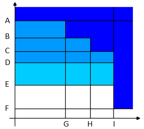
Torque vs. Angle A
Torque max
B
Target torque
C
Torque min
D
2nd percentage
E
1st percentage
F
Rundown complete torque
G
Angle min
H
Target angle
I
Angle max
Angle peak:
Torque vs. Angle A
Torque max
B
Target torque
C
Torque min
D
Rundown complete torque
E
1st percentage
F
2nd percentage
G
Angle min
H
Target angle
I
Angle max
Buzzer:
The beep starts when the torque goes over the Rundown complete torque value; the signal increases when the 1st percentage, the 2nd percentage, torque and angle are within the minimum and maximum limits, and the Torque max or Angle max are reached.
If Angle peak is specified in the tightening program, the buzzer signal monitors the angle instead of the torque.
Vibration:
Starts together with the third radial gradient LEDs.
Torque/angle results:
If torque/angle do not exceed the torque/angle limits, the result is taken at the Torque peak or Angle peak (as specified in the tightening program).
If the torque/angle goes over the limit, the result is taken as follows:
Torque vs. Angle A
Torque max
B
Torque min
C
Final angle monitoring torque
D
Rundown complete torque
E
Angle min
F
Angle max
G
When the Measure torque at is set to Torque peak, and the torque (or both torque and angle) goes over the limits, the result is taken at the torque peak.
H
When the Measure torque at is set to Torque peak, and only the angle goes over the limits, the result is taken at the angle peak.
Torque vs. Angle A
Torque max
B
Torque min
C
Final angle monitoring torque
D
Rundown complete torque
E
Angle min
F
Angle max
G
When the Measure peak at is set to Angle, and the angle (or both torque and angle) goes over the limits, the result is taken at the angle peak.
H
When the Measure peak at is set to Angle, and only the torque goes over the limits, the result is taken at the torque peak.
At the end of the tightening operation, LEDs, buzzer and vibration are activated as follows:
LEDs:
Blue LEDs: angle result between Rundown complete torque and Torque minTorque min, or torque between Torque min and Torque max but angle below the Angle min.
If Angle peak is selected in the tightening program, the Final angle monitoring torque value is used instead of the Rundown complete torque value.Green LEDs: torque and angle results within the minimum and maximum limits.
Red LEDs: torque result over Torque max, or angle result over Angle max.
Buzzer:
Two beeps indicate the end of the operation; if the final result is in the red area, the signal is continuous.
To stop the buzzer, start a new tightening operation or press a button on the tool controller.
Vibration:
Stays active until the torque applied is released.
Torque (Control) / Angle (control) AND
This strategy guides the operator in reaching the desired target torque and angle.
Parameter | Description |
|---|---|
Required tag number | A specific number must be written in the TAG of the end fitting tool. |
Name | Name of the tightening program. |
Rundown complete torque | Torque value from which the tightening operation starts. |
Torque min | Lower torque limit. |
Torque max | Higher torque limit. |
Change bolt limit | If the torque applied reaches this limit, the message Change screw is shown on the wrench display. |
Target torque | The torque target. |
Final angle monitoring torque | Torque value from which the angle measurement starts (usually set to 50% of the Target torque). |
Angle min | Lower angle limit. |
Angle max | Higher angle limit. |
Target angle | The angle target. |
Torque units | Select the unit of measurement. |
Angle limit for rehit | If the Torque min value is reached within the specified angle, the message Joint already tightened is shown on the wrench display. |
Measure torque at | Select between Torque peak and Angle peak. |
Torque correction coefficient | When extensions are used, the wrench measurement might be compensated to show a more accurate torque value. To calculate the correction coefficient, please refer to How to calculate the Torque Correction Coefficient. When extensions are not used, Torque correction coefficient = 1. |
Angle correction | When extensions cause additional wrench bending, the wrench angle measurement can be compensated to show a more accurate angle value. When extensions are not used, Angle correction = 0. |
Batch size | Number of tightenings the batch will perform. |
Max consecutive NOK | Number of accepted consecutive NOK to have an OK result. |
End cycle time | Starts when the torque goes below the Rundown complete torque after reaching the 3rd percentage. |
Ratchet time | Starts when the torque goes below the Rundown complete torque without reaching the 3rd percentage value. This allows the operator to release the torque for a while and recharge during the tightening operation. |
A | Torque max | B | Target torque |
C | Torque min | D | Final angle monitoring torque |
E | Rundown complete torque | F | Angle min |
G | Target angle | H | Angle max |
The green area defines the OK result area.
During the tightening operation, LEDs, buzzer and vibration are activated as follows:
LEDs:
First radial gradient LEDs (two directions): torque over the 1st percentage (30% of the Target Torque - if Torque Peak is specified in the tightening program). Angle over the 1st percentage (30% of the Target Angle - if Angle Peak is specified in the tightening program).
Second radial gradient LEDs (two directions): torque over the 2nd percentage (60% of the Target Torque - if Torque Peak is specified in the tightening program). Angle over the 2nd percentage (60% of the Target Angle - if Angle Peak is specified in the tightening program).
Third radial gradient LEDs (two directions): torque and angle are within the minimum and maximum limits; torque or angle have reached the target value; torque or angle go over the maximum value.
Torque Peak:
Torque vs. Angle A
Torque max
B
Target torque
C
2nd percentage
D
1st percentage
E
Rundown complete torque
F
Target angle
G
Angle max
Angle Peak:
Torque vs. Angle A
Torque max
B
Target torque
C
Rundown complete torque
D
1st percentage
E
2nd percentage
F
Target angle
G
Angle max
Buzzer:
The beep starts when the torque goes over the Rundown complete torque value; the signal increases when the 1st percentage, the 2nd percentage, the angle and target values, and the Torque max are reached.
If Angle peak is specified in the tightening program, the buzzer signal monitors the angle instead of the torque.
Vibration:
Starts together with the third radial gradient LEDs.
Torque/angle results:
If the torque/angle does not exceed the torque/angle limits, the result is taken at the Torque Peak or Angle Peak (as specified in the tightening program).
If the torque/angle goes over the limit, the result is taken as follows:
Torque vs. Angle A
Torque max
B
Torque min
C
Final angle monitoring torque
D
Rundown complete torque
E
Angle min
F
Angle max
G
When the Measure peak at is set to Torque peak, and the torque (or both torque and angle) goes over the limits, the result is taken at the torque peak.
H
When the Measure peak at is set to Torque peak, and only the angle goes over the limits, the result is taken at the angle peak.
Torque vs. Angle A
Torque max
B
Torque min
C
Final angle monitoring torque
D
Rundown complete torque
E
Angle min
F
Angle max
G
When the Measure torque at is set to Angle peak, and the angle (or both torque and angle) goes over the limits, the result is taken at the angle peak.
H
When the Measure torque at is set to Angle peak, and only the torque goes over the limits, the result is taken at the torque peak.
At the end of the tightening operation, LEDs, buzzer and vibration are activated as follows:
LEDs:
Blue LEDs: angle result between Rundown complete torque and Torque min, or torque between Torque min and Torque max with angle below the Angle min.
If Angle peak is selected in the tightening program, the Final angle monitoring torque value is used instead of the Rundown complete torque value.Green LEDs: torque and angle results within the minimum and maximum limits.
Red LEDs: torque result over Torque max, or angle result over Angle max.
Buzzer:
Two beeps indicate the end of the operation; if the final result is in the red area, the signal is continuous.
To stop the buzzer, start a new tightening operation or press a button on the tool controller.
Vibration:
Stays active until the torque applied is released.
Loose
Parameter | Description |
|---|---|
Required tag number | A specific number must be written in the TAG of the end fitting tool. |
Name | Name of the tightening program. |
Rundown complete torque | Torque value from which the tightening operation starts. |
Torque min | Lower torque limit. |
Torque max | Higher torque limit. |
Change bolt limit | If the torque applied reaches this limit, the message Change screw is shown on the wrench display. |
Target angle | The angle target. |
Torque units | Select the unit of measurement. |
Torque correction coefficient | When extensions are used, the wrench measurement might be compensated to show a more accurate torque value. To calculate the correction coefficient, please refer to How to calculate the Torque Correction Coefficient. When extensions are not used, Torque correction coefficient = 1. |
Angle correction | When extensions cause additional wrench bending, the wrench angle measurement can be compensated to show a more accurate angle value. When extensions are not used, Angle correction = 0. |
Batch size | Number of tightenings the batch will perform. |
End cycle time | Starts when the torque goes below the Rundown complete torque after reaching the Target angle. |
Ratchet time | Starts when the torque goes below the Rundown complete torque without reaching the Target angle value. |
This strategy is used to loosen a tightened screw. This is typically used in the sequence of a Multistep program.
For example:
Tighten the screw to 40 Nm
Loosen the screw by 30°
Tighten the screw to 50 Nm
The torque result is measured at the specified Target angle value.
If the Target angle is left at zero, this strategy automatically looks for torque / angle values to detect if the loosening process has been completed.
If a Target angle value is specified, loosening must reach the Target angle value in order to consider the result as OK.
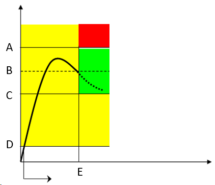
A | Torque max | B | Target torque |
C | Torque min | D | Rundown complete torque |
E | Target angle |
The green area defines the OK result area.
During the tightening operation, LEDs, buzzer and vibration are activated as follows:
LED:
White LED: activated when the Rundown complete torque is reached.
Buzzer:
The beep starts when the torque goes over the Rundown complete torque value; the signal increases when the Target angle is reached / the loosening process has been completed.
Vibration:
Starts when the Target angle is reached.
At the end of the tightening operation, LEDs, buzzer and vibration are activated as follows:
LEDs:
Green LEDs: torque result within the minimum and maximum limits.
Red LEDs: torque result over the Torque max.
Buzzer
Two beeps indicate the end of the operation; if the final result is in the red area, the signal in continuous.
To stop the buzzer, start a new tightening operation or press a button on the tool controller.
Vibration:
Stays active until the torque applied is released.
Correction Coefficients for Extensions
When the joint design or space limitations preclude the use of standard sockets or tools, it may be necessary to use special extension spanners to fit the application. In these cases, the STRwrench measurement can be adequately compensated since the factory calibration is made for the standard arm, and the extension arm increases the torque measured proportionally to its length. The angle measured could also be affected by the extensions, due to its specific torsion when torque is applied.
When a torque multiplier is used on the STRwrench, the torque applied on the joint is greater than the torque produced by the wrench; in this case the torque correction coefficient is used to adjust the wrench torque reading. The angle measurement is also affected, but the wrench cannot compensate the angle measurement.
How to calculate the Torque Correction Coefficient

D | Torque value displayed | T | Torque applied |
L | Standard arm (from the center of the handle to the center of the end fitting tool) | L+E | Total arm |
E | Extension arm |
From the relation between the displayed and applied torque 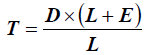 , the Torque correction coefficient is given by the following formula:
Torque correction coefficient = 
The Torque correction coefficient alters the wrench torque measurement; a wrong value for this coefficient may cause an improper torque reading, and the risk of doing a tightening at a target torque different from the one expected. Ensure you have calculated the proper value when an extension is used.
For end fitting tools used without wrench extensions, the Torque correction coefficient must be left set to 1.
When using an extension, the handling position affects the torque reading. Always position the hand on the center of the STRwrench handle.
If a torque multiplier is used on the STRwrench, the Torque Correction Coefficient must be set equal to the torque multiplying coefficient of the torque multiplier.
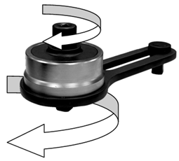
The Torque correction coefficient is given by the following formula:
Torque correction coefficient = Torqueoutput / Torqueinput
How to Calculate the Angle Correction
When a wrench extension is used, the Angle Correction allows linear compensation of the extension torsion based on the torque applied. The correction value is expressed in degrees at the smartHEAD Max torque.
On the Power Focus, configure a Torque (Control) / Angle (Monitor) tightening program with the following values:
Rundown complete torque = smartHEAD Min torque value (5% of smartHEAD Max torque)
Final angle monitoring torque = Rundown complete torque
Target torque = 75% of smartHEAD Max torque
Do three tightenings at 75% of the smartHEAD Max torque.
For each torque and angle value measured, do the following calculation:
Angle correction = Angle measured x (smartHEAD Max torque - smartHEAD Min torque) / (Torque measured - smartHEAD Min torque)
Make sure the minimum and maximum angle values calculated do not differ by more than 10% of the maximum value calculated:
Angle correctionmax - Angle correctionmin ≤ Angle correctionmax / 10
If they differ by more than 10%, repeat the procedure from the beginning.
Average the three angle values calculated to obtain the Angle correction.
When a torque multiplier is used on the STRwrench, the Angle correction value must be left to zero; in this case the STRwrench cannot compensate the angle measurement.
List of Third-Party Licenses
STRwrench controllers incorporate third-party components whose licenses require us to publish copies of the licensing language and/or copyright notices. In compliance with those requirements, here are copies of the licenses. Please, click on any of the licenses below to show a copy of the license text.
Software | Version | Licenses |
|---|---|---|
acl | 2.2.52 | |
alsa-lib | 1.1.2 | |
alsa-state | 0.2.0 | |
alsa-tools | 1.1.0 | |
alsa-utils | 1.1.2 | |
anybus | 1.1 |
|
atftp | 0.7.1 + gitAUTOINC + be3291a18c | |
attr | 2.4.47 | |
barebox | 2018.06.0 | |
base-files | 3.0.14 | |
base-files-px2-base | 1.0 | |
base-passwd | 3.5.29 | |
bash | 4.3.30 | |
bash-completion | 2.4 | |
bluez5 | 5.41 | |
boost | 1.61.0 | |
busybox-px2base | 1.24.1 | |
bzip2 | 1.0.6 | |
ca-certificates | 20160104 | |
cppunit | 1.13.1 | |
cryptodev-linux | 1.8 | |
curl | 7.50.1 | |
db | 3.0.35 | |
dbus | 1.10.10 | |
dhcp | 4.3.4 | |
dosfstools | 4.0 | |
dt-utils | 2017.03.0 | |
e2fsprogs | 1.43 | |
ecryptfs-tools | 1.0 | |
elfutils | 0.166 | |
eudev | 3.2.2 | |
expat | 2.2.0 | |
fbset | 2.1 | |
fb-test | 1.1.0 | |
fcgi | 2.4.0 | |
finit | 3.1 | |
firmware-imx | 5.4 |
|
flac | 1.3.1 | |
flatbuffers | 1.9.0 | |
fruit | 3.4.0 + gitAUTOINC + ece0f7218c | |
fuse | 2.9.4 | |
gcc-runtime | 6.2.0 | |
gdb | 8.0.1 | |
gdbm | 1.12 | |
glib-2.0 | 2.48.2 | |
glibc | 2.24 | |
gmp | 6.1.1 | |
gnutls | 3.5.3 | |
grep | 2.25 | |
gstreamer1.0 | 1.8.3 | |
gstreamer1.0-plugins-base | 1.8.3 | |
hostpad | 2.6 | |
htop | 1.0.3 | |
icu | 57.1 | |
init-ifupdown | 1.0 | |
initscripts | 1.0 | |
iproute2 | 4.7.0 | |
iptables | 1.6.0 | |
ipwatchd | 1.2 | |
iw | 4.7 | |
json-spirit | 4.08 | |
keyutils | 1.5.9 | |
kmod | 23 + gitAUTOINC + 65a885df5f | |
kmsfbwrap-px2base | 12.0 | |
libarchive | 3.2.2 | |
libbsd | 0.8.3 |
|
libcap | 2.25 | |
libdrm | 2.4.70 | |
libestr | 0.1.10 | |
libevent | 2.0.22 | |
libfastjson | 0.99.4 | |
libffi | 3.2.1 | |
libgcc | 6.2.0 | |
libgcrypt | 1.7.3 | |
libgpg-error | 1.24 | |
libidn | 1.33 | |
libite | 2.0.2 | |
libjpeg-turbo | 1.5.0 | |
liblogging | 1.0.5 | |
libnet | 1.2-rc3 | |
libnfsidmap | 0.25 | |
libnl | 3.2.28 | |
libogg | 1.3.2 | |
libpcap | 1.8.1 | |
libpcre | 8.39 | |
libpng | 1.6.24 | |
librcf | 2.2.0.0 | |
libsamplerate0 | 0.1.8 | |
libsndfile1 | 1.0.27 | |
libtinyxml | 2.6.2 | |
libtirpc | 1.0.1 | |
libuev | 2.2.0 | |
libusb1 | 1.0.20 | |
libvorbis | 1.3.5 | |
libxml2 | 2.9.4 | |
libxslt | 1.1.29 | |
lighttpd | 1.4.51 | |
linux-atlas | 4.14 | |
linux-libc-headers | 4.14.13 | |
logrotate | 3.9.1 | |
lua | 5.1.5 | |
luabind | git | |
lzo | 2.09 | |
lzop | 1.03 | |
memlog | 2.0 | |
mesa | 12.0.1 | |
mg | 20161005 |
|
minizip | 1.2.8 | |
mmc-utils | 0.1 | |
mtd-utils | 1.5.2 | |
nano | 2.2.5 | |
ncurses | 6.0 + 20160625 | |
netbase | 5.3 | |
netcat-openbsd | 1.105 | |
nettle | 3.2 | |
nfs-utils | 2.1.1 | |
ntp | 4.2.8p8 | |
openssh | 7.6p1 | |
openssl | 1.0.2n | |
opkg | 0.3.3 | |
opkg-arch-config | 1.0 | |
opkg-utils | 0.3.2 + gitAUTOINC + 3ffece9bf1 | |
orc | 0.4.25 | |
os-release | 1.0 | |
packagegroup-atlas-qt5 | 1.0 | |
packagegroup-atlas-sxb | 1.0 | |
packagegroup-base | 1.0 | |
packagegroup-core-boot | 1.0 | |
packagegroup-core-eclipse-debug | 1.0 | |
packagegroup-core-nfs | 1.0 | |
packagegroup-core-ssh-openssh | 1.0 | |
packagegroup-px2it | 1.0 | |
parted | 3.2 | |
perl | 5.22.1 | |
pm-utils | 1.4.1 | |
poco | 1.9.0 | |
pointercal | 0.0 | |
popt | 1.16 | |
procps | 3.3.12 | |
protobuf | 2.6.1 + gitAUTOINC + bba83652e1 | |
python | 2.7.12 | |
qtbase | 5.7.1 + gitAUTOINC + a55f36211e | |
qtdeclarative | 5.7.1 + gitAUTOINC + 2a992040e2 | |
qtlocation | 5.7.1 + gitAUTOINC + de5be121d8 | |
qtsensors | 5.7.1 + gitAUTOINC + 5a57beaaa5 | |
qtwebkit | 5.7.1 + gitAUTOINC + 76e2732f01 | |
qtwebsockets | 5.7.1 + gitAUTOINC + 60cede232a | |
qtxmlpatterns | 5.7.1 + gitAUTOINC + 89dbcc4f80 | |
rauc | 0.4 | |
readline | 6.3 | |
rpcbind | 0.2.3 | |
rsync | 3.1.2 | |
rsyslog | 8.22.0 | |
run-postinsts | 1.0 | |
shadow | 4.2.1 | |
shadow-security | 4.2.1 | |
sqlite3 | 3.14.1 |
|
squashfs-tools | 5.7.1 + gitrAUTOINC + 9c1db6d13a |
|
st-load | 1.0 |
|
stm32flash | git | |
strace | 4.13 | |
sysfsutils | 2.1.0 | |
sysvinit-bootlogd | 2.88dsf | |
tcf-agent | 1.4.0 + gitAUTOINC + 2dddd5f440 | |
tcpdump | 4.7.4 | |
tcp-wrappers | 7.6 | |
tslib | 1.1 | |
tzdata | 2016i |
|
u-boot-atlas | 2017.09 | |
u-boot-fw-utils | 2017.09 | |
unzip | 6.0 | |
usbutils | 008 | |
util-linux | 2.28.1 | |
wireless-tools | 30.pre9 | |
wpa-supplicant | 2.5 | |
xerces-c | 2.7.0 | |
xz | 5.2.2 |
|
yaml-cpp | 0.6.2 | |
zip | 3.0 | |
zlib | 1.2.8 |