MTRwrench CRADLE
Product Information
General Information
Safety Signal Words
The safety signal words Danger, Warning, Caution, and Notice have the following meanings:
DANGER | DANGER indicates a hazardous situation which, if not avoided, will result in death or serious injury. |
WARNING | WARNING indicates a hazardous situation which, if not avoided, could result in death or serious injury. |
CAUTION | CAUTION, used with the safety alert symbol, indicates a hazardous situation which, if not avoided, could result in minor or moderate injury. |
NOTICE | NOTICE is used to address practices not related to personal injury. |
Warranty
Product warranty will expire in 12+1 months after dispatch from Atlas Copco's Distribution Center.
Normal wear and tear on parts is not included within the warranty.
Normal wear and tear is that which requires a part change or other adjustment/overhaul during standard tool maintenance typical for that period (expressed in time, operation hours or otherwise).
The product warranty relies on the correct use, maintenance, and repair of the tool and its component parts.
Damage to parts that occurs as a result of inadequate maintenance or performed by parties other than Atlas Copco or their Certified Service Partners during the warranty period is not covered by the warranty.
To avoid damage or destruction of tool parts, service the tool according to the recommended maintenance schedules and follow the correct instructions.
Warranty repairs are performed only in Atlas Copco workshops or by Certified Service Partners.
Atlas Copco offers extended warranty and state-of-the-art preventive maintenance through its ToolCover contracts. For further information, contact your local Service representative.
For electrical motors:
Warranty will apply, only when the electric motor has not been opened.
Website
Information concerning our Products, Accessories, Spare Parts and Published Matters can be found on the Atlas Copco website.
Please visit: www.atlascopco.com.
ServAid
ServAid is a portal that is continuously updated and contains Technical Information, such as:
Regulatory and Safety Information
Technical Data
Installation, Operation and Service Instructions
Spare Parts Lists
Accessories
Dimensional Drawings
Please visit: https://servaid.atlascopco.com.
For further Technical Information, please contact your local Atlas Copco representative.
Safety Data Sheets MSDS/SDS
The Safety Data Sheets describe the chemical products sold by Atlas Copco.
Please consult the Atlas Copco website for more information www.atlascopco.com/sds.
Country of Origin
For the Country of Origin, please refer to the information on the product label.
Dimensional Drawings
Dimensional Drawings can be found either in the Dimensional Drawings Archive, or on ServAid.
Please visit: http://webbox.atlascopco.com/webbox/dimdrw or https://servaid.atlascopco.com.
Overview
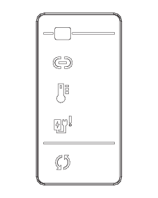
Charger Functionality
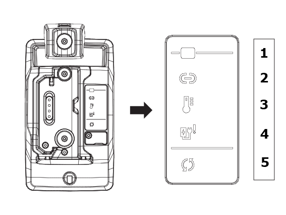
Position | Description |
|---|---|
1 | Battery ON |
2 | Connectivity via CAN-bus |
3 | Temperature warning |
4 | Hardware error |
5 | Charging process |
Environmental Conditions
Indoor use only | |
Altitude | Up to 2000 m |
Ambient temperature range | +5 to +40 °C |
Maximum relative humidity 80 % for temperatures up to 31 °C decreasing linearly to 50 % relative humidity at 40 °C |
|
Product Data
Input power | 24 V — 3.5 W (max) |
Output power | 2.1 V — 1.2 A (max) |
Operating temperature | +5 to + 40 °C |
Charging time | 180 minutes (max) with recommended battery (P/N 4027004820) |
Power supply | 24 VCC |
Dimensions
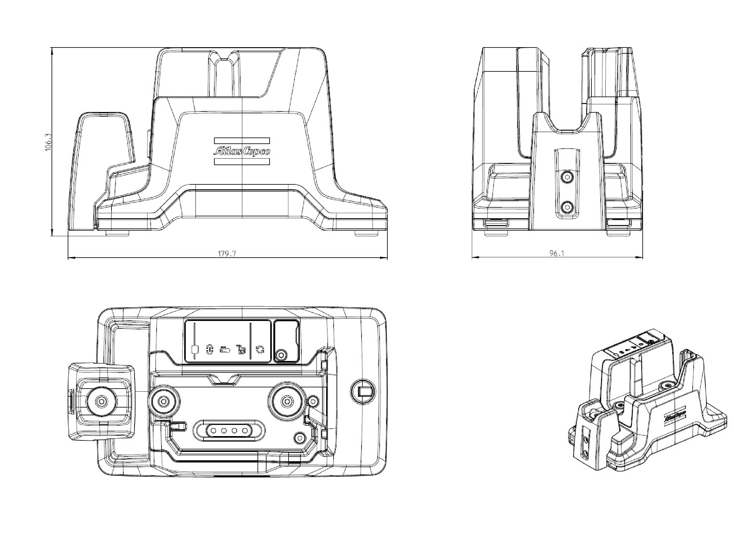
Dimensions in mm
Technical Product Data
Technical Product Data can be found on either ServAid, or the Atlas Copco website.
Please visit: https://servaid.atlascopco.com or www.atlascopco.com.
Use
Mains voltage 24 V cc.
Charging time is max 3 hours, based on an ambient temperature of 25°C.
No other use permitted. For professional use only.
Installation
Installation Instructions
Assembling the frontal support
The MTRwrench cradle is delivered with cradle support for 85/200 Nm (4027004805) included in the box.
The MTRwrench cradle required support to hold the MTRwrench in the correct position during charging.
|
|
|
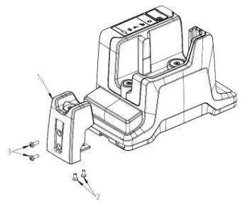
Remove the screws (2) and the support (1).

The support is not to be used for wrenches of 25 Nm and 50 Nm capacity.
The support must be used with wrenches of 85 Nm and 200 Nm capacity.
Install the support (1) with the screws (2).
Loosen the screws (3) to adjust the position of the support (1).
Adjust the position so that the support (1) is in contact with wrench tube.
Tighten the screws (3) and the support (1).
Installing the charger
The MTRwrench cradle can be installed both horizontally and vertically, on a tabletop or in a cabinet.
|
|
|
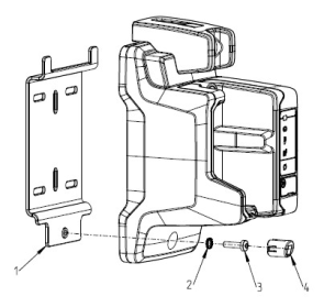
Slide the horns of the mounting plate (1) into the corresponding holes in the bottom of the MTRwrench cradle.
The vertical mounting plate (1) has slotted holes for mounting onto walls, tabletops or cabinets.
Make sure the mounting is stable and secure.
Remove the screw cover (4).
Install the washer (2) and the screw (3) into the hole and tighten at a torque of 1.5 Nm.
Install the screw cover (4).
Operation
Ergonomic Guidelines
Consider your workstation as you read through this list of general ergonomic guidelines to identify areas for improvement in posture, component placement, or work environment.
Take frequent breaks and change work positions frequently.
Adapt the workstation area to your needs and the work task.
Adjust for a convenient reach range by determining where parts and tools need to be located to avoid static load.
Use workstation equipment such as tables and chairs appropriate for the work task.
Avoid work positions above shoulder level or with static holding during assembly operations.
When working above shoulder level, reduce the load on the static muscles by lowering the weight of the tool, using for example torque arms, hose reels or weight balancers. You can also reduce the load on the static muscles by holding the tool close to the body.
Take frequent breaks.
Avoid extreme arm or wrist postures, particularly during operations requiring a degree of force.
Adjust for a convenient field of vision that requires minimal eye and head movements.
Use appropriate lighting for the work task.
Select the appropriate tool for the work task.
In noisy environments, use ear protection equipment.
Use high-quality inserted tools and consumables to minimize exposure to excessive levels of vibration.
Minimize exposure to reaction forces.
When cutting:
A cut-off wheel can get stuck if the cut-off wheel is bent or not guided properly. Always use the correct flange for the cut-off wheel and avoid bending the cut-off wheel during operation.
When drilling:
The drill might stall when the drill bit breaks through. Use support handles if the stall torque is high. The safety standard ISO11148 part 3 recommends using a device to absorb a reaction torque above 10 Nm for pistol grip tools and 4 Nm for straight tools.
When using direct-driven screwdrivers or nutrunners:
Reaction forces depend on the tool settings and joint characteristics. Strength and posture determine the amount of reaction force that an operator can tolerate. Adapt the torque setting to the operator's strength and posture and use a torque arm or reaction bar if the torque is too high.
In dusty environments, use a dust extraction system or wear a mouth protection mask.
Operating Instructions
Operating the charger
The MTRwrench cradle is designed to be supplied by the external power supply P/N 4027004802 or by the Power Bank Adaptor P/N 8439004832z.
Connect the charger to the main power supply or power bank adaptor. When the charger is connected to the mains supply, the power indicator glows green.
Interconnect chargers
The cradle can be used in interconnection using CAN-bus daisy chain. The maximum number of cradles interconnected is limited as follow:
Up to 8 using external power supply P/N 4027004802.
Up to 8 using the Power Bank Adaptor P/N 8439004832 with brand new fully charged Atlas Copco battery 36 V P/N 4211613014.
Up to 4 using the Power Bank Adaptor P/N 8439004832 with brand new fully charged Atlas Copco battery 18 V P/N 4211613006.
Up to 3 using the Power Bank Adaptor P/N 8439004832 with brand new fully charged Atlas Copco battery 14 V P/N 4211613002.
Cradle display
Behavior | Color | Description |
|---|---|---|
| Steady white | Power ON |
| Blinking Blue | Connection established Data communication via CAN-bus enabled |
| Blinking Red | High temperature. Power supply is shut off and will resume automatically when the temperature comes back to normal |
| Steady Red | Hardware error. Internal diagnostics process has failed |
| Steady white Blinking white Steady Green Blinking Red | Charging Battery check Charging completed Charging Error/Wrong battery used on wrench |


Service
Service Recommendations
Preventive maintenance is recommended at regular intervals. See the detailed information on preventive maintenance. If the product is not working properly, take it out of service and inspect it.
If no detailed information about preventive maintenance is included, follow these general guidelines:
Clean appropriate parts accurately
Replace any defective or worn parts
Maintenance Instructions
General Service and Maintenance Safety
Do not open the charger. Repairs are only to be performed by authorised service technicians.
Troubleshooting
Cradle Error
Charger Errors
Indicator | Light behavior | Description |
|---|---|---|
| Blinking | High temperature. Power supply is shut off and will resume automatically when the temperature comes back to normal. |
| Steady | Hardware error: Internal diagnostics failed. Possible problem on the electronic board |
| Blinking red | Charging error/wrong battery used on wrench. |

Recycling
Environmental Regulations
When a product has served its purpose it has to be recycled properly. Dismantle the product and recycle the components in accordance with local legislation.
Batteries shall be taken care of by your national battery recovery organization.
Recycling Instructions
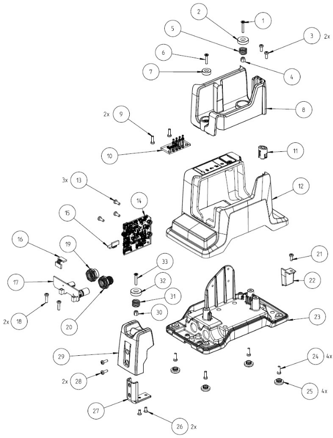
Position | Part | Recycle as |
|---|---|---|
1 | Screw | Stainless steel |
2 | Magnet | WEEE |
3 | Screw | Steel |
4 | Nut | Stainless steel |
5 | Spring | Steel |
6 | Screw | Stainless steel |
7 | Magnet | WEEE |
8 | Wrench holder | Mixed waste |
9 | Screw | Steel |
10 | Electronic board | WEEE |
11 | Cover | Polyamide |
12 | Top cover | Mixed waste |
13 | Screw | Steel |
14 | Electronic board | WEEE |
15 | Cable | WEEE |
16 | Cable | WEEE |
17 | Electronic board | WEEE |
18 | Screw | Steel |
19 | Connector | Steel |
20 | Connector | Steel |
21 | Screw | Steel |
22 | Cover | Polyamide |
23 | Base | Aluminum |
24 | Screw | Steel |
25 | Foot | Rubber |
26 | Screw | Steel |
27 | Plate | Steel |
28 | Screw | Steel |
29 | Support | Mixed waste |
30 | Nut | Stainless steel |
31 | Spring | Steel |
32 | Magnet | WEEE |
33 | Screw | Stainless steel |