GFA-HIT
Geared Front Attachment
Product Information
General Information

Safety Signal Words
The safety signal words Danger, Warning, Caution, and Notice have the following meanings:
DANGER | DANGER indicates a hazardous situation which, if not avoided, will result in death or serious injury. |
WARNING | WARNING indicates a hazardous situation which, if not avoided, could result in death or serious injury. |
CAUTION | CAUTION, used with the safety alert symbol, indicates a hazardous situation which, if not avoided, could result in minor or moderate injury. |
NOTICE | NOTICE is used to address practices not related to personal injury. |
Warranty
Product warranty will expire in 12+1 months after dispatch from Distribution Center.
Normal wear and tear on parts is not included within the warranty.
Normal wear and tear is that which requires a part change or other adjustment/overhaul during standard tool maintenance typical for that period (expressed in time, operation hours or otherwise).
The product warranty relies on the correct use, maintenance, and repair of the tool and its component parts.
Damage to parts that occurs as a result of inadequate maintenance or performed by parties other than the manufacturer or their Certified Service Partners during the warranty period is not covered by the warranty.
To avoid damage or destruction of tool parts, service the tool according to the recommended maintenance schedules and follow the correct instructions.
Warranty repairs are performed only in authorized workshops or by Certified Service Partners.
Extended warranty and state-of-the-art preventive maintenance services are available through the designated service contacts. For further information, contact your local service representative.
Country of Origin
For the Country of Origin, please refer to the information on the product label.
Overview
System Description
The Inline Gear Front Attachment (GFA) system is used for Hold and Drive (HAD) tightening and loosening of screws. that is, a system that holds the screw so that it does not spin while tightening a nut on the screw. The system can be used for screw connections in locations that are difficult to access.
The tightening operation is controlled by a separate drive unit to which the system is fitted. The drive unit can be of either pneumatic or electric type.
The modular structure of the system allows for a wide range of configurations available for different screw connections and tightening processes.
System Components
The modular GFA system is made up of the following main components:

Position | Component | Function |
|---|---|---|
A | Adapter | With an adapter the GFA system can be fitted to different interfaces. The interface varies depending on the drive unit model. |
B | Gear Front Attachment (GFA) module | The GFA module comprises a housing which contains a number of gears in order to keep the central axis fixed. |
C | Hold and Drive | With a hold and drive socket the screw is kept fixed with a bit, while the nut is being tightened. |
GFA performance
For maximum recommended torque see SI.
Accuracy 3σ: 6%.
Never exceed the recommended maximum torque.
The estimated product life of the HIT is 250,000 tightenings.

The socket will be subject to wear and is therefore considered as a consumable product.
Installation
Installation Instructions
Assembling the GFA Module
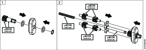

Dismantling the GFA Module


Assembling the GFA System on the Pistol Tool
Preparations
If the ring and locking parts are assembled on the tool, please follow the actions below.
Hold the drive unit in position with a C-spanner securing the gear housing of the tool. Loosen and remove the ring with another C-spanner, in the clockwise direction.
Unlock and remove the locking parts from the drive unit with a small screwdriver.
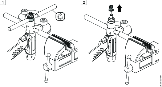
Assembling the GFA module on the Pistol Tool
Hold the drive unit in position with a C-spanner securing the gear housing of the tool. Clean the threads of the drive unit and the threads of the bottom part of the adapter.
Apply Loctite 2701, or similar, to the threads of the drive unit.
Tighten the adapter with a C-spanner, in the counterclockwise direction, to 30 Nm.
Hold the adapter in position with a C-spanner. Clean the threads of the top part of the adapter, and the threads of the cap nut of the GFA module.
Apply Loctite 243, or similar, to the threads of the top part of the adapter.
Tighten the cap nut of the GFA module with a C-spanner, in the clockwise direction, to 10 Nm.
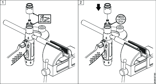


Dismantling the GFA System on the Pistol Tool
Hold the adapter of the GFA system in position with a C-spanner. Loosen the cap nut of the GFA module with another C-spanner, in the counterclockwise direction.
Remove the GFA module from the adapter.
Hold the drive unit in position with a C-spanner securing the gear housing of the tool. Loosen the adapter with another C-spanner, in the clockwise direction.
Remove the adapter from the drive unit.


Assembling XB-P Adapter Instructions
Preparation
For the HIT assembly, remove the existing bit holder and the nose nut from the XB-P tool.

Attaching a XB-P Adapter
Fit the rotation locking ring to the XB-P housing. Slide the four internal fins into the corresponding grooves in the housing.

Tighten the nose nut to the XB-P housing using the following procedure:
Tighten to 20 Nm (counterclockwise) using a pin spanner.
Use the assembly tool 4080 1471 80 to tighten the nose nut.
Wait a minimum of 10 minutes (without loosening the initial applied torque).
Retighten to 20 Nm (counterclockwise) using a pin spanner.
The two-step tightening process is important because the plastic housing may relax after the first tightening.
When tightening, secure the rotation locking ring with a C-spanner.

Tighten the adapter part to the rotation locking ring:
Apply Loctite 243 to the threads.
Tighten to 20 Nm in a counterclockwise direction.
When tightening, secure the rotation locking ring with a C-spanner.

Engage the splines between the adapter part and the HIT. Ensure that the shaft connects properly. Then tighten using the following procedure:
Apply Loctite 243 to the threads.
Tighten to 10 Nm in a clockwise direction.
When tightening, secure the adapter part with a C-spanner.

Removing a XB-P Adapter
To remove the adapter from the XB-P tool, follow the assembly steps in reverse order.
For HIT assembly and disassembly, the bit holder is not required.
Functional Test
The functional test is done on the GFA module disconnected from the tool.
Perform a functional test before the first tightening operation, and after any performed maintenance activities.
Turn the output gear wheel by hand. It should be turned easily.

If it is hard to turn, open the housing and check that all components are in the correct position. If issues persist, contact Atlas Copco Customer Center.
Lubricate the system and assemble.
Operation
Ergonomic Guidelines
Consider your workstation as you read through this list of general ergonomic guidelines to identify areas for improvement in posture, component placement, or work environment.
Take frequent breaks and change work positions frequently.
Adapt the workstation area to your needs and the work task.
Adjust for a convenient reach range by determining where parts and tools need to be located to avoid static load.
Use workstation equipment such as tables and chairs appropriate for the work task.
Avoid work positions above shoulder level or with static holding during assembly operations.
When working above shoulder level, reduce the load on the static muscles by lowering the weight of the tool, using for example torque arms, hose reels or weight balancers. You can also reduce the load on the static muscles by holding the tool close to the body.
Take frequent breaks.
Avoid extreme arm or wrist postures, particularly during operations requiring a degree of force.
Adjust for a convenient field of vision that requires minimal eye and head movements.
Use appropriate lighting for the work task.
Select the appropriate tool for the work task.
In noisy environments, use ear protection equipment.
Use high-quality inserted tools and consumables to minimize exposure to excessive levels of vibration.
Minimize exposure to reaction forces.
When cutting:
A cut-off wheel can get stuck if the cut-off wheel is bent or not guided properly. Use the correct flange for the cut-off wheel and avoid bending the cut-off wheel during operation.
When drilling:
The drill might stall when the drill bit breaks through. Use support handles if the stall torque is high. The safety standard ISO11148 part 3 recommends using a device to absorb a reaction torque above 10 Nm for pistol grip tools and 4 Nm for straight tools.
When using direct-driven screwdrivers or nutrunners:
Reaction forces depend on the tool settings and joint characteristics. Strength and posture determine the amount of reaction force that an operator can tolerate. Adapt the torque setting to the operator's strength and posture and use a torque arm or reaction bar if the torque is too high.
In dusty environments, use a dust extraction system or wear a mouth protection mask.
Operating Instructions
Operating the GFA System
Service
Service Overview
The HIT system is designed to last without need for maintenance of internal parts or greasing.
Service Instructions and Intervals
Daily service
Clean the exterior of the GFA.
Inspect the GFA for any damage.
Check all fastenings of the GFA.
Run functional tests and listen for any abnormal noise.
Maintenance Instructions
Changing a HAD socket bit
Remove the two T8 screws.
Remove the socket from the inline front part.
Remove the bit from the bit holder.


Place the bit in the bit holder and secure it with a set screw.
Place the socket on the inline front part.
Tighten the two T8 screws. Make sure that the screws enter the holes on the output shaft of the inline front part.


Cleaning the System
To clean the system, wipe carefully with a clean, smooth cloth.
Recycling
Environmental Regulations
When a product has served its purpose it has to be recycled properly. Dismantle the product and recycle the components in accordance with local legislation.
Batteries shall be taken care of by your national battery recovery organization.
Recycling Information
Recycle the GFA as steel. Recycle scratch covers as TPU.

Part | Recycle as |
1-5, 7, 9-11 | Steel |
6, 8 | Aluminium |