Tensioning procedure 50% bolt to tensioner ratio configuration
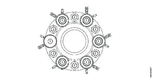
Ensure the two halves of the bolted joint are fully aligned. Number each bolt alternatively “1” and “2”.
Fit the tensioners to all the bolts marked “1”, see also Tensioner Installation for installation instructions.
Using link hoses connect the tensioners together and to a suitable pump unit. See also Tensioner System Configuration for configuration illustrations and for link hose connection instructions. Before connecting a link hose to the pump unit make sure the pump is turned off and the pressure release valve is in the open position.
Ensure the tensioning team is aware of the target “A” pressure (1st pass working pressures) and “B” pressure (2nd pass working pressure). “A” pressures are generally higher than “B” pressures to compensate for load loss. Bolting calculations should only be carried out by trained and qualified engineers who have been appropriately trained or have suitable experience in bolting technology.
For pump operation, refer to the supplied pump instruction document. Operate the pump unit and pressurize the system to 1000psi (70 bar) and check that the pressure is holding steady. If the pressure drops investigate the problem looking for leaks.
Once the pressure is holding steady, continue to pressurize the system up to the target calculated working pressure. Continually monitor for piston over stroke, should any piston over stroke indicator become visible immediately stop the pump to hold the pressure, go to step 9 then 10 then 11. Then recommence the tensioning procedure from step 5.
Once the target “A” (1st pass pressure) is reached, stop the pump to hold pressure. Monitor the pump pressure gauge to ensure the pressure is neither falling nor rising.
Once the pressures is holding steady approach the tensioners and by using a tommy bar inserted into the nut socket holes rotate the nuts firmly against the joint face. Repeat until all of the nuts have been firmly seated against the bolted joint.
Slowly open the pressure relief valve, the pressure will drop to zero.
(OPTIONAL) If the pistons are close to their fully extended position, use a tommy bar inserted into the thread insert and wind down the inserts to close the pistons to their zero stroke position.
Repeat steps 5 through 10 for a second time.
Repeat steps 5 through 10 for a third time.
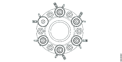
Second pass procedure
Reposition the tensioners on to the remaining 50% of bolts, bolts marked “2” .
Ensure the tensioning team are aware of the target “B” pressure (2nd pass pressure). “B” pressures are generally lower than “A” pressures. Bolting calculations should only be carried out by trained and qualified engineers who have been appropriately trained or have suitable experience in bolting technology.
For pump operation refer to the supplied pump instruction document. Operate the pump unit and pressurize the system to 1000psi (70 bar) and check that the pressure is holding steady. If the pressure drops investigate the problem looking for leaks.
Once the pressure is holding steady, continue to pressurize the system up to the target “B” pressure (2nd pass pressure). Continually monitor for piston over stroke. If the piston over stroke indicator becomes visible on any of the tensioners, immediately stop the pump to hold the pressure. Go to step 18, 19, 20. Then recommence the tensioning procedure from step 15.
Once the target working pressure is reached, stop the pump to hold pressure. Monitor the pump pressure gauge to ensure the pressure is neither fall or rising.
Once the pressures is holding steady approach the tensioners and by using a tommy bar inserted into the nut socket holes rotate the nuts firmly against the joint face. Repeat until all of the nuts have been firmly seated against the bolted joint.
Slowly open the pressure relief valve, the pressure will drop to zero.
(OPTIONAL) If the pistons are close to their fully extended position. Using a tommy bar inserted into the holes in the thread insert head, rotate the thread insert to close the tensioner piston to zero. Repeat until the pistons are fully closed.
Repeat steps 15 through 19 for a second time, to pressure “B”.
Repeat steps 15 through 19 for a third time, to pressure “B”.
Using a tommy bar inserted into the holes in the thread insert head, rotate the thread insert to close the tensioner piston to zero. Repeat until the pistons are fully closed.
Disconnect all hydraulic hoses and remove all tensioners from the bolted joint. The tensioning procedure is considered complete.
Checking Procedure
In order to check if excessive load was lost from the first 50% of bolts (bolts marked “1”).
Install two tensioners on two 1st 50% bolts (marked “1”), diametrically opposite each other.
Connect the hydraulic link hoses.
Pressurize the system to “B” pressure, hold the pressure.
Using a tommy bar inserted into the nut sockets try to tighten down the nuts further by hand:
If there is no further rotation of the nuts, the tensioning sequence is considered complete. Slowly open the pressure relief valve, the pressure will drop to zero. Continue from step 23.
If further nut rotation is achieved, repeat the 1st & 2nd pass tensioning sequence again, steps 2 through 22. Then repeat this checking procedure. If further nut rotation is achieved, repeat the 1st & 2nd pass tensioning sequence again, steps 2 through 22. Then repeat this checking procedure.


