CTST No.5
Tensioner
Product Information
General Information
Safety Signal Words
The safety signal words Danger, Warning, Caution, and Notice have the following meanings:
DANGER | DANGER indicates a hazardous situation which, if not avoided, will result in death or serious injury. |
WARNING | WARNING indicates a hazardous situation which, if not avoided, could result in death or serious injury. |
CAUTION | CAUTION, used with the safety alert symbol, indicates a hazardous situation which, if not avoided, could result in minor or moderate injury. |
NOTICE | NOTICE is used to address practices not related to personal injury. |
Warranty
Product warranty will expire 12+1 months after dispatch from Atlas Copco's Distribution Center.
Normal wear and tear on parts is not included within the warranty.
Normal wear and tear is that which requires a part change or other adjustment/overhaul during standard tools maintenance typical for that period (expressed in time, operation hours or otherwise).
The product warranty relies on the correct use, maintenance, and repair of the tool and its component parts.
Damage to parts that occurs as a result of inadequate maintenance or performed by parties other than Atlas Copco or their Certified Service Partners during the warranty period is not covered by the warranty.
To avoid damage or destruction of tool parts, service the tool according to the recommended maintenance schedules and follow the correct instructions.
Warranty repairs are only performed in Atlas Copco workshops or by Certified Service Partners.
Atlas Copco offers extended warranty and state of the art preventive maintenance through its ToolCover contracts. For further information contact your local Service representative.
For electrical motors:
Warranty will only apply when the electric motor has not been opened.
Website
Information concerning our Products, Accessories, Spare Parts and Published Matters can be found on the Atlas Copco website.
Please visit: www.atlascopco.com.
ServAid
ServAid is a portal that is continuously updated and contains Technical Information, such as:
Regulatory and Safety Information
Technical Data
Installation, Operation and Service Instructions
Spare Parts Lists
Accessories
Dimensional Drawings
Please visit: https://servaid.atlascopco.com.
For further Technical Information, please contact your local Atlas Copco representative.
Safety Data Sheets MSDS/SDS
The Safety Data Sheets describe the chemical products sold by Atlas Copco.
Please consult the Atlas Copco website for more information www.atlascopco.com/sds.
Country of Origin
For the Country of Origin, please refer to the information on the product label.
Dimensional Drawings
Dimensional Drawings can be found either in the Dimensional Drawings Archive, or on ServAid.
Please visit: http://webbox.atlascopco.com/webbox/dimdrw or https://servaid.atlascopco.com.
Overview
Technical Product Data
Technical Product Data can be found on either ServAid, or the Atlas Copco website.
Please visit: https://servaid.atlascopco.com or www.atlascopco.com.
Installation
Installation Requirements
Pre-procedure Checks
Check that each bolt to be tensioned is visually free from obvious thread defects. Make sure all Nuts and Thread Inserts are free to rotate on the bolts. Try a Thread Insert on a bolt and make sure they are correct mating threads.
Ensure there is sufficient stud protruding from the top of the nuts. A minimum of 1 x stud diameter is essential and also a minimum of 2 x D from top of the bolt to the base of the nut.
Also make sure full thread engagement is available through the hexagon nut on the opposite end of the studs being tensioned.
Check that all calculations pertaining to the tensioning procedure, including pressures, bolt loads, etc are available and have been reviewed by a qualified engineer with bolting experience.
Ensure that personnel are fully trained in bolt tensioning procedures and have thoroughly read this guide and safety notes.
Ensure the pump reservoir is filled and an adequate oil volume is available.
Ensure the correct and preferred grade of oil is used in the pump. Refer to the applicable pump product information document. If the incorrect grade of oil is used, the life and performance of the system will deteriorate.
Be sure all personnel are aware of the maximum working pressure and maximum piston stroke of the tensioners. These details are hard stamped on the tensioner bodies
Initial Configuration
Tensioner System Configuration
The most efficient use of bolt tensioning tools is where every bolt (100% bolt to tensioner ratio) is tensioned simultaneously. Tensioners can be fitted to either one side or both sides of the bolted joint depending on accessibility.
Common examples of system configuration are 100% & 50% bolt to tensioner ratio.
This manual details both of these tensioner system configurations.
Operation
Ergonomic Guidelines
Consider your workstation as you read through this list of general ergonomic guidelines to identify areas for improvement in posture, component placement, or work environment.
Take frequent breaks and change work positions frequently.
Adapt the workstation area to your needs and the work task.
Adjust for a convenient reach range by determining where parts and tools need to be located to avoid static load.
Use workstation equipment such as tables and chairs appropriate for the work task.
Avoid work positions above shoulder level or with static holding during assembly operations.
When working above shoulder level, reduce the load on the static muscles by lowering the weight of the tool, using for example torque arms, hose reels or weight balancers. You can also reduce the load on the static muscles by holding the tool close to the body.
Take frequent breaks.
Avoid extreme arm or wrist postures, particularly during operations requiring a degree of force.
Adjust for a convenient field of vision that requires minimal eye and head movements.
Use appropriate lighting for the work task.
Select the appropriate tool for the work task.
In noisy environments, use ear protection equipment.
Use high-quality inserted tools and consumables to minimize exposure to excessive levels of vibration.
Configuration Instructions
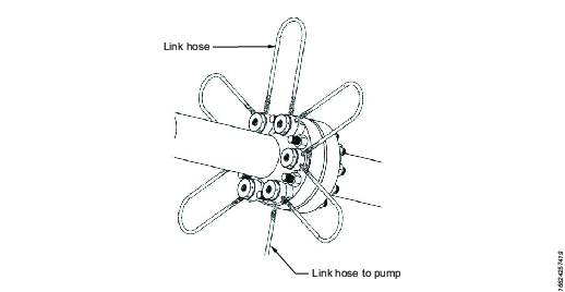
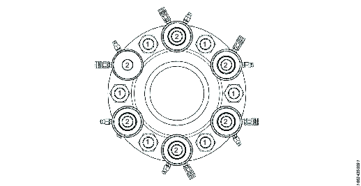
Tensioner Arrangement – 50% Configuration
Every other bolt simultaneously tensioned.
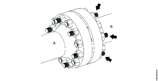
In this configuration the bolt to tensioner ratio is 50%. The tensioning procedure consists of:
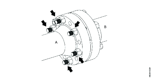
Simultaneously tensioning every other bolt, to first pass pressure “A”
Tension the final 50% of the bolts, to 2nd pass pressure “B”
Optional checking pass.
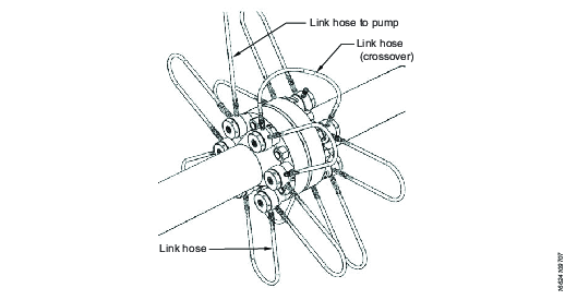
Tensioner Arrangement – 100% Configuration
All bolts simultaneously tensioned.
Commonly, due to space restrictions, it will not be possible to fit tensioners to every bolt from the same side of the bolted joint. It is normal practice to stagger the tensioners over both sides of the bolted joint.
It is normal practice to fit the bolts so adequate thread protrudes from the side of the joint that the tensioner will be fitted.
Operating Instructions
Tensioning Preparation
Make sure the tensioning team have read and understood the “'Insert Type Bolt Tensioner safety information" document.
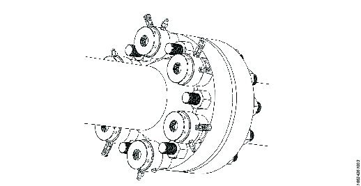
Tensioner Installation
Prior to installing the tensioners see also Pre-procedure Checks to determine the suitable tensioner arrangement to be used.
Prior to installing the tensioners ensure the bolt threads are clean and free of damage.
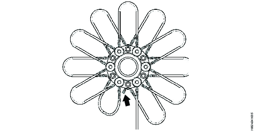
Fit the nut socket over the hexagon nut.

Fit the tensioner over the stud until it sits flat on the bolted joint. Ensure the bridge access window faces radially out with easy accessibility to the tommy holes in the nut socket. Ensure the hydraulic connections are also facing radially outwards.

Place the thread insert into the tensioner bore until contact is made with the top face of the bolt. Using the tommy bar rotate the thread insert downwards until the thread insert head makes contact with the top face of the tensioner piston.

Ensure the pump pressure release valve is fully open and the pump is off. Connect the link hoses to the installed tensioners. See also configuration instructions for different tensioning procedure configurations and illustrations.

Maximum Stroke Indicator
A red line machined into the circumference of the piston indicates the tensioner maximum allowable stroke.
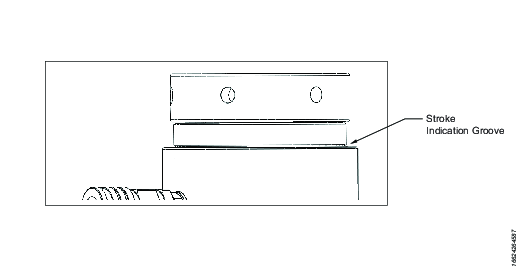
Continually monitor the piston stroke during the tensioner pressurisation.
If the maximum piston stroke indicator becomes visible on any of the tensioners before the target pressure is reached immediately stop the pump, tighten the nuts down and then release the pressure to zero.
Rotate the thread inserts until the pistons are shut down into the zero stroke position.
Recommence the tensioning procedure.
Tensioning procedure 100% bolt to tensioner ratio configuration
Ensure the two halves of the bolted joint are full aligned.
Fit the tensioners to all of the bolts See also Tensioner System Configuration or illustrations of tensioner set up and Tensioner Installation for installation instructions.
Using link hoses connect the tensioners together and to a suitable pump unit. See also Tensioner System Configuration for configuration illustrations and for link hose connection instructions. Before connecting a link hose to the pump unit make sure the pump is turned off and the pressure release valve is in the open position.
Ensure the tensioning team is aware of the target working pressure. Only qualified engineers who have been appropriately trained or have suitable experience in bolting technology should perform bolting calculations.
For pump operation refer to the supplied pump instruction document. Operate the pump unit and pressurize the system to 1000psi (70 bar) and check that the pressure is holding steady. If the pressure drops investigate the problem looking for leaks.
Once the pressure is holding steady, continue to pressurize the system up to the target calculated working pressure. Continually monitor for piston over stroke, should any piston over stroke indicator become visible immediately stop the pump to hold the pressure, go to step 8 then 9 then 10. Then recommence the tensioning procedure from step 5.
Once the target working pressure is reached, stop the pump to hold pressure. Monitor the pump pressure gauge to ensure the pressure is neither falling nor rising.
Once the pressures is holding steady approach the tensioners and by using a tommy bar inserted into the nut socket holes rotate the nuts firmly against the joint face. Repeat until all of the nuts have been firmly seated against the bolted joint.
Slowly open the pressure relief valve, the pressure will drop to zero.
(OPTIONAL) If the pistons are close to their fully extended position, use a tommy bar inserted into the thread inserts and wind down the inserts to close the pistons to their zero stroke position.
Repeat steps 5 through 10 for a second time.
Repeat steps 5 through 10 for a third time.
Using a tommy bar inserted into the holes in the thread insert head, rotate the thread insert to close the tensioner piston to zero. Repeat until the pistons are fully closed.
Dis-connect all hydraulic hoses and remove all tensioners from the bolted joint. The tensioning procedure is considered complete.
Checking Procedure
Pressurize the system for a 4th time and try to seat the hexagon nuts. Use a tommy bar inserted into the nut sockets try to tighten down the nuts further by hand.
If there is no further rotation of the nuts, the tensioning sequence is considered complete. Slowly open the pressure relief valve, the pressure will drop to zero. Continue from step 14.
If further nut rotation is achieved, repeat steps 6 through 11 until no further nut rotation is possible.
De-tensioning procedure 100% bolt to tensioner ratio configuration
See also Tensioning Preparation for the safety instructions.
Fit the Tensioners to the bolts and connect the link hoses. See also Tensioner System Configuration for configuration guide and see Tensioner Installation for an installation guide.
Before commencing pressurization, back off all of the thread inserts by 5mm (0.2”). Ensure there is still enough thread engagement between the thread inserts and the bolt thread protrusions.
For pump operation refer to the supplied pump instruction document. Operate the pump unit and pressurise the system to 1000psi (70 bar) and check that the pressure is holding steady. If the pressure drops investigate the problem looking for leaks.
Once the pressure is holding steady, continue to slowly increase the pressure, continually monitor a single joint nut (tensioner end) for rotation. Use a tommy bar inserted into the nut socket. Once the break loose pressure (BLP) is found, stop the pump to hold the pressure and make a note of the pressure. Once the pressure is holding steady, continue to slowly increase the pressure, continually monitor a single joint nut (tensioner end) for rotation. Use a tommy bar inserted into the nut socket. Once the break loose pressure (BLP) is found, stop the pump to hold the pressure and make a note of the pressure.

Break Loose Pressure (BLP) is the pressure at which the user can rotate one of the joint nuts (tensioner end) by hand.
Make sure the pressure is holding steady and using a tommy bar inserted in the nut socket, back off every joint nut (tensioner end) by 3mm (1/8”). Do not back off the nut to a greater value than the distance that you backed off the thread insert in step 2.
If the nuts are difficult to rotate at this break loose pressure, slightly increase the pressure until the nuts become loose. Never exceed the maximum working pressure of the tensioner. Make sure that the bolt material and joint material can withstand the load you are applying.
Slowly release the pressure to zero.
Using a tommy bar, tighten down the thread inserts to fully close the pistons. Repeat until all of the pistons are fully closed.
Disconnect all hoses and remove all tensioners from the joint.
The de-tensioning procedure is complete.
De-tensioning procedure 50% bolt to tensioner ratio configuration
See also Tensioning Preparation for the safety instructions.
Fit tensioners to every other bolts and connect the link hoses. See also Tensioner System Configuration for configuration guide and see Tensioner Installation for an installation guide.
Before commencing pressurization, back off all of the thread inserts by 5mm (0.2”). Ensure there is still enough thread engagement between the thread inserts and the bolt thread protrusions.
For pump operation refer to the supplied pump instruction document. Operate the pump unit and pressurize the system to 1000psi (70 bar) and check that the pressure is holding steady. If the pressure drops investigate the problem looking for leaks.
Break Loose Pressure (BLP) is the pressure at which the user can rotate one of the joint nuts (tensioner end) by hand.
Once the pressure is holding steady, continue to slowly increase the pressure, continually monitor a single joint nut (tensioner end) for rotation. Use a tommy bar inserted into the nut socket. Once the break loose pressure (BLP) is found, stop the pump to hold the pressure and make a note of the pressure.
Make sure the pressure is holding steady and using a tommy bar inserted in the nut socket, back off every joint nut (tensioner end) by 3mm (1/8”). Do not back off the nut to a greater value than the distance that you backed off the thread insert in step 2.
If the nuts are difficult to rotate at this break loose pressure, slightly increase the pressure until the nuts become loose. Never exceed the maximum working pressure of the tensioner. Make sure that the bolt material and joint material can withstand the load applied.
Slowly release the pressure to zero.
Using a tommy bar, tighten down the thread inserts to fully close the pistons. Repeat until all of the pistons are fully closed.
Reposition the tensioners and link hoses to the remaining 50% of bolts.
Repeat steps 2 through to 7 on the remaining 50% of bolts.
Disconnect all hoses and remove all tensioners from the joint.
The de-tensioning procedure is complete.
Tensioning procedure 50% bolt to tensioner ratio configuration
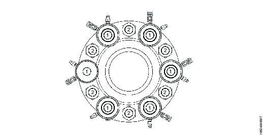
Ensure the two halves of the bolted joint are fully aligned. Number each bolt alternatively “1” and “2”.
Fit the tensioners to all the bolts marked “1”, see also Tensioner Installation for installation instructions.
Using link hoses connect the tensioners together and to a suitable pump unit. See also Tensioner System Configuration for configuration illustrations and for link hose connection instructions. Before connecting a link hose to the pump unit make sure the pump is turned off and the pressure release valve is in the open position.
Ensure the tensioning team is aware of the target “A” pressure (1st pass working pressures) and “B” pressure (2nd pass working pressure). “A” pressures are generally higher than “B” pressures to compensate for load loss. Bolting calculations should only be carried out by trained and qualified engineers who have been appropriately trained or have suitable experience in bolting technology.
For pump operation, refer to the supplied pump instruction document. Operate the pump unit and pressurize the system to 1000psi (70 bar) and check that the pressure is holding steady. If the pressure drops investigate the problem looking for leaks.
Once the pressure is holding steady, continue to pressurize the system up to the target calculated working pressure. Continually monitor for piston over stroke, should any piston over stroke indicator become visible immediately stop the pump to hold the pressure, go to step 9 then 10 then 11. Then recommence the tensioning procedure from step 5.
Once the target “A” (1st pass pressure) is reached, stop the pump to hold pressure. Monitor the pump pressure gauge to ensure the pressure is neither falling nor rising.
Once the pressures is holding steady approach the tensioners and by using a tommy bar inserted into the nut socket holes rotate the nuts firmly against the joint face. Repeat until all of the nuts have been firmly seated against the bolted joint.
Slowly open the pressure relief valve, the pressure will drop to zero.
(OPTIONAL) If the pistons are close to their fully extended position, use a tommy bar inserted into the thread insert and wind down the inserts to close the pistons to their zero stroke position.
Repeat steps 5 through 10 for a second time.
Repeat steps 5 through 10 for a third time.
Second pass procedure
Reposition the tensioners on to the remaining 50% of bolts, bolts marked “2” .
Ensure the tensioning team are aware of the target “B” pressure (2nd pass pressure). “B” pressures are generally lower than “A” pressures. Bolting calculations should only be carried out by trained and qualified engineers who have been appropriately trained or have suitable experience in bolting technology.
For pump operation refer to the supplied pump instruction document. Operate the pump unit and pressurize the system to 1000psi (70 bar) and check that the pressure is holding steady. If the pressure drops investigate the problem looking for leaks.
Once the pressure is holding steady, continue to pressurize the system up to the target “B” pressure (2nd pass pressure). Continually monitor for piston over stroke. If the piston over stroke indicator becomes visible on any of the tensioners, immediately stop the pump to hold the pressure. Go to step 18, 19, 20. Then recommence the tensioning procedure from step 15.
Once the target working pressure is reached, stop the pump to hold pressure. Monitor the pump pressure gauge to ensure the pressure is neither fall or rising.
Once the pressures is holding steady approach the tensioners and by using a tommy bar inserted into the nut socket holes rotate the nuts firmly against the joint face. Repeat until all of the nuts have been firmly seated against the bolted joint.
Slowly open the pressure relief valve, the pressure will drop to zero.
(OPTIONAL) If the pistons are close to their fully extended position. Using a tommy bar inserted into the holes in the thread insert head, rotate the thread insert to close the tensioner piston to zero. Repeat until the pistons are fully closed.
Repeat steps 15 through 19 for a second time, to pressure “B”.
Repeat steps 15 through 19 for a third time, to pressure “B”.
Using a tommy bar inserted into the holes in the thread insert head, rotate the thread insert to close the tensioner piston to zero. Repeat until the pistons are fully closed.
Disconnect all hydraulic hoses and remove all tensioners from the bolted joint. The tensioning procedure is considered complete.
Checking Procedure
In order to check if excessive load was lost from the first 50% of bolts (bolts marked “1”).
Install two tensioners on two 1st 50% bolts (marked “1”), diametrically opposite each other.
Connect the hydraulic link hoses.
Pressurize the system to “B” pressure, hold the pressure.
Using a tommy bar inserted into the nut sockets try to tighten down the nuts further by hand:
If there is no further rotation of the nuts, the tensioning sequence is considered complete. Slowly open the pressure relief valve, the pressure will drop to zero. Continue from step 23.
If further nut rotation is achieved, repeat the 1st & 2nd pass tensioning sequence again, steps 2 through 22. Then repeat this checking procedure. If further nut rotation is achieved, repeat the 1st & 2nd pass tensioning sequence again, steps 2 through 22. Then repeat this checking procedure.
Service
Maintenance Instructions
Seal Replacement
This section details the replacement of “Clip - In” type high pressure seals.

Insert the inner seal into the seal housing; the seal clip fits into the seal clip housing.

Using a blunt nose tool push the seal fully into the seal clip housing, work around the periphery of the seal until the seal is completely inserted into the clip housing.

Insert the outer seal into the seal housing; the seal clip fits into the seal clip housing.

Using a blunt nose tool push the seal fully into the seal clip housing, work around the periphery of the seal until the seal is completely inserted into the clip housing.

Service Recommendations
Preventive maintenance is recommended at regular intervals. See the detailed information on preventive maintenance. If the product is not working properly, take it out of service and inspect it.
If no detailed information about preventive maintenance is included, follow these general guidelines:
Clean appropriate parts accurately
Replace any defective or worn parts
Lubrication Instructions
Tool Storage and Preservation
Atlas Copco standard Airbac tensioner are electroless nickle plated to provide corrosion protection.
During assembly and maintenance of our tensioning tools, threaded components will be lubricated and protected with a thin coating of anti-seize compound, such as copaslip or molyslip, in order to prevent rust forming on the screw threads and to additionally prevent threaded components from seizing together during use.
During assembling and maintenance of Atlas Copco tensioning tools, seals, bearing strips and wiper seals will have the leading edges lubricated with suitable light grease, such as rocol aqua-sil prior to installation, as this will aid assembly.
Tools which have been exposed to water during usage (from rain or similar) should be thoroughly dried before storage. Once packed, all accessible surfaces of the tools will be sprayed with suitable non-drying rust prohibitive oil (for example, shell ensis fluid or castrol rustilo DW300X). This is to make sure that the tools remain rust free through their service life.
Pack the tools into the crate with suitable packaging material to contain them. The standard packing crates that Atlas Copco provide are not water tight and should be covered (under a waterproof tarpaulin or plastic sheeting, for example) if used for longer term storage. The standard packing crates will protect against accidental splashes but are not designed for constant wet conditions.
General Maintenance
Tools will be routinely inspected for any signs of corrosion. It is recommended that tools that have the evidence should be returned to the nearest Atlas Copco service location for refurbishment..
Lifting eyes and straps on tools should be checked before usage for any cracks, tears or any other visible damage. Lifting straps or eyebolts, which are found to be damaged, should not be used.
During storage, it is recommended that all hydraulic fittings have their connected dust caps correctly fitted to prevent any foreign objects getting into the fittings and fouling them.
Tensioners should not be dropped or hit by other hand tools as this risks causing damage to the sealing surfaces of the tool, which can result in tool failure during usage.
The tool coating must be routinely inspected and checked for any evidence of cracking or flaking. It is recommended that tools that have evidence of flaking or cracking be returned to Atlas Copco.
If at any time you have doubts about the operational suitability of a tensioner tool, please contact Atlas Copco for advice.
Atlas Copco recommend that tools are fully refurbished once every 12 months. We can provide a tool refurbishment service for a nominal cost.
Troubleshooting
Troubleshooting Guide
At Start of Shift
Procedure | Acceptance Criteria | Alternative Action |
|---|---|---|
Check that internal and external screw threads of the thread insert are clean and free from burring and notching. | There is no excessive amount of minute solid particles within the lubricating grease residue. The screw threads are complete with no jagged edges or parts of teeth missing. | Clean the screw threads with a suitable solvent to remove the grease residue and any particles contained within. Replace any components where the screw threads are damaged. If in doubt, return to Atlas Copco for assessment. |
Check for cracking on the thread insert. | There are no minute but visible cracks around the radius corners between the shank and flanged head. Neither are there any cracks on the external surface of the shank, in the area where the thread undercut meets the shank. | Replace any components where evidence of cracking is visible. If in doubt, return to Atlas Copco for assessment. |
Check functionality of hydraulic seals. | The load cell assembly may be hydraulically pressurised to maximum working pressure and that pressure maintained for 2-3 minutes. | Remove affected tensioners and contact Atlas Copco for seal replacement. |
Check condition of all hydraulic connectors. | The male and female fittings can be mated and screwed together with ease. There are no pressure leaks between male and female fittings. | The fittings may wear periodically. Replace any fittings that are difficult to mate and screw together. In the event of leakage, check torque values for the fittings in the first instance. If the torque values are satisfactory, return the tensioners to Atlas Copco for replacement of the fittings. |
Check that the hydraulic hoses are free from indentation and bulging. | The polymer coating on the hydraulic hose is not indented in any way. There is no swelling or bulging in the hose. | Replace any damaged hoses immediately. It is not safe to pressurize a damaged hose. |
Check cleanliness and volume of hydraulic fluid. | Fluid should not be excessively discoloured. There should be no particle sediment in the fluid. Volume of fluid in pump reservoir should be to maximum level indicator on sight glass. | Return the pump unit to Atlas Copco for draining, flushing, and re-filling with clean fluid. Top up fluid as required. Use ISO Grade 10, 32 and 68; Shell Morlina oil 10. |
Check functionality of pump on/off valve. | Pump should cycle when valve is in ‘on’ position. Pump cycle should stop immediately without over-run, when valve is switched to ‘off’ position. | Remove pump from process and return to Atlas Copco for repair. |
Check functionality of clutch mechanism on pump pressure release valve. | Valve should allow system to be pressurised when clutch mechanism clicks out. | Remove pump from process and return to Atlas Copco for repair. |
Observe pump workings for signs of fluid leakage. | There should be no wet areas within the pump frame or on any pipework, which may signify leakage through a loose connection. Operate the pump, unconnected, up to 100 bar and hold for 1 minute. There should be no pressure drop on the pressure gauge. | If any fluid leaks are found, remove pump from process and return to Atlas Copco for repair. |
Hydraulic Pressure Gauge should be functional and glass not cracked. | Gauge needle should advance steadily without jumping, and return fully to zero when pressure released. | Remove pump from process and return to Atlas Copco for repair. |
On arrival at new location
Procedure | Acceptance Criteria | Alternative Action |
|---|---|---|
Check that the load cell and thread insert are free of surface rust. | There is no surface rust on all external surfaces of the load cell assembly including the central bore. There is no surface rust on the external surfaces of the thread insert including the internal screw thread. | Lightly brush the affected area with a wire brush. Do not apply excessive force on the load cell assembly to prevent damage to the plating. Apply rust inhibitor to the brushed area of the load cell assembly only, e.g. Ambersil. |
Check torque values for hydraulic connectors. | ¼ x ¼ in BSP adaptor to tensioner and pump hydraulic outlet. Torque: 35Nm Male hydraulic connection to ¼ x ¼ in BSP adaptor. Setting Torque 45Nm. Check Torque 40Nm. Female hydraulic connection to ¼ x ¼ in BSP adaptor to tensioner and pump hydraulic outlet. Setting Torque 45Nm. Check Torque 40Nm. | Use a 17mm AF open-ended wrench fitting to check ¼ x ¼ in BSP adaptor to torque 35Nm. Use a 22mm AF open-ended wrench fitting to check torque on male hydraulic connection. Setting Torque 45Nm. Check Torque 40Nm. Use a 24mm AF open-ended wrench fitting to check torque on female hydraulic connection. Setting Torque 45Nm. Check Torque 40Nm. |
Check hydraulic hoses are free from indentation and bulging. | The polymer coating on the hydraulic hose is not indented in any way. There is no swelling or bulging in the hose. | Replace any damaged hoses immediately. It is not safe to pressurize a damaged hose. |
Check torque values for pump hydraulic outlet female connector. | ¼ x ¼ in BSP adaptor to pump hydraulic outlet. Torque: 35Nm Female hydraulic connection to ¼ x ¼ in BSP adaptor to tensioner and pump hydraulic outlet. Torque 45Nm | Use a 17mm AF open-ended wrench check ¼ x ¼ in BSP adaptor to torque 35Nm. Use a 24mm AF open-ended wrench fitting to check torque on female hydraulic connection. Setting Torque 45Nm. Check Torque 40Nm. |
Recycling
Environmental Regulations
When a product has served its purpose it has to be recycled properly. Dismantle the product and recycle the components in accordance with local legislation.
Disposal
All parts of the tensioner are recyclable. The seals being thermoplastic are therefore suitable to their own form of recycling.
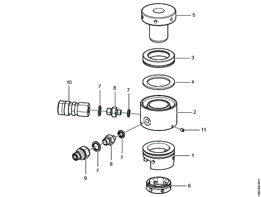
1 | Standard bridge | Recycle |
2 | CTST loadcell body | Recycle |
3 | CTST piston | Recycle |
4 | CTST seal kit | Dispose |
5 | Standard thread insert | Recycle |
6 | Nut rotating socket | Recycle |
7 | BSP dowty bonded seal | Dispose |
8 | Adaptor | Recycle |
9 | Hydraulic nipple | Dispose |
10 | Hydraulic coupling | Dispose |
11 | Socket set screw | Recycle |