SP-2000
Electrical Pump
Product Information
General Information
Safety Signal Words
The safety signal words Danger, Warning, Caution, and Notice have the following meanings:
DANGER | DANGER indicates a hazardous situation which, if not avoided, will result in death or serious injury. |
WARNING | WARNING indicates a hazardous situation which, if not avoided, could result in death or serious injury. |
CAUTION | CAUTION, used with the safety alert symbol, indicates a hazardous situation which, if not avoided, could result in minor or moderate injury. |
NOTICE | NOTICE is used to address practices not related to personal injury. |
Warranty
Product warranty will expire 12+1 months after dispatch from Atlas Copco's Distribution Center.
Normal wear and tear on parts is not included within the warranty.
Normal wear and tear is that which requires a part change or other adjustment/overhaul during standard tools maintenance typical for that period (expressed in time, operation hours or otherwise).
The product warranty relies on the correct use, maintenance, and repair of the tool and its component parts.
Damage to parts that occurs as a result of inadequate maintenance or performed by parties other than Atlas Copco or their Certified Service Partners during the warranty period is not covered by the warranty.
To avoid damage or destruction of tool parts, service the tool according to the recommended maintenance schedules and follow the correct instructions.
Warranty repairs are only performed in Atlas Copco workshops or by Certified Service Partners.
Atlas Copco offers extended warranty and state of the art preventive maintenance through its ToolCover contracts. For further information contact your local Service representative.
For electrical motors:
Warranty will only apply when the electric motor has not been opened.
Website
Information concerning our Products, Accessories, Spare Parts and Published Matters can be found on the Atlas Copco website.
Please visit: www.atlascopco.com.
ServAid
ServAid is a portal that is continuously updated and contains Technical Information, such as:
Regulatory and Safety Information
Technical Data
Installation, Operation and Service Instructions
Spare Parts Lists
Accessories
Dimensional Drawings
Please visit: https://servaid.atlascopco.com.
For further Technical Information, please contact your local Atlas Copco representative.
Safety Data Sheets MSDS/SDS
The Safety Data Sheets describe the chemical products sold by Atlas Copco.
Please consult the Atlas Copco website for more information www.atlascopco.com/sds.
Country of Origin
For the Country of Origin, please refer to the information on the product label.
Dimensional Drawings
Dimensional Drawings can be found either in the Dimensional Drawings Archive, or on ServAid.
Please visit: http://webbox.atlascopco.com/webbox/dimdrw or https://servaid.atlascopco.com.
Overview
Revision History
Revision Date | Changes |
|---|---|
06/2022 |
|
Unpacking and Storage
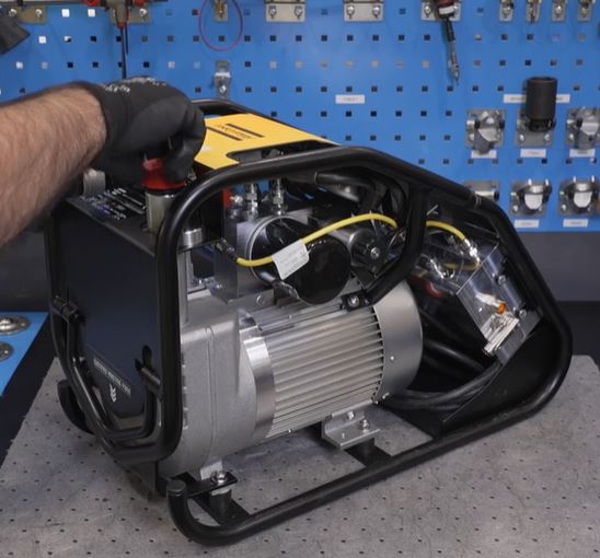
Open the package carefully to avoid damaging fixed accessories, for example, the gauge and the hydraulic connection. Check the contents of the package for obvious damage upon receiving. Check the contents against the delivery note. During transport, the oil filling tube will be plugged with a black cap. After unpacking and setting up the pump for use, replace the black cap with the orange cap.
Storage for less than two months:
Preferably in its original packaging and protected from the elements. If the original package is not available, store it covered with a plastic cover.
Storage for longer than two months:
Preferably in its original packaging, protected from the elements, with a heat sealed plastic cover.
Before storage, if there is any hydraulic oil in the tank, either empty the tank or add a label on the pump showing that it contains oil.
Technical Product Data
Technical Product Data can be found on either ServAid, or the Atlas Copco website.
Please visit: https://servaid.atlascopco.com or www.atlascopco.com.
Installation
Installation Instructions
Pre-Installation Checks
This chapter is a general description of pre-installation checks that needs to be done on the SP2000 pump in order to ensure its continued use.
In case of any concerns about the standard of the equipment or the information in this document, please contact the local Atlas Copco sales representative.
Hydraulic connection
Check the main quick disconnect hydraulic outlet for any dirt ingress. Any ingress must be carefully removed. In case of any concerns about its condition or operation, replace the main quick disconnect hydraulic outlet.
Check that the locking ring functions correctly.
Check the main hydraulic connection for correct connection and operation to a mating connection. If the connection is difficult to make up, or remove, replace the main hydraulic connection.
Hydraulic gauge
Check that the needle on hydraulic gauge reads zero when the hydraulic pump pressure is zero. In case of any doubt about its operation, re-calibrate or replace the hydraulic gauge.
If the front glass is cracked, or if glycerin is leaking, or has leaked, replace the gauge.
Electrical plug socket and cable
The cable must be free from any cuts or tears. No wires should be exposed along its length.
The cable must be securely connected at each end to the pump unit and plug.
In case of any concerns about the security of the cable, or plug socket, replaced the cable or the plug socket.
Communication cable connections
The connections must be secure to the electrical enclosure, without any wiring exposed.
The cable must be free from any cuts or tears. No wires should be exposed along its length.
Oil filler cap
When the pump is in use, use the orange filler cap. The orange cap is breathable allowing air to escape and to eradicate any pressure build up within the oil reservoir.
When the pump is not in use, or when it is transported, use the black filler cap. The black cap is a blanking cap that seals off the oil filling tube and prevents oil spillage.
Frame
Wiping the frame down occasionally can help in identifying any issues.
The hoisting point at the rear of the frame must be without corrosion.
The hoisting point must move freely.
The hoisting point must be secure in its position.
Motor / Powerpack
A general periodic wiping down of the powerpack will help in identifying any issues.
It is extremely important to use the correct grade of oil in order to protect the internal pumping elements of the powerpack.
It is advisable to indicate the oil type/grade that is used by adding an identification label to the assembly.
Do not tamper with the high pressure relief valve and make sure that it has the locking wire in place, see the picture below. The high pressure relief valve is the safety protection valve that prevents the powerpack from being over pressurized.
Point and click on image to see more information:A
The locking wire must be in place
Hoses
See Safety Instructions for Hydraulic Hoses. Printed Matter number is 98392524.
Pump Installation
Main Power Supply Requirement
The pump has a three phase motor with a 16A, 3P+N+E electrical socket.
For the power supply requirements, refer to the table.
Operating frequency | Voltage | Voltage tolerance | Resultant motor power |
|---|---|---|---|
50 Hz | 400 V | ±10% | 1.5 kW |
60 Hz | 440 V | ±10% | 1.8 kW |
Electrical Connections
Before connecting the equipment, check the cables for damage.
The cables must be free from erosions and scrapings.
All the connections must be carried out with elements standardized for this purpose and marked with their electrical characteristics. These electrical characteristics must agree with the characteristics of the power supply and the pressure equipment.
Check that the voltage indicated on the pump ID plate matches the power lead voltage.
If it is necessary to replace the power cable, make sure to assemble it carefully. Before assembling the power cables, put back its insulating sheath and adjust the relevant screws.
Any improper or unauthorized handling of the control box and its internal components can lead to the loss of the warranty and the manufacturer’s responsibility. For this reason it is recommended to send the equipment to the distributer or to contact Atlas Copco Service centers.
Hydraulic Installation
Disconnect the pump from the main power supply.
Fill the oil tank with the suitable grade oil for ambient temperature.

To avoid the oil spillage always use the funnel for oil filling.
Close the oil filling tube with the orange cap.
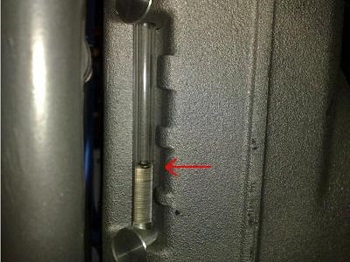
Check the minimum and maximum oil marking level.
Operation
Operating Instructions
The pump has been designed to work with hydraulic tensioners. Before operating the pump, verify the maximum pressure of the tensioner and the hose, as well as compatibility between the connectors.
Check that the hydraulic circuit is properly closed.
Check that the tensioner is correctly placed on the bolts to be tightened.
Check that the personnel involved in the tightening process is on alert and wear adequate personal protective equipment.
Connect the pump to the main supply.
Service
Preventing ESD Problems
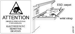
The components inside the product and controller are sensitive to electrostatic discharge. To avoid future malfunction, make sure that service and maintenance is carried out in an ESD approved work environment. The figure below shows an example of an appropriate service work station.
Maintenance Instructions
Service Recommendations
Preventive maintenance is recommended at regular intervals. See the detailed information on preventive maintenance. If the product is not working properly, take it out of service and inspect it.
If no detailed information about preventive maintenance is included, follow these general guidelines:
Clean appropriate parts accurately
Replace any defective or worn parts
Recommended Oil
Ordering number | Product name | Quantity | Temperature range |
|---|---|---|---|
8434204051 | Maximiser 15 | 5 Litre | -15oC < T < 5oC |
8434220002 | Maximiser 32 | 5 Litre | 5oC< T < 25oC |
8434220001 | Maximiser 68 | 5 Litre | 25oC < T < 55oC |
Troubleshooting
Hydraulic Pump does Not Raise the Pressure
Check that the pump is properly connected to the main supply.
Check that there is no sign of alarm in the control box.
Check for leaks in the circuit.
Check if right oil is used as per ambient temperature.
If the motor is running but there is no pressure, plug may be out of phase.
if the motor is running but the pressure does not raise above 200 bar, change the intensifier.
If the pump still does not raise the pressure, contact local Atlas Copco sales representative.
Changing the Hydraulic Oil
It is recommended to change the hydraulic oil after 750 operation hours or after one year depending on what occurs first.
Remove the oil cap from the top of the oil filling tube.
Loosen the plug at the bottom of the tank by using the allen key.

Put back the plug after draining the oil.
If the oil has a dark color, any traces of foam or particles, change both the oil and the filter immediately. Otherwise, the pump could be damaged.
Pay attention to the characteristics of the oil. In case of doubt, contact local Atlas Copco sales representative to avoid using the wrong oil.
Hydraulic Pump does Not Start
Check that the hydraulic pump is properly connected to the main supply.
Check that the hydraulic fluid level is correct.
Check that the power of the generator (if used) is sufficient.
Check that the cross section of the cable is suitable for its length.
If the motor does not run, remove the protective cover from the following switches to check that the switches are on:
Isolater switch on LHS.
Circuit breaker on RHS.
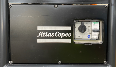
If the hydraulic pump still does not start, contact local Atlas Copco sales representative.
Pay attention if the working conditions are below 10˚C, or if the cable length is very long.
Oil Level Alarm Turns On
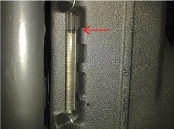
Check that the hydraulic liquid level is in between the minimum and the maximum oil marking level.
Minimum level | Maximum level |
|---|---|
 |  |
Replacing the Oil Filter
It is recommended to replace the oil filter at every oil change or at 1 year intervals along with the oil, unless the oil is contaminated.
When the pump is cool, unscrew the oil filter by turning it counterclockwise and discard it.
Grease the joint of the new filter with the GP (general purpose) grease.
Put the new filter in place by screwing it clockwise until tight.
1 | The oil filter |
Recycling
Environmental Regulations
When a product has served its purpose it has to be recycled properly. Dismantle the product and recycle the components in accordance with local legislation.
Batteries shall be taken care of by your national battery recovery organization.