Product Description
The SP1500 is a portable and automatic hydraulic pump which has been designed for tightening bolts by tensioning process in an industrial environment. It can quickly reach high pressures, significantly saving time in assembly operations. The SP1500 must only be used for the purpose for which it is intended and not for any other purposes not listed in this manual.
One of the features of the SP1500 hydraulic pump is that it can be totally remote-operated using the remote control.. The processes of switching on-off, raising pressure, circuit relief and maintaining the work pressure are always carried out using the remote control. This means that the same operator who inspects the tightening operation can also operate on the pump according to the needs of the tightening process being carried out.
The SP1500 pump is designed to work "continuously" so that once the operator selects the pressure of work and this pressure is achieved by the pump, the machine compensates the possible pressure drops in the circuit due to dilatations or small leaks, therefore maintaining the initially selected pressure.
The SP1500 portable hydraulic pump is a tool designed to work in adverse environmental conditions. To ensure its durability, the tool has an IP-54 degree of protection.
In addition, it is equipped with an oil gauge, temperature control, and light signals in the control box of the hydraulic pump to guarantee a correct and safe use.
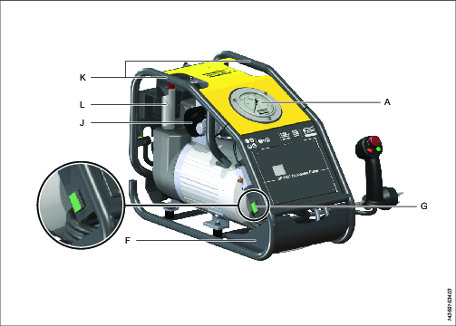
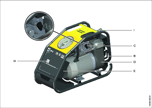
The hydraulic pressure pump is a compact electro-mechanical kit, developed to facilitate its use in different sites. It consists of the following parts:
Submerged electrical motor
Gear pump
Directional solenoid valve
Manifold and secondary solenoid valve
Pressure gauge
Remote control handgrip
Control box
Protective steel frame
Hydraulic oil tank
Pressure regulating manual valve

A: Pressure gauge | G: Main supply switch |
F: Cable rack | J: Filter |
K: Carrying handle | L: Filling tube |

I: Hose connectors | C: Regulating pressure valve |
B: Lifting handle | D: Oil tank |
H: Display | E: control box |
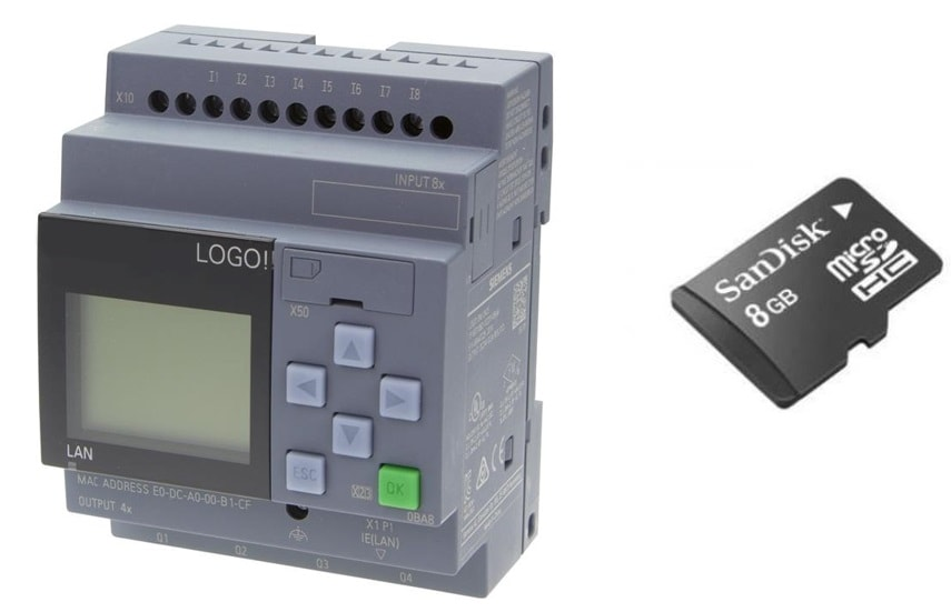
A logic module manages the control of the whole system. It is installed inside the control box.


A: Emergency stop switch | B: Stop and pressure release button |
C: Start and pressure rise button |


