PST5-200CUL
Electromechanical press
Product Information
General Information
Safety Signal Words
The safety signal words Danger, Warning, Caution, and Notice have the following meanings:
DANGER | DANGER indicates a hazardous situation which, if not avoided, will result in death or serious injury. |
WARNING | WARNING indicates a hazardous situation which, if not avoided, could result in death or serious injury. |
CAUTION | CAUTION, used with the safety alert symbol, indicates a hazardous situation which, if not avoided, could result in minor or moderate injury. |
NOTICE | NOTICE is used to address practices not related to personal injury. |
Warranty
Product warranty will expire 12+1 months after dispatch from Atlas Copco's Distribution Center.
Normal wear and tear on parts is not included within the warranty.
Normal wear and tear is that which requires a part change or other adjustment/overhaul during standard tools maintenance typical for that period (expressed in time, operation hours or otherwise).
The product warranty relies on the correct use, maintenance, and repair of the tool and its component parts.
Damage to parts that occurs as a result of inadequate maintenance or performed by parties other than Atlas Copco or their Certified Service Partners during the warranty period is not covered by the warranty.
To avoid damage or destruction of tool parts, service the tool according to the recommended maintenance schedules and follow the correct instructions.
Warranty repairs are only performed in Atlas Copco workshops or by Certified Service Partners.
Atlas Copco offers extended warranty and state of the art preventive maintenance through its ToolCover contracts. For further information contact your local Service representative.
For electrical motors:
Warranty will only apply when the electric motor has not been opened.
Website
Information concerning our Products, Accessories, Spare Parts and Published Matters can be found on the Atlas Copco website.
Please visit: www.atlascopco.com.
ServAid
ServAid is a portal that is continuously updated and contains Technical Information, such as:
Regulatory and Safety Information
Technical Data
Installation, Operation and Service Instructions
Spare Parts Lists
Accessories
Dimensional Drawings
Please visit: https://servaid.atlascopco.com.
For further Technical Information, please contact your local Atlas Copco representative.
Safety Data Sheets MSDS/SDS
The Safety Data Sheets describe the chemical products sold by Atlas Copco.
Please consult the Atlas Copco website for more information www.atlascopco.com/sds.
Country of Origin
For the Country of Origin, please refer to the information on the product label.
Dimensional Drawings
Dimensional Drawings can be found either in the Dimensional Drawings Archive, or on ServAid.
Please visit: http://webbox.atlascopco.com/webbox/dimdrw or https://servaid.atlascopco.com.
Overview
General Description
The PST Servo Electric Press is built on the industry proven QST solution. Our press spindle system delivers high productivity and full commonality for the entire range in many different applications. The highest efficient planetary roller screw has the function to transform the rotational motion, from the unique mechanical gearbox to a powerful and accurate linear motion. The same ToolsTalk PowerMacs software platform makes it easy to use, program and control.
Features
Lean and compact design
Advanced planetary roller screw
Mechanic gear unit instead of belt
Standard QST motor with the smart cable connector
Spindle chip and digital communication
Hardware and software communality with QST
Compatible with ToolsNet
Brake version for parking and hold position (optional)
Benefits
Easy to integrate in limited spaces due to lean and compact design
Extreme durability
Less spare parts inventory
High productivity due to high speeds, accelerations and decelerations
Installation and training cost reduction
Part of Smart Connected Assembly
Applications
PST is an electromechanical actuator which can be used for assembling for example bearings, seals, gears or alignment pins when high accuracy and traceability is needed. You can press to a stop and control the force of the actuator, or you can press to a certain distance and control the stroke of the actuator.
Main components
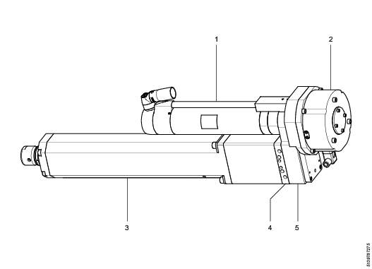
1 | Motor | 4 | Load cell |
2 | Brake (CBUL only) | 5 | Gearbox |
3 | Roller Screw housing assembly |
Normal Environmental Conditions
This product is designed to be safe under the following conditions:
Indoor use
Altitude up to 2 000 m
Ambient temperature 0°C to 40 °C
Maximum relative humidity 80 % for temperatures up to 31 °C decreasing linearly to 50 % relative humidity at 40 °C
Pollution degree 2
Technical Product Data
Technical Product Data can be found on either ServAid, or the Atlas Copco website.
Please visit: https://servaid.atlascopco.com or www.atlascopco.com.
Accessories
Optional Accessories
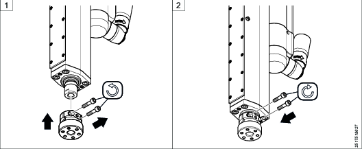
Press Tool Adapter for PST
The press tool adapter allows customer tooling to be set in a specific angle around the pressing axis.
It should be used for applications with pulling forces.
Remove the two screws (2x) and assemble the press tool adapter on to the press piston.
Assemble the two (2x) screws and tighten according to table.
Press Force Transducer
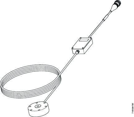
The press force validation transducer is used together with the STanalyser/STa 6000 to measure press force in the actual application, to calibrate the PST to the actual application or as a regular quality control of the PST. See STanalyzer/STa 6000 documentation for operating instructions.
TTS-QST Programming Cable
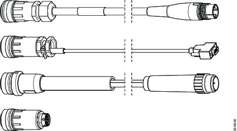
The TTS programming cable is used for programming QST/PST tools when motor or load cell have been changed.
Service Overview
Service Recommendations
Preventive maintenance is recommended at regular intervals. See the detailed information on preventive maintenance. If the product is not working properly, take it out of service and inspect it.
If no detailed information about preventive maintenance is included, follow these general guidelines:
Clean appropriate parts accurately
Replace any defective or worn parts
Spare parts
For spare parts inquiries see ServAid.
Installation
Installation Requirements
Requirements
The PST press is intended for use as a machine or machinery component. The responsibility for handling, installation and use of this product lies with the MTB (Machine Tool Builder) and end-user.
The MTB or site responsible must always perform a risk assessment according to ISO 13849-1, to determine the required performance level for the complete installation.
Installation, operation and service of the PST Press must only be done by qualified personnel.
Installation Instructions
Installation overview
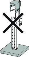
The PST press can be installed by the use of the front screw holes or the rear screw holes. See the dimensional drawings on ServAid for installation dimensions.
Lubricant | Description |
|---|---|
Klüberlub® BE 71-501 | http://www.klueber.com/en/product-detail/id/404/ |
Screw | Torque [Nm] | Torque [ft·lb] |
|---|---|---|
M3 | 1,7 | 1,25 |
M4 | 4,0 | 2,95 |
M5 | 7,5 | 5,53 |
M6 | 13 | 9,59 |
M8 | 30 | 22,13 |
M10 | 60 | 44,25 |
M12 | 110 | 81,13 |
M14 | 180 | 133 |
M16 | 280 | 206,52 |
Oil the threaded parts of the screw before tightening.
Only use screws with strength class 12.9 (DIN 912).
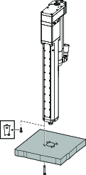
Vertical installation front mounting
Press | Front mounted |
|---|---|
PST 5 | M8 (4x) |
PST10 | M8 (4x) |
PST20 | M8 (8x) |
PST35 | M10 (8x) |
PST50 | M10 (8x) |
PST60 | M10 (8x) |
PST100 | M12 (8x) |
Required tools
Allen keys or bits 4-10 mm
Screw bits and sockets
Torx® keys or bits T6-T25
Torque wrench
Lifting device
Screwdrivers
Pliers
Bearing puller (optional)
Feeler gauge
Fit a lifting eye in the rear end of the press, see dimensional drawings in ServAid.
Unscrew the screws in the front end of the press.
Lift the press to a vertical position.
Assemble the press to the mounting plate using new longer screws.

See dimensional drawings in ServAid for the screw length.
Radial force on press piston

Max allowed Press tooling weight (mass) for vertical installation
PST Press Model | With Brake (kg) | With brake (lbs) | Without brake (kg) | Without brake (lbs) |
|---|---|---|---|---|
PST5 | 25 | 55 | 8 | 17,6 |
PST10 | 50 | 110 | 8 | 17,6 |
PST20 | 100 | 220 | 16 | 35,5 |
PST35 | 175 | 385 | 28 | 61,6 |
PST50 | 250 | 550 | 40 | 88 |
PST60 | 250 | 550 | 40 | 88 |
PST100 | 500 | 1100 | 80 | 176 |
Required tools
Allen keys or bits 4-10 mm
Screw bits and sockets
Torx® keys or bits T6-T25
Torque wrench
Lifting device
Screwdrivers
Pliers
Bearing puller (optional)
Feeler gauge
Fit a lifting eye in the rear end of the press.
Lift the press to a vertical position.
Fix the press and tighten screws diagonal to specified torque.
Vertical installation rear mounting

Press | Rear mounted |
|---|---|
PST 5 | M8 (8x) |
PST10 | M8 (8x) |
PST20 | M10 (8x) |
PST35 | M10 (8x) |
PST50 | M12 (8x) |
PST100 | M16 (8x) |
Required tools
Allen keys or bits 4-10 mm
Screw bits and sockets
Torx® keys or bits T6-T25
Torque wrench
Lifting device
Screwdrivers
Pliers
Bearing puller (optional)
Feeler gauge
Use holes on both sides of the press when using rear screw holes

Do not use too long screws, see dimensional drawings in ServAid.
Tighten the screws according to the Torque table .

Make sure to support the press until all screws are tightened.
Horizontal installation
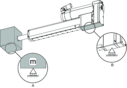
Press | Tool weight max. (A) | Press support need (B) |
|---|---|---|
PST 5 | 2 Kg | No |
PST 10 | 2 Kg | No |
PST 20 | 4 Kg | Yes (CBUL only) |
PST 35 | 7 Kg | Yes |
PST 50 | 10 Kg | Yes |
PST 55 | 10 Kg | Yes |
PST 100 | 20 Kg | Yes |
Installing the Motor Cable
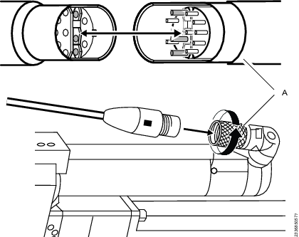
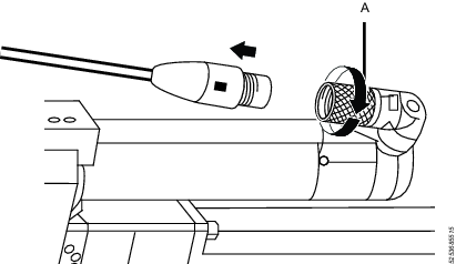
Align the motor cable with the pins on the press contact.
Push the motor cable gently towards the beginning of the threads.
Turn the handle (A) clockwise to install and lock the motor cable.
Service
Preventing ESD Problems
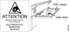
The components inside the product and controller are sensitive to electrostatic discharge. To avoid future malfunction, make sure that service and maintenance is carried out in an ESD approved work environment. The figure below shows an example of an appropriate service work station.
Maintenance Instructions
Precautions
Turn the handle (A) counter clockwise to release the motor cable.
Pull out the motor cable.
Service Requirements
Service must only be carried out by qualified personnel who have access to the Service Instruction and/or have been trained for service on Atlas Copco tools.
The electric motor is a sealed unit and may under no circumstances be opened by other than Atlas Copco Industrial Technique AB. When determined that the electric motor is defected or in need of service, the complete motor unit should be returned to Atlas Copco for exchange. Motors which have been opened by other than Atlas Copco will not be serviced.
Service Recommendations
Preventive maintenance is recommended at regular intervals. See the detailed information on preventive maintenance. If the product is not working properly, take it out of service and inspect it.
If no detailed information about preventive maintenance is included, follow these general guidelines:
Clean appropriate parts accurately
Replace any defective or worn parts
Preventive Maintenance
Maintenance Intervals
In normal operating conditions, which is 80% load and a motor temperature of max 80 °C, the press should be serviced at regular intervals after 1 million cycles or once a year.
Lubrication Instructions
Required lubricants
Lubricant | Description |
|---|---|
Klüberlub® BE 71-501 | http://www.klueber.com/en/product-detail/id/404/ |
Preparing for the Lubrication
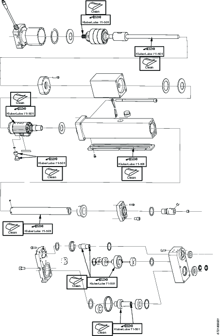
Before lubrication, run the press to maximum out position (minus 5 mm), or as far as the installation permits, to expose the internal threaded part of the roller screw.
Power off the system with the press in this out position.
For preventive maintenance you do not need to remove the roller screw housing assembly from the gear box.
Lubrication guide
Lubricant | Description |
|---|---|
Klüberlub® BE 71-501 | http://www.klueber.com/en/product-detail/id/404/ |
Lubrication of roller screw
Always read and follow the instruction Preparing for the Lubrication.
Lubricant | Description |
|---|---|
Klüberlub® BE 71-501 | http://www.klueber.com/en/product-detail/id/404/ |
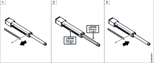
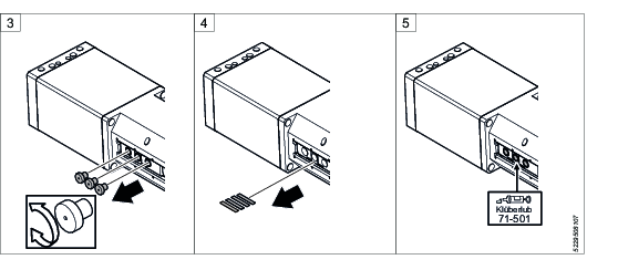
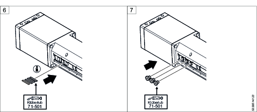
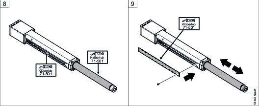
Remove the cover and wipe off grease from the inside using paper or a cloth.
Add enough grease to fill the threads evenly onto the visible part of the roller screw.
Reassemble the cover.
Lubrication of roller screw housing guides and guide rollers
Add a small amount of grease (Klüberlub® BE 71-501) on all surfaces during reassembly.
Lubricant | Description |
|---|---|
Klüberlub® BE 71-501 | http://www.klueber.com/en/product-detail/id/404/ |
Remove the cover and wipe off grease from the inside using lint-free cloth.
Check for excessive wear.
Check:
the guides on the inside of the cover
the roller bearing surfaces
the roller screw surface
Look for irregular rotation by rotating the guide rollers in the roller bearings before removal.
If the roller bearings are damaged, change all roller bearings see Changing the roller bearings.
Remove leaf springs.
Add a small amount of grease (Klüberlub® BE 71-501) on the guide roller bearings .
Add a small amount of grease (Klüberlub® BE 71-501) and assemble the leaf springs.
Assemble the guide rollers, add a small amount of grease (Klüberlub® BE 71-501).
Lubricate the roller screw using grease (Klüberlub® BE 71-501).
Add a small amount of grease (Klüberlub® BE 71-501) on the inside of the cover and reassemble roller screw housing. Cycle the press from max OUT position to max IN position five times at 10mm/s to distribute the grease.

Light force may be needed to fit the center guide roller holder.

Repair Instructions
Replacing the Communication Card Tube
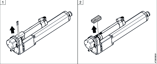
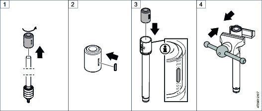
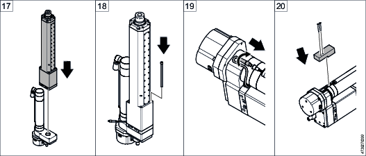
Replacement of card should only be performed by authorized service personnel who have received proper training. There is no need to disassemble the motor back part for replacement of the communication card.
Dismantling/Assembling Instructions
Disassembling the screw housing
Required tools
Allen keys or bits 4-10 mm
Screw bits and sockets
Torx® keys or bits T6-T25
Torque wrench
Lifting device
Screwdrivers
Pliers
Bearing puller (optional)
Feeler gauge
Lubricant | Description |
|---|---|
Klüberlub® BE 71-501 | http://www.klueber.com/en/product-detail/id/404/ |
Remove the connector cover screws.
Disassemble the connector cover.
Disconnect the load cell cable from the motor cable.
Fix the press by clamping over the gearbox housing using a soft vice.
Unscrew the bolts (4x) holding the screw housing assembly to the gearbox.

Discard used bolts.
Slide the screw housing assembly out of the spline joint in the gearbox.

The guide ring can be placed seated in the gearbox.
Place the press on a horizontal surface.
Disassemble all the cover screws.
Disassemble the cover.
Disassemble the guide rollers (3x).
Disassemble all leaf springs (up to 4x).

If less than 4 leaf springs, increase to 4 pcs at reassembly.
Disassemble the screw housing.
Disassemble the center roller holder.
Unscrew the screw nut and piston shaft assembly, by rotating the whole assembly of the inner shaft.
Disassemble the upper disc spring (and support washer).
Disassemble the outer bearing cover (towards the roller screw nut).
Clamp over load cell/housing in a vice using soft jaws.
Unscrew all bolts holding the load cell.
Disassemble the Inner bearing cover from roller screw shaft.
Disassemble the roller screw bearing disc spring and all washers.
Unscrew all the bolts and disassemble the upper flange.
Slide the roller screw nut out of the roller nut housing.

Make sure to remove the shaft key that connects the two parts to use at reassembly.
Screw the roller screw nut back onto the roller screw shaft.

Roller screw shaft and nut are a matched pair, each marked with a serial number.

Some of the steps are not needed at roller screw replacement.
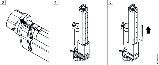
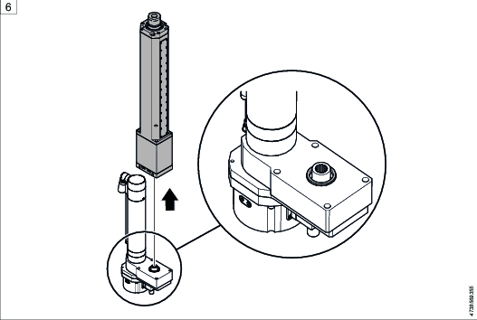
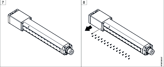
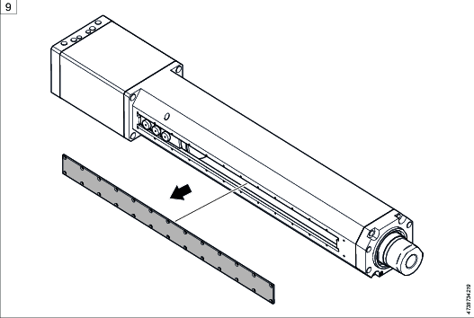
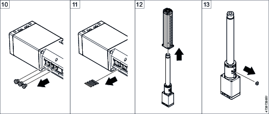
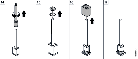
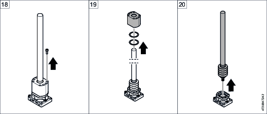
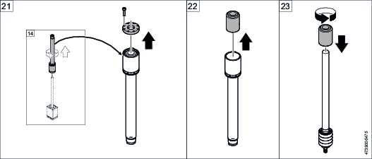
Disassembling the gearbox
Required tools
Allen keys or bits 4-10 mm
Screw bits and sockets
Torx® keys or bits T6-T25
Torque wrench
Lifting device
Screwdrivers
Pliers
Bearing puller (optional)
Feeler gauge
Lubricant | Description |
|---|---|
Klüberlub® BE 71-501 | http://www.klueber.com/en/product-detail/id/404/ |
Remove the screws holding the connector cover.
Disassemble the connector cover.
Disconnect the load cell cable from the motor cable.
Fix the press over the gear box in a vice using soft jaws.
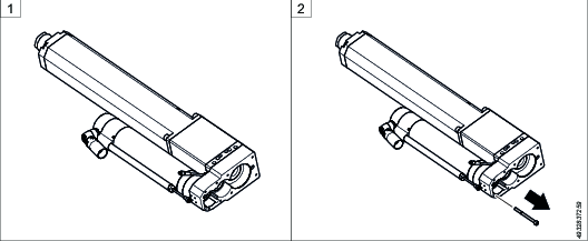
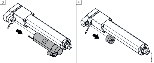
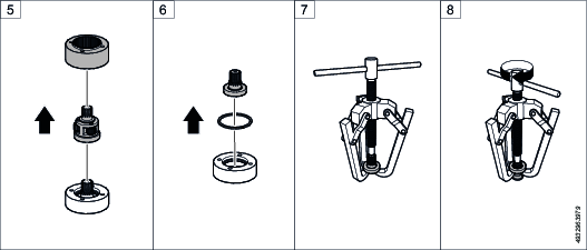
Disassemble the brake pic. 2-3 (CBUL press only).
Unscrew the top cover screws.
Remove the top cover by screwing long screws through the threaded holes.

Remember the position of the guide rings and the preload washers. The preload washers can be placed in the top cover.
Disassemble the guide rings and the preload washers.
Disassemble the gear wheels, axis and bearings.
Disassemble all bearings (x6) using a bearing puller (pic. 10-11).
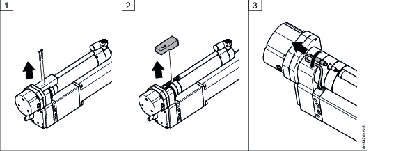
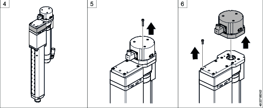
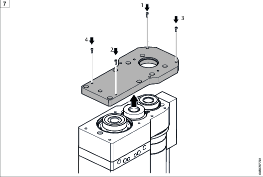
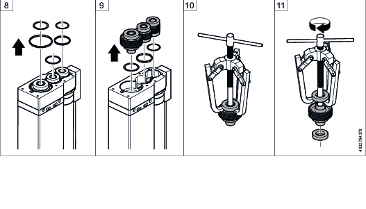
Changing the roller bearings
Required tools
Allen keys or bits 4-10 mm
Screw bits and sockets
Torx® keys or bits T6-T25
Torque wrench
Lifting device
Screwdrivers
Pliers
Bearing puller (optional)
Feeler gauge
Lubricant | Description |
|---|---|
Klüberlub® BE 71-501 | http://www.klueber.com/en/product-detail/id/404/ |
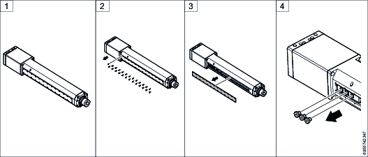
Place the press on a horizontal surface.
Disassemble all the screw housing cover screws.
Disassemble the screw housing cover.
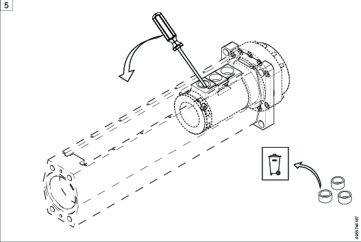
Disassemble the guide rollers and the shim (3x).
Disassemble the roller bearings (3x).

Discard the used roller bearings.
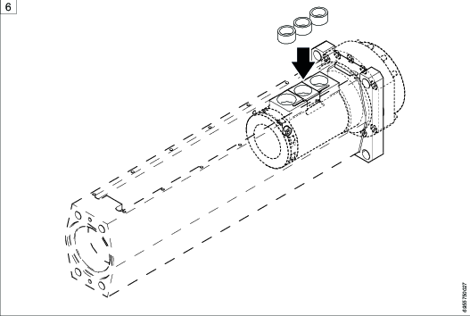
Assemble the new roller bearings (3x).

Apply a thin layer of grease (Klüberlub® BE 71-501) on all parts.
Assemble the guide rollers and the shim (3x)

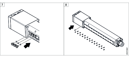
Apply a thin layer of grease (Klüberlub® BE 71-501) on all parts.
Assemble the screw housing cover using the screws.
Disassembling the motor and the planetary gear
Required tools
Allen keys or bits 4-10 mm
Screw bits and sockets
Torx® keys or bits T6-T25
Torque wrench
Lifting device
Screwdrivers
Pliers
Bearing puller (optional)
Feeler gauge
Lubricant | Description |
|---|---|
Klüberlub® BE 71-501 | http://www.klueber.com/en/product-detail/id/404/ |
First, disassemble the gearbox, see Disassembling the gearbox.
Place the press on a horizontal surface before loosening the screws.
Unscrew the screws that holds the planetary gear and motor.
Disassemble the gear rim.
Disassemble the planetary gear (only applicable in PST 35, PST50 and PST100).
Disassemble the circlip in the gear housing (only applicable in PST 35, PST50 and PST100).
Disassemble the sun gear and bearing (only applicable in PST 35, PST50 and PST100).
Disassemble the sun gear bearing using a bearing puller. (Pic. 7- 8 only applicable in PST 35, PST50 and PST100).
Assembling the screw housing
Required tools
Allen keys or bits 4-10 mm
Screw bits and sockets
Torx® keys or bits T6-T25
Torque wrench
Lifting device
Screwdrivers
Pliers
Bearing puller (optional)
Feeler gauge
Lubricant | Description |
|---|---|
Klüberlub® BE 71-501 | http://www.klueber.com/en/product-detail/id/404/ |
Required spare parts
Spare parts | Amount |
|---|---|
Roller bearings | 3 |
Leaf springs | 3 |
Shim rings | 4 |
Rollers | 3 |
Shaft seal (o-ring or scraper seal) | 3 |
Glide bearing | 1 |
Load cell (if needed) | 1 |
Unscrew the roller screw nut from the roller screw shaft delivered from SKF.
Assemble the shaft key on to the roller screw nut.
Add a small amount of grease to all surfaces and slide the roller screw nut into the roller nut housing.
Clamp over roller nut housing using a vice with soft jaws.
Assemble the upper flange using new screws.

Tighten the screws crosswise, first to 50% torque, then to 100% torque. Torque according to Installation overview.
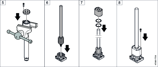
Assemble the roller screw bearing, disc spring and all washers.

Assemble the convex side of disc spring towards the bearing. Use washer(s) between housing and disc spring.
Assemble the shim, washer and the Inner bearing cover onto the roller screw shaft.
Assemble the load cell using new screws. Tighten the screws crosswise using a long hexagon socket, first to 50% torque, then to 100% torque. Torque according to Installation overview.

Clamp over load cell/housing using a vice with soft jaws.
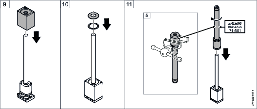
Assemble the outer bearing cover.
Assemble the upper disc spring (and support washer).

Convex side towards gearbox. Washer between housing and disc spring.
Assemble the screw nut and piston shaft assembly by rotating the whole assembly onto the inner shaft.

Apply a thin layer of grease (Klüberlub® BE 71-501) on the screw.
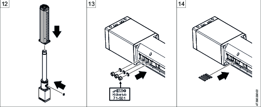
Assemble the center roller holder and the screw housing.
If needed, assemble the glide bearing, the shim rings (3x) and the roller bearings (3x), see Changing the roller bearings.

Apply a thin layer of grease (Klüberlub® BE 71-501) on all parts.
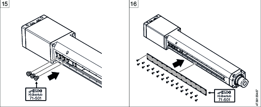
Assemble the leaf springs (4x).

Apply a thin layer of grease (Klüberlub® BE 71-501) on all parts.
Assemble the guide rollers (3x).

Apply a thin layer of grease (Klüberlub® BE 71-501) on all parts.
Assemble the front cover using the screws.
Slide on the screw housing assembly onto the spline joint in gearbox.
Assemble the screw housing assembly to the gearbox using new bolts (4x).

Tighten the screws crosswise, first to 50% torque, then to 100% torque. Torque according to Installation overview.
Assemble the load cell cable onto the motor cable.
Assemble the connector cover using the screws (2x).
Assembling the gearbox
Required tools
Allen keys or bits 4-10 mm
Screw bits and sockets
Torx® keys or bits T6-T25
Torque wrench
Lifting device
Screwdrivers
Pliers
Bearing puller (optional)
Feeler gauge
Lubricant | Description |
|---|---|
Klüberlub® BE 71-501 | http://www.klueber.com/en/product-detail/id/404/ |
Required spare parts
Bearings (x6)
Assemble the bearings on both sides using a press and support (x6).

Only press and support on the bearing inner rings.

Apply a thin layer of grease (Klüberlub® BE 71-501).
Assemble the guide rings.
Assemble the preload washers into the top cover.
Assemble the top cover using new screws.

Tighten the screws crosswise, first to 50% torque, then to 100% torque. Torque according to Installation overview.
Assemble the brake pic. 6-7 (CBUL press only).

Assembling the planetary gear and the motor
Required tools
Allen keys or bits 4-10 mm
Screw bits and sockets
Torx® keys or bits T6-T25
Torque wrench
Lifting device
Screwdrivers
Pliers
Bearing puller (optional)
Feeler gauge
Lubricant | Description |
|---|---|
Klüberlub® BE 71-501 | http://www.klueber.com/en/product-detail/id/404/ |
Required spare parts
Sun gear bearing
Planetary gear
Sun gear
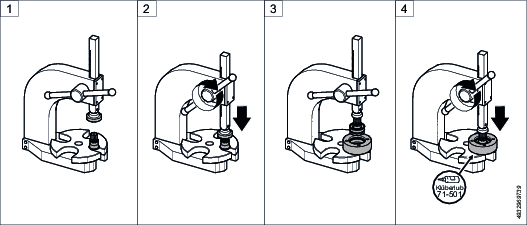
Assemble the sun gear bearing onto the sun gear axis using a press (only applicable in PST 35, PST50 and PST100), frame 1-2.

Only push on the inner ring of the bearing using the press.
Assemble the sun gear and bearing into the gear housing using a press (only applicable in PST 35, PST50 and PST100), frame 3-4.

Only push on the outer ring of the bearing using the press.

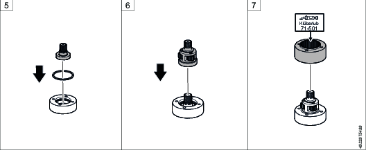
Apply a thin layer of grease (Klüberlub® BE 71-501).
Assemble the circlip in gear housing using a pliers (only applicable in PST 35, PST50 and PST100), frame 5.
Assemble the new planetary gear (only applicable in PST 35, PST50 and PST100), frame 6.
Assemble the gear rim (only applicable in PST 35, PST50 and PST100), frame 7.

Apply a thin layer of grease (Klüberlub® BE 71-501) to the screw.
Assemble the planetary gear (only applicable in PST 35, PST50 and PST100), frame 8.
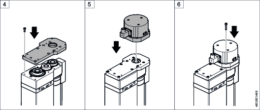
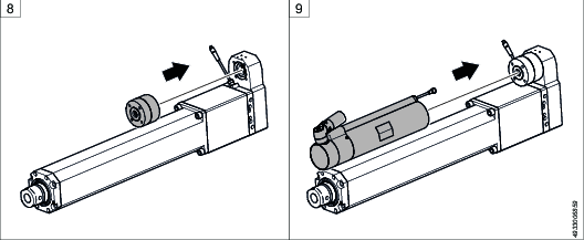
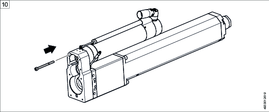
Assemble the motor, using new screws frame 9 -10.

Tighten the screws crosswise, first to 50% torque, then to 100% torque. Torque according to Installation overview.
Recycling
Environmental Regulations
When a product has served its purpose it has to be recycled properly. Dismantle the product and recycle the components in accordance with local legislation.
Batteries shall be taken care of by your national battery recovery organization.
Recycling information for press tool
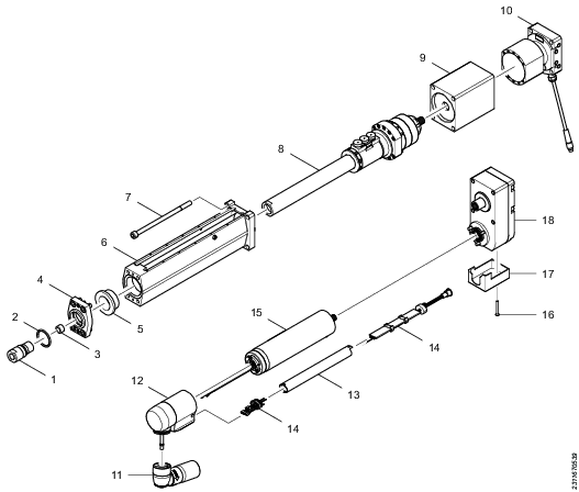
Pos. | No. | Part. | Recycle as: |
|---|---|---|---|
1 | 1 | Adapter | Metal, Steel |
2 | 1 | O-ring/Scraper | NBR rubber |
3 | 1 | Silencer | Metal, Brass |
4 | 1 | Plate | Metal, Steel |
5 | 1 | Bearing | Metal, Bronze |
6 | 1 | Housing | Metal, Aluminum |
7 | 4 | Screw | Metal, Steel |
8 | 1 | Push rod | Metal, Steel |
9 | 1 | Housing | Metal, Steel |
10 | 1 | Load cell | Metal, Steel |
11 | 1 | Connector | Electronic |
12 | 1 | Motor back part | Metal, Aluminum |
13 | 1 | Com. card tube | Metal, Stainless steel |
14 | 1 | Com. card (PCB) | Electronic |
15 | 1 | Motor | Electronic |
16 | 2 | Screw | Metal, Steel |
17 | 1 | Cover | Metal, Aluminum |
18 | 1 | U-gear and Screws | Metal, Steel |
