WP-105 Balancers
Balancer
Product Information
General Information
Safety Signal Words
The safety signal words Danger, Warning, Caution, and Notice have the following meanings:
DANGER | DANGER indicates a hazardous situation which, if not avoided, will result in death or serious injury. |
WARNING | WARNING indicates a hazardous situation which, if not avoided, could result in death or serious injury. |
CAUTION | CAUTION, used with the safety alert symbol, indicates a hazardous situation which, if not avoided, could result in minor or moderate injury. |
NOTICE | NOTICE is used to address practices not related to personal injury. |
Warranty
Product warranty will expire 12+1 months after dispatch from Atlas Copco's Distribution Center.
Normal wear and tear on parts is not included within the warranty.
Normal wear and tear is that which requires a part change or other adjustment/overhaul during standard tools maintenance typical for that period (expressed in time, operation hours or otherwise).
The product warranty relies on the correct use, maintenance, and repair of the tool and its component parts.
Damage to parts that occurs as a result of inadequate maintenance or performed by parties other than Atlas Copco or their Certified Service Partners during the warranty period is not covered by the warranty.
To avoid damage or destruction of tool parts, service the tool according to the recommended maintenance schedules and follow the correct instructions.
Warranty repairs are only performed in Atlas Copco workshops or by Certified Service Partners.
Atlas Copco offers extended warranty and state of the art preventive maintenance through its ToolCover contracts. For further information contact your local Service representative.
Website
Information concerning our Products, Accessories, Spare Parts and Published Matters can be found on the Atlas Copco website.
Please visit: www.atlascopco.com.
ServAid
ServAid is a portal that is continuously updated and contains Technical Information, such as:
Regulatory and Safety Information
Technical Data
Installation, Operation and Service Instructions
Spare Parts Lists
Accessories
Dimensional Drawings
Please visit: https://servaid.atlascopco.com.
For further Technical Information, please contact your local Atlas Copco representative.
Safety Data Sheets MSDS/SDS
The Safety Data Sheets describe the chemical products sold by Atlas Copco.
Please consult the Atlas Copco website for more information www.atlascopco.com/sds.
Country of Origin
For the Country of Origin, please refer to the information on the product label.
Dimensional Drawings
Dimensional Drawings can be found either in the Dimensional Drawings Archive, or on ServAid.
Please visit: https://webbox.atlascopco.com/webbox/dimdrw or https://servaid.atlascopco.com.
General safety
Please read the instructions for use before using the balancer. Safe working with the machine is only possible if you have read the instructions for use and safety information in full, have understood the instructions contained therein and observe them strictly.
Never remove safety devices like Safety suspension (2), (3) or Load hook (9)), or deactivate them by modification. In the event of a fault or defect, stop using the balancer and inform the responsible supervisor. This is the case, for example, when a balancer falls into the chain. Further use must be assessed by trained and qualified personnel and damaged components must be replaced.
The operator must trained before working with the balancer in accordance with the instructions given in these instructions for use.
Overview
Application
The balancer is used for relieving the weight of hand-held tools and makes the use of the hand-held and simple multi-fixtured tools much easier.
The retraction forces remains nearly constant over the whole wire extension length. The load range differs depending on model.
The ambient temperature for the use of the balancer is -20°C to +70°C.
Technical Product Data
Technical Product Data can be found on either ServAid, or the Atlas Copco website.
Please visit: https://servaid.atlascopco.com or www.atlascopco.com.
If the Technical Product Data is not available on either website, please contact the local Atlas Copco Customer Center for assistance.
Main components
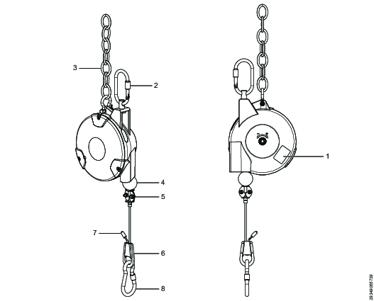
CE label
Suspension hook
Chain
Wire stop buffer
Wire clamp
Wire wedge
Ferrule
Trigger Snap
Installation
Installation Instructions
Installing the balancer
Install the balancer so it can easily be aligned and moved in any direction. The wire must to be able to move without any additional force.

If a cable or any other accessory is attached to the wire, it might shorten the lifetime of the wire, and this may cause the wire to break due to fatigue. Do not attach a tool cable or any accessory to the balancer wire without consulting Atlas Copco.
Install the supplied auxiliary chain.
Make sure that the auxiliary chain is not too long or too short to interfere with the balancer across its entire working area.
The chain is always mounted on a separate mounting point from the balancer to prevent risks.
The permitted maximum falling distance is 100 mm.
Before installation make sure that the balancer suspension attachment and the auxiliary chain fixture is safe and stable.
Attach the workload to the snap hook at the cable end.
Adjust the workload, see “Adjusting the workload”.
Adjusting the workload
The balancer is factory set to carry a maximum workload.
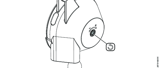
To adjust the balancer to carry different workloads, turn the endless screw on the balancer in minus (-) or plus (+) direction.
(-) for lighter workload
(+) for heavier workload
Attach the workload on the snap hook.
Turn the endless screw in minus (-) or plus (+) direction to adjust the counterbalance weight.
To turn the endless screw use a hexagon key for WP 105; press and turn
Setting the initial tension of the balancer
The initial tension of the balancer need to be set if the spring has been released during service.
To get the maximum initial tension of the balancer, turn the endless screw in the plus (+) direction x number of times, refer to the table below.
4390190173 | x = approx 11 |
4390190174 | x = approx 5 |
4390190175 | x = approx 6 |
4390190176 | x = approx 5 |
4390190178 | x = approx 4 |
4390190179 | x = approx 11 |
4390190180 | x = approx 5 |
4390190181 | x = approx 6 |
4390190182 | x = approx 5 |
4390190183 | x = approx 4 |
Setting the minimum workload
When setting the minimum workload, never use a wire length of more than 1.0 m as the spring fracture device may release.
If the spring fracture device releases:
Carefully adjust the spring tension in the (+) direction.
Attach the workload.
Adjust the counterbalance weight of the workload by turning the endless screw in the minus (-) direction.
Locking the wire drum
The drum lock blocks the wire drum. When the wire drum is locked it is possible to replace the wire without decreasing the spring tension.
Push the drum lock fixing pin as far as possible and turn it 90° using a flat screwdriver.
Make sure that the wire drum is locked.
Unlock the wire drum by turning the drum lock fixing pin back to the start position.
Make sure that the workload is attached and the spring tension is adjusted before unlocking the drum.
Adjusting the wire extension length
Maintain a minimum distance of 100 mm between wire wedge (6) and wire clamp (5) during installation. Otherwise, increased wear and premature failure are possible.
Loosen the wire clamp.
Move the wire clamp and wire stop buffer to the wanted position.
Tighten the wire clamp.
Adjusting the wire length
Only applicable to WP models that have a wedge adjustment at the lower attachment point.
The balancer is delivered with a long wire so that the wire length can be adjusted to the on-site circumstances.
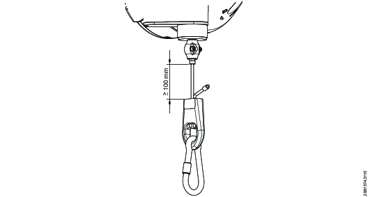
The minimum distance between the wire clamp and the wire wedge is 100 mm.
Remove the clamp from the wire wedge.
Adjust the wire length.
Make sure that the distance between the wire clamp and the wire wedge is no shorter than 100 mm.
Put the clamp back on the wire wedge.
Tighten the wire end with the supplied ferrule or a clamp in accordance with EN 13411-3:2022.
Cut the remaining wire end straight off.
Service
Maintenance Instructions
Servicing and inspection
Servicing and inspections must be done by an authorized workshop or a qualified service technician.
The instructions for use describe the installation and use of the balancer. Maintenance and repair may only be carried out by trained and qualified personnel. A trained and qualified person is any person who, on the basis of professional training, professional experience, activities carried out and training by the manufacturer or an authorised partner, has the necessary skills to carry out designated tasks independently.
Stop using the balancer if the following parts are damaged or significantly worn. Replace them before continuing to work.
Wire
Suspension
Safety chain
Snap hook
Signs of damage on the wire can be:
Broken stands
Cage type bulging
Flattened places or abrasion
Interval | Action |
|---|---|
Daily | Visually inspect:
|
Monthly | Visually inspect the equipment for damage and wear. Lubricate with non-corrosive grease:
|
Yearly | Visually inspect the equipment for damage and wear. |
Replacing the wire
It is possible to replace the wire without releasing the spring and without dismantling the balancer.
Fully retract the wire and make sure that the wire end is visible in the balancer housing slot.
Lock the wire drum.
Refer the below link to lock the wire drum correctly:
Remove the workload.
Pull out the wire end through the balancer housing slot by pushing the opposite wire end.
Remove the locking bush.
Pull out the wire through the balancer housing opening.
Push the replacement cable through the balancer housing opening and further out through the balancer housing slot.
Attach the locking bush.
Push the wire back into the housing.
Attach the workload.
Unlock the wire drum.
Replacement kits
The following information refer to our replacement kits.
Always follow the product instructions when replacing parts!