Tightening Editor
Buttons
Name | Description |
|---|---|
Display |
|
Zoom in | Zooms in on the tightening program. |
Zoom out | Zooms out from the tightening program. |
Fit to screen | Fits the whole tightening program to the drag and drop area. |
Delete | Deletes the selected item. |
Repair Area
The steps in the repair area show the repair path to be followed if the status at a synchronization point is NOK.
A repair path always starts and ends at a synchronization point. Where the repair path should re-enter the tightening path is flexible, but the repair path must always go back towards the beginning of the program.
Only one repair path can start in each synchronization point, but several repair paths may end at the same synchronization point.
The number of steps to run in the repair path can be between 1 and 3.
It is not possible to define a repair path from the start of the program.
Example: Repair paths
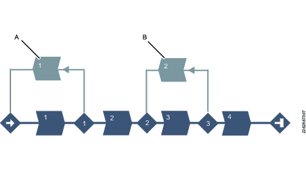
A | Repair path from the first synchronization point to the start of the program. |
B | Repair path from the third synchronization point to the second synchronization point. |
Tightening Area
The tightening area includes the tightening path, i.e., the steps and synchronization points in the multistep tightening program excluding repair and termination paths.
Number of Tightening Steps, Restrictions and Monitors Allowed
Number of Steps Allowed | Number of restrictions Allowed | Number of monitors Allowed | |
|---|---|---|---|
PF6000/PF8 | 16 | 8 | 8 |
PF6000/PF8 Step Sync | 25 (excluding syncpoints and repair- and termination paths) | 8 | 8 |
Flex | 25 (excluding syncpoints and repair- and termination paths) | 8 | 8 |
IxB | 16 | 5 | 8 |
Terminate Area
The steps in the terminate area shows the terminate path followed if the status at a synchronization point is fatal. After the termination path is done the tightening is ended. A termination path always starts at a synchronization point. Only one termination path can start in each synchronization point.
The number of steps to run in the termination path can be between one and three.
It is always possible to terminate from all synchronization points. If no termination path is defined, the program will go directly to the end without running any other steps.
Example: Termination path
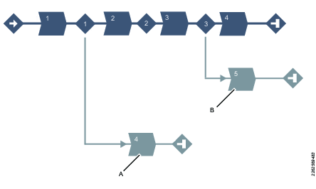
A | Termination path from the first synchronization point to the end of the program. |
B | Termination path from the third synchronization point to the end of the program. |
Configuration
Select on the step, restriction or monitor and click on Configuration at the bottom of the screen to open the Configuration field. To select multiple steps, use Ctrl.
The Configuration field contains different parameters for the steps, monitors and restrictions based on which step, monitor or restriction is selected in the repair area.
Enter the required parameters.
To delete a monitor or restriction, select Delete which is present in that field.
Using speed shifts
You can define 1-5 angle triggers or torque triggers during a step, where the speed will shift.
The speed shifts can be added in the Configuration field.
Within one step, all the speed shift triggers are based on the same property, i.e. either torque or angle. They cannot be mixed within one step.
To add a speed shift:
In the dialog box of a step that can have speed shifts, click Add speed shift and choose an angle range or a torque range. The Speed Shift Angle/Torque fields open.
Add values according to the table below.
Parameter | Description |
|---|---|
Angle/Torque trigger | Must be > 0. |
Speed | Must be > 0. |
Speed ramp type | Hard or soft. |
The Torque triggers and Angle triggers must be less than the step target, depending on the type of the step and the trigger type.
The Torque trigger and Torque speed also validate against the Max torque and Max speed of the tool. A warning or error indicator occurs whenever the Speed Shift settings exceed either the tool max values or step max values.
It is possible to push the settings to the controller when a tightening program has a warning, but not when a tightening program has an error(fault) indicator.
Tool Box
The Tool box includes:
Steps
Monitors
Restrictions
Drag and drop area shortcut keys
Shortcut key | Description |
|---|---|
Space bar + cursor | Move Drag and drop area. |
Drag and drop area functions
Function | Description | |
|---|---|---|
|
|
|
Add step |  | Grab a step in the Tool box. Drag the step to the desired position. Possible positions are indicated by a light blue indication arrow. |
___________ | __________________________ | _________________ |
Mark a step |  | Click on a step to mark it. |
___________ | __________________________ | _________________ |
Move a step | 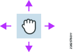 | To move a step, click on the step and hold the button pressed while moving. |
___________ | __________________________ | _________________ |
Copy step | 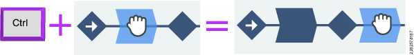 | To copy a step, click the Ctrl button and drag and drop the step. |
___________ | __________________________ | _________________ |
Add repair path | 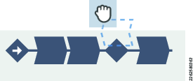 | Place the step above the synchronization point from where the repair part should start. |
___________ | __________________________ | _________________ |
Add repair step | 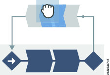 OR 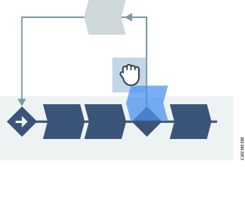 | Place a step in the Repair area to add a repair step. Possible positions are indicated by a light blue indication arrow. or Place the step above the synchronization point from where the repair part starts. The step is then placed before the first step in the repair path. |
___________ | __________________________ | _________________ |
Add terminate path | 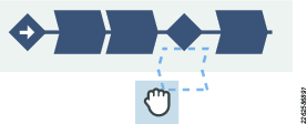 | Place the step below the synchronization point from where the termination part should start. |
___________ | __________________________ | _________________ |
Add terminate step | 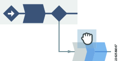 OR 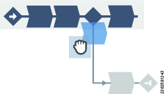 | Place a step in the Terminate area to add a terminate step. Possible positions are indicated by a light blue indication arrow. or Place the step below the synchronization point from where the termination part starts. The step is then placed before the first step in the termination path. |
___________ | __________________________ | _________________ |
Move endpoint for repair path. | 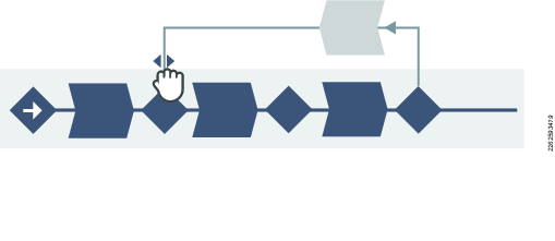 | Click the small arrow to move the endpoint of the repair path. |
___________ | __________________________ | _________________ |
Add restriction and monitor |  | Grab a restriction or a monitor in the Tool box. Drag the restriction or monitor to desired step. Possible steps to add a restriction or monitor to, are indicated by changing to a lighter blue color. |
___________ | __________________________ | _________________ |
Forbidden placement | 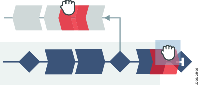 | A red arrow indicates that it is not possible to place a step. |
|
|


