Product Information
General Information
Warranty
Product warranty will expire 12 months after the product is first taken into use, but will in any case expire at the latest 13 months after delivery.
Normal wear and tear on parts is not included within the warranty.
Normal wear and tear is that which requires a part change or other adjustment/overhaul during standard tools maintenance typical for that period (expressed in time, operation hours or otherwise).
The product warranty relies on the correct use, maintenance, and repair of the tool and its component parts.
Damage to parts that occurs as a result of inadequate maintenance or performed by parties other than Atlas Copco or their Certified Service Partners during the warranty period is not covered by the warranty.
To avoid damage or destruction of tool parts, service the tool according to the recommended maintenance schedules and follow the correct instructions.
Warranty repairs are only performed in Atlas Copco workshops or by Certified Service Partners.
Atlas Copco offers extended warranty and state of the art preventive maintenance through its ToolCover contracts. For further information contact your local Service representative.
For electrical motors:
Warranty will only apply when the electric motor has not been opened.
ServAid
ServAid is a portal that is continuously updated and contains Technical Information, such as:
Regulatory and Safety Information
Technical Data
Installation, Operation and Service Instructions
Spare Parts Lists
Accessories
Dimensional Drawings
Please visit: https://servaid.atlascopco.com.
For further Technical Information, please contact your local Atlas Copco representative.
Safety Data Sheets MSDS/SDS
The Safety Data Sheets describe the chemical products sold by Atlas Copco.
Please consult the Atlas Copco website for more information www.atlascopco.com/sds.
Country of Origin
For the Country of Origin, please refer to the information on the product label.
Dimensional Drawings
Dimensional Drawings can be found either in the Dimensional Drawings Archive, or on ServAid.
Please visit: http://webbox.atlascopco.com/webbox/dimdrw or https://servaid.atlascopco.com.
Overview
Atlas Copco Air Driven Pump Unit
Atlas Copco air driven pump units operate on the simple but efficient principle of power magnification through the use of differential areas. A relatively large air-operated piston drives the smaller piston, which provides fluid flow at high pressures. All Atlas Copco air driven pump units are fitted into an easily transportable, tubular steel frame.
The pump units are available, fitted with a large choice of pressure gauges and are supplied complete with an air pressure regulator which can be set to stall the pump unit when it reaches the pressure required for each particular tensioning application.
Introduction
The operating and maintenance procedures listed within this manual should be adhered to and will enable the operator to obtain maximum efficiency and reliability from the equipment.
Precautions
Prior to connecting the hydraulic pump to any equipment, the user is to ensure that :
The working pressure of the hydraulic pump and the equipment to be operated are compatible. i.e. maximum working pressure of the hydraulic tensioning tools, hydraulic connections & hydraulic hoses.
The reservoir pump capacity is adequate to operate the equipment throughout its range.
The hydraulic oil specification used within the pump and the equipment are compatible.
Technical Product Data
Technical Product Data can be found on either ServAid, or the Atlas Copco website.
Please visit: https://servaid.atlascopco.com or www.atlascopco.com.
Service Overview
Service Recommendations
Preventive maintenance is recommended at regular intervals. See the detailed information on preventive maintenance. If the product is not working properly, take it out of service and inspect it.
If no detailed information about preventive maintenance is included, follow these general guidelines:
Clean appropriate parts accurately
Replace any defective or worn parts
Installation
Installation Instructions
Before Connecting the Air Supply
It is strongly recommended that the pump is regulated in order to stall at the required tensioning pressure. This is achieved by adjustment of the air regulator valve.
Before connecting an air supply, it is important to check the following,
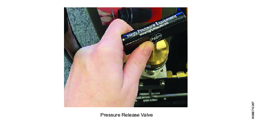
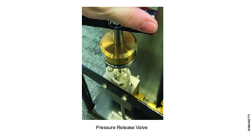
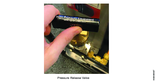
The pressure release valve is fully open (rotated fully anti-clockwise).
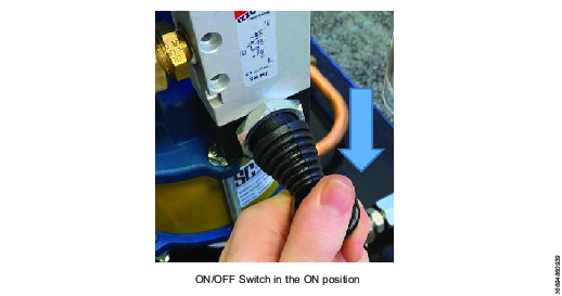
The On /Off valve is off (In the horizontal position). The On/OFF valve is by default closed until manually operated and held.
The oil Tank has sufficient oil (Grade ISO 10, 32, 68).
Check that the cap seal plug has been removed.

The oil tank on this pump unit is fitted with a cap seal plug to prevent oil spillage during transit. Remove the M6 cap screw and seal from tank cap prior to use.The oil tank on this pump unit is fitted with a cap seal plug to prevent oil spillage during transit. Remove the M6 cap screw and seal from tank cap prior to use.
In the event of the pump being used at sub-zero temperatures, add deicer additives to the oil to prevent the oil from freezing.
Setting pump stall pressure
Atlas Copco supply all pump units with the air pressure regulator set to stall the pump at its maximum working pressure. Connect the main air supply to the pump unit. Slowly activate the safety On/Off valve by holding the control down, the pump will begin to operate, no pressure can be generated because the pressure release valve is open, so the oil is simply circulated through the system back to the tank.
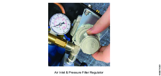
Before adjusting the pressure on the air filter/regulator, it is necessary for the ‘Snap Action Lock’ to be in the up position. By turning the adjustment knob anticlockwise on the regulator, reduce the air pressure to zero PSI, the pump will slow down considerably and may even stop.
Fully close the pressure release valve by rotating clockwise to stop. As this is done, a slight pressure will be generated on the pressure gauge and the pump will finally stall.
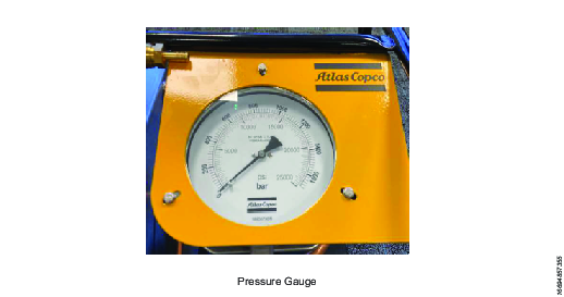
Slowly increase the air supply pressure by turning the adjustment knob clockwise, the oil pressure gauge will indicate a higher pressure as more and more air is allowed into the pump unit. Stop the air adjustment when the oil pressure gauge indicates the desired tensioning pressure.
Stop the pump by releasing the On/Off valve and release the pressure by slowly opening the pressure return valve, the pump gauge will fall to zero. Lock the air regulator by pushing down on to the ‘Snap Action Lock’.
Operate the pump again and allow it to stall, check the pressure and further adjust if necessary. When satisfied that the pump stall pressure is correct the pump unit is now ready for the tensioning operation.
Pump Preparation
Ensure the pressure release valve is in the open position (rotate anti-clockwise to stop). The pressure relief valve is fitted with a torque limiter to prevent over tightening it. Limiter will ‘Click Out’ as a preventative measure.

Ensure the On/Off valve is in the off position.
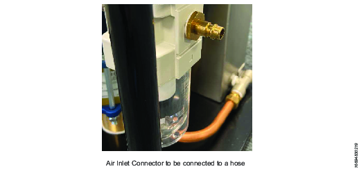
Connect the air hose to the air inlet connector. Give the hose a sharp tug afterwards, to ensure a solid connection.
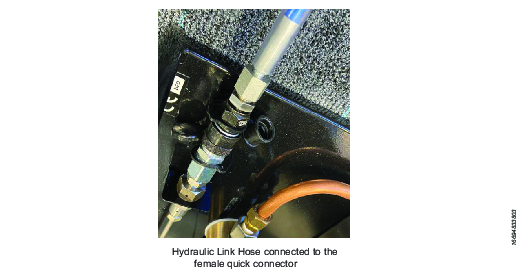
Connect the hydraulic link hose to the female quick connector. (Refer to the operation manual supplied with your tensioners for correct hydraulic link hose configuration)
Ensure an adequate volume of oil is contained in the Oil Tank.
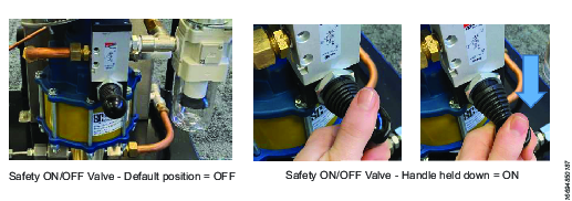
Safety On/Off Valve
The pump unit is fitted with a safety On/Off valve. The spring loaded valve defaults to off when the valve handle is untouched. Holding the valve handle in the down position turns the pump on. Releasing the handle turns the pump off.
Operation
Ergonomic Guidelines
Consider your workstation as you read through this list of general ergonomic guidelines to identify areas for improvement in posture, component placement, or work environment.
Take frequent breaks and change work positions frequently.
Adapt the workstation area to your needs and the work task.
Adjust for a convenient reach range by determining where parts and tools need to be located to avoid static load.
Use workstation equipment such as tables and chairs appropriate for the work task.
Avoid work positions above shoulder level or with static holding during assembly operations.
When working above shoulder level, reduce the load on the static muscles by lowering the weight of the tool, using for example torque arms, hose reels or weight balancers. You can also reduce the load on the static muscles by holding the tool close to the body.
Take frequent breaks.
Avoid extreme arm or wrist postures, particularly during operations requiring a degree of force.
Adjust for a convenient field of vision that requires minimal eye and head movements.
Use appropriate lighting for the work task.
Select the appropriate tool for the work task.
In noisy environments, use ear protection equipment.
Use high-quality inserted tools and consumables to minimize exposure to excessive levels of vibration.
Minimize exposure to reaction forces.
When cutting:
A cut-off wheel can get stuck if the cut-off wheel is bent or not guided properly. Use the correct flange for the cut-off wheel and avoid bending the cut-off wheel during operation.
When drilling:
The drill might stall when the drill bit breaks through. Use support handles if the stall torque is high. The safety standard ISO11148 part 3 recommends using a device to absorb a reaction torque above 10 Nm for pistol grip tools and 4 Nm for straight tools.
When using direct-driven screwdrivers or nutrunners:
Reaction forces depend on the tool settings and joint characteristics. Strength and posture determine the amount of reaction force that an operator can tolerate. Adapt the torque setting to the operator's strength and posture and use a torque arm or reaction bar if the torque is too high.
In dusty environments, use a dust extraction system or wear a mouth protection mask.
Ergonomic Guidelines
Consider your workstation as you read through this list of general ergonomic guidelines to identify areas for improvement in posture, component placement, or work environment.
Take frequent breaks and change work positions frequently.
Adapt the workstation area to your needs and the work task.
Adjust for a convenient reach range by determining where parts and tools need to be located to avoid static load.
Use workstation equipment such as tables and chairs appropriate for the work task.
Avoid work positions above shoulder level or with static holding during assembly operations.
When working above shoulder level, reduce the load on the static muscles by lowering the weight of the tool, using for example torque arms, hose reels or weight balancers. You can also reduce the load on the static muscles by holding the tool close to the body.
Take frequent breaks.
Avoid extreme arm or wrist postures, particularly during operations requiring a degree of force.
Adjust for a convenient field of vision that requires minimal eye and head movements.
Use appropriate lighting for the work task.
Select the appropriate tool for the work task.
In noisy environments, use ear protection equipment.
Use high-quality inserted tools and consumables to minimize exposure to excessive levels of vibration.
Pump Operation
Close the pressure release valve (clockwise).
Hold down the On/Off valve. The pressure gauge will slowly indicate pressure.
Once the desired pressure is reached, release the On/Off valve. The valve will spring back to the Off position. Check the pressure reading on the oil pressure gauge. (Ensure the pressure is holding steady before approaching any pressurised bolt tensioning equipment).

To release the hydraulic pressure slowly open the pressure release valve (anticlockwise), the pressure will slowly fall.
Shut down procedure
Disconnect the main air supply.
Open the oil pressure release valve.
Open the On/Off valve (air will vent through the exhaust).
Close the On/Off valve
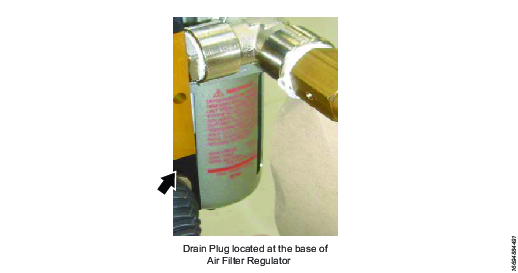
Drain water from the air filter
Top-up the oil tank
Store in pump box supplied.
Adjustment of Pressure Release Valve (PRV)
The PRV is factory set to vent air should the pump over pressurise. Adjustment is not necessary.
Operating Instructions
Shut down procedure
Disconnect the main air supply.
Open the oil pressure release valve.
Open the On/Off valve (air will vent through the exhaust).
Close the On/Off valve
Drain water from the air filter
Top-up the oil tank
Store in pump box supplied.
Adjustment of Pressure Release Valve (PRV)
The PRV is factory set to vent air should the pump over pressurise. Adjustment is not necessary.
Service
Maintenance Instructions
Service Recommendations
Preventive maintenance is recommended at regular intervals. See the detailed information on preventive maintenance. If the product is not working properly, take it out of service and inspect it.
If no detailed information about preventive maintenance is included, follow these general guidelines:
Clean appropriate parts accurately
Replace any defective or worn parts
Lubrication Instructions
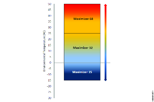
Hydraulic Fluid
The performance of hydraulic equipment is heavily dependent on the quality and characteristics of the hydraulic fluid selected for use. The choice of the specification and viscosity of the hydraulic fluid should be based of the conditions of use, taking into account several factors as follows:
The range of environmental temperature.
The range of oil viscosity defined for the equipment.
The application (range of pressures, sources of contamination of the hydraulic fluid, the type of pump, etc.)
The ease of getting a proper replacement or equivalent hydraulic fluid.
Example: ISO Grade 15, 32 and 68.
For changing or refilling the oil, it is recommended to use the same oil as supplied with the pump.
Hydraulic Oil Selection Chart
Please use the link below to find our safe data sheets for Maximizer.
https://www.atlascopco.com/en-uk/sys/safetydatasheets
Troubleshooting
Troubleshooting
If for any reason the pump does not run properly, look for one of the following causes,
If the pump appears to be short stroking and running too fast without pumping properly, it usually indicates that the pilot valve assembly is not working as it should be. (See also Hydraulic Pump Seal Replacement refer "The hydraulic piston" and "Repairing the pilot valve assembly" for correction procedure).
Loss of pressure may be caused by one of two reasons, the hydraulic check valves have developed a leak or the hydraulic fluid is bleeding past the packing in the hydraulic Cylinder. (See also Hydraulic Pump Seal Replacement to replace the packing in the hydraulic cylinder", "The hydraulic piston" and "Repairing or replacing the hydraulic check valves for the correction procedure).
Should the pump run erratically and in a jerky manner after a period of time, it is usually an indication of seizing in the hydraulic piston & cylinder assembly. (See also Hydraulic Pump Seal Replacement refer "To disassemble the air motor" and "To replace the packing in the hydraulic cylinder for disassembly instructions). If the hydraulic piston and cylinder have not been damaged, a thorough cleaning will normally place the pump in operation again.
To ensure hydraulic fluid flow is optimised, ensure sufficient air volume is supplied to the pump. Hooking the pump up to a smaller pipe size than the “AIR IN” port on the pump will not allow it to run at its full rated capacity. Long runs of relatively small pipe supplying air to the pump will have the same effect.
If an excessive amount of oil or water is pouring through the pump air exhaust, check for and correct;
Lubricating unit in the air supply is delivering too much oil. Adjust to about one drop of oil for every 20 strokes of the pump.
The hydraulic fluid being pumped (oil or water) may be leaking past the packing in the hydraulic cylinder into the air motor. (See also Hydraulic Pump Seal Replacement refer "To replace the packing in the hydraulic cylinder" for correction procedure).
Recycling
Environmental Regulations
When a product has served its purpose it has to be recycled properly. Dismantle the product and recycle the components in accordance with local legislation.